1
OPERATOR'S MANUAL
CLEAN BURN MODELS: CB-1500 and CB-2500 MULTI-OIL FURNACES
with CB-500 Series Burner
230 V / 50 Hz
2 20
-2 40
5 0-
W
z3
60H t s 10s
foss
Dan
64
BHO 036
pe
Ty 05 7H7
Nr.
FOR YOUR SAFETY DO NOT STORE GASOLINE
OR OTHER FLAMMABLE VAPORS AND LIQUIDS
IN THE VICINITY OF THIS OR ANY APPLIANCE!!
PUBLICATION DATE: 6/1/10, Rev. 4
I88942
CLEAN BURN PART # 43161
WARNING: DO NOT assemble, install, operate, or maintain this equipment without first
reading and understanding the information provided in this manual. Installation and
service must be accomplished by qualified personnel. Failure to follow all safety precautions
and procedures as stated in this manual may result in property damage, serious personal injury
or death.
CLEAN BURN, INC. • 34 Zimmerman Road • Leola, PA 17540 • U.S.A.
The Clean Burn logo is a trademark of Clean Burn, Inc. All other brand or product names mentioned are the registered
trademarks or trademarks of their respective owners.
Copyright © 2009 Clean Burn, Inc. All rights reserved. No part of this publication may be reproduced, or distributed without
the prior written permission of Clean Burn, Inc. 34 Zimmerman Road, Leola, PA 17540. Subject to change without notice.
DECLARATION OF CONFORMITY
Manufacturer:
Clean Burn Inc .
34 Zimmerman Rd.
Leola, PA
USA
European Re presentative:
Please call 1-800-331-0183 for
authorized European distributors
Equipment:
CB-1500 CE # 90191
CB-2500 CE # 90158
EMC Competent Body:
TÜV Rheinland Product Safety GmbH
Am Grauenstein,
D-51105 Köln
I hereby declare that the above named machinery complies with Essential Health and Safe ty
Requirements of the Industrial Machinery Directive (IM D - 98/37/EEC) as amended, with the
Low Voltage Directive (LVD – 73/23/EEC) as amended, and with the Electroma gnetic
Compatibility Directive (EMC – 89/336/EEC) as amended.
Safety Standard:
EN 230: 1990
EN 292-1:1991
EN 292-2:1991+A1
EN 60204-1:2000
EMC Standards:
EN 55014-1: 2000
EN 55014-2: 2000
EN 50165: 1997
M onobloc Oil Burners – Safety, Control, and Regulation Device s and
Safety Times.
Safety of machinery - Basic concepts, general principles for design - Pa rt
1 : Basic terminology, methodology.
Safety of machinery - Basic concepts, general principles for design - Pa rt
2 : Technical principles a nd specifications
Safety of machinery. Electrical equipment of machines. General
requirements.
Electromagnetic Compatibility – Requirements for Household Appliances,
Electric Tools, and Similar Appa ratus. Part 1: Emission.
Electromagnetic Compatibility – Requirements for Household Appliances,
Electric Tools, and Similar Appa ratus. Part 2: Immunity.
Electrical Equipment of Non-Elec tric Appliances for Household and
Similar Purposes. Safety Requirements.
Note: Above equipment is subject to an EMC Tec hnical Construction File and Competent Body
Certificate Number AV 72031804 0001.
11 Fe br ua ry, 2009
Rya n D. Ga mbe r
Enginee ring M anager
TABLE OF CONTENTS
SECTION 1: INTRODUCTION .................................................................................... 1-1
Guide to this Manual ........................................................................................................ 1-1
For Your Safety... ............................................................................................................. 1-2
Guidelines for Furnace Usage ................................................................................... 1-4
Guidelines for Used Oil Tanks .................................................................................. 1-5
Safety Labels ............................................................................................................. 1-6
SECTION 2: UNPACKING ......................................................................................... 2-1
Removing the Shipping Crate .......................................................................................... 2-1
Unpacking and Inspecting All Components..................................................................... 2-1
Furnace Component List ........................................................................................... 2-1
Unpacking Items Packed Inside the Furnace ............................................................. 2-2
SECTION 3: FURNACE ASSEMBLY ......................................................................... 3-1
Understanding Assembly ................................................................................................. 3-1
Required Tools and Materials ...................................................................................... 3-1
Overview of Furnace Assembly .......................................................................................... 3-2
Installing the Blower Assembly ..................................................................................... 3-3
Wiring the Blower Motor ............................................................................................. 3-4
Determining the Hot Air Discharge Configuration ................................................................ 3-5
Installing the Hot Air Discharge Components ...................................................................... 3-6
Installing the Energy Retention Disc ..................................................................................... 3-9
Installing the Energy Retention Disc in the Combustion Chamber ................................... 3-9
Closing the Furnace Door ............................................................................................ 3-9
Installing the Burner ............................................................................................................ 3-9
Checking the Burner Nozzle and Electrodes ................................................................. 3-9
Mounting the Burner on the Hinge Bracket ................................................................. 3-11
Installing the Connector Block, Oil Line Tubing, and Air Line Tubing ................................. 3-12
Installing the Connector Block on the Furnace Door ................................................... 3-12
Installing the Oil Line Tubing ...................................................................................... 3-12
Installing the Air Line Tubing ...................................................................................... 3-13
Locking the Burner into Firing Position ....................................................................... 3-14
SECTION 4: FURNACE INSTALLATION ................................................................... 4-1
Understanding Installation ............................................................................................... 4-1
Important Safety Guidelines for Safe Installation ..................................................... 4-1
Selecting a Location ......................................................................................................... 4-5
Guidelines for Selecting a Location .......................................................................... 4-5
Mounting the Furnace ...................................................................................................... 4-6
Ceiling Mounting ...................................................................................................... 4-6
Raised Platform Mounting ........................................................................................ 4-7
Floor Mounting.......................................................................................................... 4-7
TABLE OF CONTENTS
SECTION 4: FURNACE INSTALLATION (continued)
Oil Tank Installation Specifications ................................................................................. 4-8
Installing the Tank Vent and Emergency Vent .......................................................... 4-9
Installing the Metering Pump ......................................................................................... 4-10
Preparing for Installation ......................................................................................... 4-10
Standard Mounting: Vertical Positioning ................................................................ 4-10
Alternate Mounting: Horizontal Positioning ........................................................... 4-12
Wiring the Furnace and Pump ........................................................................................ 4-13
Wiring to the Furnace .............................................................................................. 4-13
Wiring to the Metering Pump ..................................................................................... 4-13
Installing the Suction Oil Line Components ........................................................................ 4-14
Installing the Pressure Relief Oil Line Back to the Tank ..................................................... 4-17
Installing the Pressure Oil Line Components ...................................................................... 4-18
Installing the Compressed Air Line .................................................................................... 4-18
Installing the Stack ........................................................................................................... 4-19
Stack Design and Specifications ................................................................................. 4-19
Installing the Interior Stack ......................................................................................... 4-22
Installing the Barometric Damper ............................................................................... 4-22
Installing the Stack Penetration ................................................................................... 4-23
Installing the Exterior Stack ........................................................................................ 4-23
Installing the Stack Cap ............................................................................................. 4-23
Installing the Optional Draft Inducer ........................................................................... 4-23
Installing the Wall Thermostat ........................................................................................... 4-25
Inspecting the Furnace Installation ..................................................................................... 4-25
SECTION 5: METERING PUMP PRIMING ................................................................ 5-1
Understanding Metering Pump Priming .......................................................................... 5-1
Required Tools and Materials ...................................................................................... 5-1
Priming the Metering Pump ................................................................................................. 5-2
Vacuum Testing the Oil Pump ............................................................................................. 5-4
SECTION 6: STARTING AND ADJUSTING THE BURNER ...................................... 6-1
Understanding Burner Startup and Adjustment ............................................................... 6-1
Preparing the Burner for Startup ...................................................................................... 6-1
Starting the Burner ........................................................................................................... 6-3
Checking the Operation of the Blower Motor ..................................................................... 6-4
SECTION 7: RESETTING THE FURNACE AND BURNER ....................................... 7-1
Understanding Furnace/Burner Shutdowns ..................................................................... 7-1
The Oil Primary Control .................................................................................................. 7-1
Resetting the Oil Primary Control ............................................................................. 7-1
The Blower/Fan Switch .................................................................................................... 7-2
The Hi-Temp Limit Switches ........................................................................................... 7-2
Understanding the L-200 Hi-Temp Limit Switch ..................................................... 7-2
Understanding the L-290 Auxiliary Hi-Temp Limit Switch ............................................ 7-2
TABLE OF CONTENTS
SECTION 8: ADJUSTING THE DRAFT OVER FIRE ................................................ 8-1
Checking for Correct Draft Over Fire ................................................................................. 8-1
Adjusting the Barometric Damper ....................................................................................... 8-2
Solving Draft Overfire Problems ......................................................................................... 8-2
Understanding the Effect of Exhaust Fans on Draft ....................................................... 8-3
Checking Draft Overfire to Determine Severity of Backdraft ......................................... 8-3
Installing a Make-up Air Louver .................................................................................. 8-5
SECTION 9: MAINTENANCE ..................................................................................... 9-1
Understanding Maintenance ................................................................................................ 9-1
Periodic Burner Inspection ................................................................................................. 9-2
Cleaning the Canister Filter ................................................................................................. 9-3
Servicing the Metering Pump .............................................................................................. 9-4
Cleaning Ash from the Furnace ........................................................................................... 9-5
Cleaning the Check Valve / Screen ..................................................................................... 9-7
Cleaning the Tank .............................................................................................................. 9-8
Annual Burner Tune-up ...................................................................................................... 9-8
End of Season Maintenance ............................................................................................... 9-8
SECTION 10: TROUBLESHOOTING ....................................................................... 10-1
Troubleshooting Flow Chart .......................................................................................... 10-2
Troubleshooting Tables .................................................................................................. 10-3
APPENDIX A
Detailed Furnace Specifications ...................................................................................... A-1
Furnace Technical Specifications ............................................................................. A-1
Burner Technical Specifications ............................................................................... A-2
Furnace Dimensions ................................................................................................. A-3
Burner Components ................................................................................................... A-4
Removing the Nozzle for Cleaning ......................................................................... A-9
Furnace Components ............................................................................................... A-10
CB-1500 Furnace Components .......................................................................... A-10
CB-2500 Furnace Components .......................................................................... A-12
Blower Components ................................................................................................. A-14
CB-1500 Blower Components ........................................................................... A-14
CB-2500 Blower Components ........................................................................... A-16
APPENDIX B
Wiring Diagrams ............................................................................................................... B-1
Furnace Wiring Diagram ............................................................................................. B-1
Burner Wiring Diagram ............................................................................................... B-2
Ladder Schematic ...................................................................................................... B-3
Metering Pump Wiring Schematics .............................................................................. B-4
TABLE OF CONTENTS
APPENDIX C
Additional Installation and Maintenance Requirements ................................................. C-1
Installing a Cover over the Oil/Air Regulators ......................................................... C-1
Installing a Fire Valve .............................................................................................. C-2
APPENDIX D
Furnace Service Record .................................................................................................... D-1
Operator's Manual: Models CB-1500 & CB-2500 (230 V / 50 Hz)
SECTION 1: INTRODUCTION
Guide to this Manual
This manual contains all the information necessary to safely install and operate the Clean Burn
CE-certified, 230 V / 50 Hz Furnace Models CB-1500 and CB-2500. Consult the Table of Contents for a
detailed list of topics covered. You'll find this manual's step-by-step procedures easy to follow and understand.
Should questions arise, please contact your Clean Burn dealer before starting any of the procedures in this
manual.
As you follow the directions in this manual, you'll discover that assembling and operating your new
furnace involves five basic activities as outlined here:
•
•
•
•
•
UNPACKING ....................................................................................................
ASSEMBLY ......................................................................................................
INSTALLATION .............................................................................................
OPERATION
• Metering Pump Priming ......................................................................
• Starting and Adjusting the Burner .....................................................
• Resetting the Furnace and Burner ......................................................
• Adjusting the Draft ...............................................................................
MAINTENANCE .............................................................................................
The manual also contains important and detailed technical
reference materials which are located at the back of the
manual in the Appendixes.
(Section 2)
(Section 3)
(Section 4)
(Section 5)
(Section 6)
(Section 7)
(Section 8)
(Section 9)
WARNING!
Please read all sections carefully--including the important
safety information found in this section--before beginning
any installation/operation procedures; doing so ensures
your safety and the optimal performance of your Clean
Burn furnace.
STOP
YOUR SAFETY IS AT STAKE!
DO NOT INSTALL, OPERATE OR
MAINTAIN THIS EQUIPMENT
WITHOUT FIRST READING
AND UNDERSTANDING THE
OPERATOR'S MANUAL!
1-1
Operator's Manual: Models CB-1500 & CB-2500 (230 V / 50 Hz)
For Your Safety...
For your safety, Clean Burn documentation contains the following types of safety statements (listed here
in order of increasing intensity):
•
NOTE: A clarification of previous information or additional pertinent information.
•
ATTENTION: A safety statement indicating that potential equipment damage may occur if
instructions are not followed.
CAUTION: A safety statement that reminds of safety practices or directs attention to unsafe
practices which could result in personal injury if proper precautions are not taken.
WARNING: A strong safetystatement indicating that a hazard exists which can result in
injury or death if proper precautions are not taken.
DANGER! The utmost levels of safety must be observed; an extreme hazard exists which
would result in high probability of death or irreparable serious personal injury if proper
precautions are not taken.
In addition to observing the specific precautions listed throughout the manual, the following general
precautions apply and must be heeded to ensure proper, safe furnace operation.
DANGER! DO NOT create a fire or explosion hazard by storing or using gasoline or other
flammable or explosive liquids or vapors near your furnace.
DANGER! DO NOT operate your furnace if excess oil, oil vapor or fumes have
accumulated in or near your furnace. As with any oil burning furnace, improper installation,
operation or maintenance may result in a fire or explosion hazard.
WARNING: DO NOT add inappropriate or hazardous materials to your used oil, such as:
• Anti-freeze
• Carburetor cleaner
• Paint thinner
• Parts washer solvents
• Gasoline
• Oil additives
• Any other inappropriate/hazardous
material
WARNING: Burning chlorinated materials (chlorinated solvents and oils) is illegal, will
severely damage your heat exchanger, and adversely affect the proper, safe operation of your
furnace. Instruct your personnel to never add hazardous materials to your used oil.
1-2
Operator's Manual: Models CB-1500 & CB-2500 (230 V / 50 Hz)
For Your Safety... (continued)
WARNING: Never alter or modify your furnace without prior written consent of
Clean Burn, Inc. Unauthorized modifications or alteration can adversely affect the proper,
safe operation of your furnace.
WARNING: The burner which is shipped with your Clean Burn furnace is to be used only
with your furnace according to the instructions provided in this manual. DO NOT use the
burner for any other purpose!
WARNING: Electrical installation of the furnace is to be performed only by qualified
personnel (i.e. licensed electrician/engineer). Improper electrical installation can adversely
affect the proper, safe operation of the furnace and may cause serious personal injury/death.
WARNING: Install the furnace in an area away from the main shop traffic. (Clean Burn
recommends ceiling mounting for this purpose.) It is essential for personal safety that only
manufacturer-trained, qualified personnel have access to operate and maintain the
furnace.
WARNING: To prevent damage to the furnace and to ensure personal safety, lifting,
mounting, and hanging of the furnace must be performed in accordance with safe handling
procedures.
WARNING: DO NOT operate your furnace when the ambient temperature is above
35o C (95o F).
WARNING: The Best Operator is a Careful Operator! By using common sense,
observing general safety rules, and adhering to the precautions specific to the equipment, you,
the operator, can promote safe equipment operation. Failure to use common sense, observe
general safety rules, and adhere to the precautions specific to the equipment may result in
equipment damage, fire, explosion, personal injury and/or death.
WARNING: The installation, operation, and maintenance of this equipment must be
accomplished by qualified personnel and in compliance with the specifications in the
Clean Burn Operator's Manual and with all national, state, and local codes or authorities
having jurisdiction over environmental control, building inspection and fuel, fire and
electrical safety.
WARNING: This equipment is for commercial and/or industrial use only; it is NOT for
residential use.
WARNING: Call your Clean Burn dealer for service. DO NOT allow untrained, unauthorized
personnel to service your furnace. Make sure that your furnace receives periodic maintenance to
ensure optimal performance
Failure to comply with these standards and requirements may result in equipment dam
age, fire, explosion, personal injury and/or death.
1-3
Operator's Manual: Models CB-1500 & CB-2500 (230 V / 50 Hz)
For Your Safety... (continued)
Guidelines for Furnace Usage
•
This furnace is listed for commercial and/or industrial use only; it is not listed for residential
use.
•
This furnace is designed to burn the following fuels:
• Used crankcase oil up to 50 SAE
• Used transmission fluid
• Used hydraulic oils
• #2 fuel oil
• #4 fuel oil
• #5 fuel oil
NOTE: Used oils may contain other substances, including gasoline, that may hinder
performance.
•
Make sure you comply with all environmental regulations concerning the use of your furnace.
These regulations require that:
• Your used oil is generated on-site. You may also accept used oil from
"do-it-yourself" oil changers.
• Hazardous wastes, such as chlorinated solvents, are NOT to be mixed with your
used oil.
• The flue gases are vented to the outdoors with an appropriate stack.
• Your used oil is recycled as fuel for "heat recovery". DO NOT operate your furnace
in warm weather just to burn oil.
Contact your local Clean Burn dealer for current environmental regulations.
•
If your furnace ever requires service, call your Clean Burn dealer. DO NOT allow
untrained, unauthorized personnel to service your furnace. Make sure that your furnace
receives annual preventative maintenance to ensure optimal performance.
1-4
Operator's Manual: Models CB-1500 & CB-2500 (230 V / 50 Hz)
For Your Safety... (continued)
Guidelines for Used Oil Tanks
For the safe storage of used oil and the safety of
persons in the vicinity of the used oil supply tank,
ensure that your tank installation adheres to the
following safety guidelines:
•
•
•
•
The tank installation must meet all
national and local codes. Consult your
local municipal authorities for more
information as necessary.
Review and adhere to the safety
guidelines for used oil supply tanks
as stated in the WARNING shown.
Ensure that the tank for your furnace
installation complies with all code and
safety requirements as stated here. If the
tank does not comply, DO NOT use it.
If you do not have a copy of the tank
safety label pictured at right, please
contact your Clean Burn dealer for the
label, which is to be affixed directly on
your used oil supply tank.
1-5
Operator's Manual: Models CB-1500 & CB-2500 (230 V / 50 Hz)
For Your Safety... (continued)
Safety Labels
Following are the locations and descriptions of all labels on your CB-1500 or CB-2500 furnace. The following
illustrations show the location of ALL labels on your furnace. Please note that some labels denote model
number, model description, etc. while others contain important safety messages.
Each Safety Label contains an important safety message starting with a key word as discussed earlier in
this section (e.g. ATTENTION, CAUTION, WARNING, DANGER). For your safety and the safe
operation of your furnace, review all labels and heed all safety messages as printed on the labels.
If any labels on your Clean Burn furnace ever become worn, lost or painted over, please call your Clean
Burn dealer for free replacements.
42308
Danfoss
42363
42439
42457
220−240V 50−60Hz 3W
ts 10s
Type BHO 64
Nr. 057H7036
42367
I88888
Label Part #
42030
42027
42308
42363
42439
42341
42457
42333
42368
42367
42315
42068
Description
Furnace Electrical Shock Hazard Warning Label (several locations)
Furnace Burn Hazard/Hazardous Voltage Warning Label
Header Label
CE Data Label - CB-2500
CE Data Label - CB-1500
Cleaning Combustion Chamber/Target Caution Label
Made in USA / Pat Pending Combination Label
Model CB-2500 Label
Model CB-1500 Label
Furnace Safety Warning Label (Multiple Messages - Fire/Shock/Burn Hazards)
Burn Hazard - Hot Surface Warning Label
Furnace Blower/Fan Entanglement Hazard Warning Label (near blower)
1-6
Operator's Manual: Models CB-1500 & CB-2500 (230 V / 50 Hz)
For Your Safety... (continued)
CB-1500/CB-2500 Furnace Cabinet Safety Labels
1-7
Operator's Manual: Models CB-1500 & CB-2500 (230 V / 50 Hz)
For Your Safety... (continued)
CB-1500/CB-2500 Furnace Cabinet Safety Labels
CLEAN BURN, INC.
CLEAN BURN, INC.
LEOLA, PENNSYLVANIA (USA)
LEOLA, PENNSYLVANIA (USA)
CB 1500
CB 2500
BTU/HR
(KW)
250,000
73
1.1
BTU/HR
(KW)
150,000
44
3.9
14.0
1.0
1.3
0.1
1.7
6.4
18.0
1.2
3.5
0.24
1.1
4.0
14.0
1.0
2.0
0.1
1.7
6.4
16.0
1.1
4.0
0.28
1.1
4.0
14.0
1.0
2.0
0.1
1.7
6.4
17.0
1.2
4.0
0.28
1.1
4.0
16.0
1.1
2.0
0.1
1.7
6.4
17.0
1.2
4.0
0.28
−.04 (−1 mm)
−.04 (−1 mm)
TOP
TOP
12 (30)
60 (152)
18 (46)
BLOWER
2 (5)
18 (46)
DISCHARGE
60 (152)
12 (30)
18 (46)
18 (46)
60 (152)
2 (5)
60 (152)
24 (61)
CLOSED
BLOWER
W/LOUVERS
DISCHARGE
38 (97)
24 (61)
POWER
HZ
50
POWER
5.0
3/4
230
230
0.4
50
1/17
230
0.45
50
1/10
450
230
1.7
50
1/50
230
0.5
1/3
230
1.8
1
230
1/17
1/10
4.0
HZ
50
230
0.4
50
230
0.45
50
450
230
1.7
50
50
1/50
230
0.5
50
50
1/3
230
1.8
50
10
9
15
15
THE MAINTENANCE INTERVAL FOR CLEANING ASH FROM THE FURNACE IS
APPROXIMATELY 700 HOURS. THE ASH LEFT FROM THE BURNING OF USED OIL
MAY CONTAIN METALLIC COMPOUNDS OR FOREIGN MATERIALS. THE ASH MUST BE
DISPOSED OF PROPERLY.
THE MAINTENANCE INTERVAL FOR CLEANING ASH FROM THE FURNACE IS
APPROXIMATELY 700 HOURS. THE ASH LEFT FROM THE BURNING OF USED OIL
MAY CONTAIN METALLIC COMPOUNDS OR FOREIGN MATERIALS. THE ASH MUST BE
DISPOSED OF PROPERLY.
BURNER REQUIRES A MINIMUM AIR SOURCE OF:
2 S.C.F.M. (57 L/MIN.) AT 25 P.S.I. (1.72 BAR).
THIS APPLIANCE IS NOT TO BE USED WITH AIR FILTERS AND
SHALL INCORPORATE NO PROVISIONS FOR MOUNTING AIR FILTERS.
BURNER REQUIRES A MINIMUM AIR SOURCE OF:
2 S.C.F.M. (57 L/MIN.) AT 25 P.S.I. (1.72 BAR).
THIS APPLIANCE IS NOT TO BE USED WITH AIR FILTERS AND
SHALL INCORPORATE NO PROVISIONS FOR MOUNTING AIR FILTERS.
42363
42439
NO.
MULTI−OIL HEATING SYSTEM
FOR COMMERCIAL OR INDUSTRIAL USE ONLY.
42308
1-8
Operator's Manual: Models CB-1500 & CB-2500 (230 V / 50 Hz)
For Your Safety... (continued)
CB-1500/CB-2500 Burner Labels
Label Part #
Description
42004
42235
42339
42229
42482
42309
42023
42457
Burner Safety Warning Label (High Voltage/Moving Parts Hazards)
Burner Safety Warning Label (Fire/Explosion Hazard - Burner Installation and Service)
Burner Model/Serial Number Label
Logo/Burner Description Label
Reset Warning Label
CE Mark Label
Burner Power Label
Made in USA / Pat Pending
Combination Label (on side)
42004
Danfoss
Type BHO 64
Nr. 057H7036
220−240V 50−60Hz 3W
ts 10s
42339/
42340
I88889
CB-1500/CB-2500 BurnerSafety Labels
1-9
Operator's Manual: Models CB-1500 & CB-2500 (230 V / 50 Hz)
1-10
Operator's Manual: Models CB-1500 & CB-2500 (230 V / 50 Hz)
SECTION 2: UNPACKING
Before assembling your furnace, you must accomplish the following activities described in this section:
• Removing the Shipping Crate
• Unpacking and Inspecting All Components
Removing the Shipping Crate
NOTE: Remove the shipping crate prior to assembly and installation of the furnace. DO NOT use the
crate as a platform for furnace installation!
1.
Carefully remove the top boards of the shipping crate. Then remove the front, back, and side
panels of the shipping crate.
2.
Carefully lift the furnace off the shipping pallet with a fork lift.
ATTENTION: DO NOT attempt to slide the furnace cabinet out of the shipping crate--you may
damage the furnace cabinet.
Unpacking and Inspecting All Components
Following is an itemized list of all components you should have received in your Clean Burn furnace
shipment. Open all shipping containers and inspect all components according to the list. Immediately
notify the freight company and your Clean Burn dealer in case of shipping damage or shortage(s). Keep
all components together so you will have them as needed for furnace assembly and installation.
Furnace Component List
ONE SKID containing:
• Furnace cabinet
• Items packed inside furnace cabinet (combustion chamber):
NOTE: Please refer to the procedure on the following page to remove these items.
• Target
• Hot air discharge assembly components plus hardware
• Furnace accessories:
• Canister filter
• Check valve and screen
• Barometric damper
• Burner oil line/air line components
• Assorted bolts/fittings for assembly
of furnace components
• Vacuum gauge
• Wall thermostat
• Connector block
• Operator's Manual
ITEMS PACKED IN INDIVIDUAL BOXES:
• Burner
• Blower
• Metering Pump
NOTE: You may have received additional boxes or skids if you ordered optional accessories.
2-1
Operator's Manual: Models CB-1500 & CB-2500 (230 V / 50 Hz)
Unpacking Items Packed Inside the Furnace
To unpack the items packed inside the furnace cabinet (in the combustion chamber), you will need to
open the combustion chamber door.
1.
2.
3.
Remove the four nuts and washers which hold the combustion chamber door closed. Set the nuts
and washers aside in a safe place for later re-installation after the target has been installed
(Section 3).
Carefully swing the combustion chamber door open. Remove and inspect the components
packed inside.
Leave the door unfastened (open) for assembly/installation procedures to be accomplished in the
next section.
CLEAN−OUT DOOR
COMBUSTION CHAMBER
I88881
Figure 2A - Accessing the Combustion Chamber
2-2
Operator's Manual: Models CB-1500 & CB-2500 (230 V / 50 Hz)
SECTION 3: FURNACE ASSEMBLY
Understanding Assembly
Assembling your Clean Burn Furnace includes the following steps:
(1) Installing the Blower Assembly
(2) Installing the Hot Air Discharge Components
(3) Installing the Energy Retention Disc
(4) Installing the Burner
(5) Installing the Connector Block, Oil Line Tubing, and Air Line Tubing
Clean Burn recommends that you review all assembly procedures before proceeding, paying careful
attention to safety information statements.
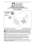
Figure 3A on the following page provides a general overview of the furnace components and their
proper assembly.
Required Tools and Materials
The following tools are required for furnace assembly and should be gathered before starting any procedures:
•
•
•
•
•
•
3/8" open-end wrench
9/16" open-end wrench
Medium flat-blade screwdriver
Medium adjustable wrench
1/4" nut driver attachment for drill
Variable speed drill
3-1
Operator's Manual: Models CB-1500 & CB-2500 (230 V / 50 Hz)
"ALL THREAD" RODS
COUPLINGS FOR "ALL THREAD" RODS
JUNCTION BOX
BURNER
CABLE
4
BURNER
MOUNTING
BRACKET
THROAT
Danfoss
Type BHO 64
Nr. 05 7H7036
220-2 40V 5 0-60Hz 3W
ts 10s
R.H.
FURNACE
BREECH
FURNACE DOOR
AIR
OIL
5
LH FURNACE
BREECH WITH
CLEAN−OUT
1
NOTE: LOOP ON ENERGY RETENTION
DISC HOOKS OVER MOUNTING
BRACKET ON BACK WALL OF
COMBUSTION CHAMBER
3
ENERGY
RETENTION DISC
INSTALLED ON
BACK WALL OF
COMBUSTION
CHAMBER
2
HOT AIR DISCHARGE
FURNACE BREECH
NOTICE THE VARIOUS MOUNTING CHOICES FOR THE LOUVERS
IT IS OK TO OPEN OR RESTRICT THE LOUVERS AS NEEDED, AND THEN
TO TURN THOSE CONFIGURATIONS IN ANY OF FOUR DIRECTIONS
I88943
Complete assembly of the CB-1500/CB-2500 furnace according to the following list of activities as
illustrated above:
(1) Installing the Blower Assembly
(2) Installing the Hot Air Discharge Components
(3) Installing the Energy Retention Disc
(4) Installing the Burner
(5) Installing the Connector Block, Oil Line Tubing, and Air Line Tubing
NOTE: Corresponding procedures provided in order in this section.
Figure 3A - Overview of 2500 Furnace Assembly (CB-1500 is similar)
3-2
Operator's Manual: Models CB-1500 & CB-2500 (230 V / 50 Hz)
Installing the Blower Assembly
1.
2.
3.
4.
5.
Refer to Figures 3B and 3C.
Remove the blower stabilizer brackets as shown in Figure 3B. (These braces, which are installed
at the factory, are designed to keep the blower in proper position during shipping. Note that
these braces are provided on CB-2500 blower assemblies ONLY; CB-1500 blower assemblies do
not require these special shipping braces.)
Position the blower over the opening in the back of the furnace cabinet by sliding the blower into
the mounting angle brackets. Note that the mounting brackets may be loosened for adjustment,
as needed. The blower should be centered over the opening.
Fasten the blower to the brackets with self-tapping screws (provided). Drive the screws into the
blower housing through the holes in the mounting angle brackets. There are four holes along each
side and across the top of the bracket to fasten the blower to the furnace cabinet.
Install the blower safety guards as shown.
WARNING: To avoid serious personal injury, be sure to install both pieces of the blower guard
around the blower prior to operating the furnace. NEVER operate the furnace without all safety
shields/guards in place!
ATTENTION: The air flow is changed when the guards are not in place which may result in damage
to the blower motor.
NOTE: For proper air flow through the furnace cabinet the blower must be positioned so that the
bulge on the blower faces down as illustrated in Figures 3A, 3B, and 3C.
1 REMOVE SHIPPING BRACES
2 ATTACH BLOWER TO FURNACE
3
X2
I88691−D
Figure 3B - Installing the Blower Assembly
3-3
Operator's Manual: Models CB-1500 & CB-2500 (230 V / 50 Hz)
Installing the Blower Assembly (continued)
Black Motor Lead − Orange Wire
White Motor Lead − White Wire
Brown Motor Leads − Capacitor
Green Wire − Ground Screw
Note: CB-1500 is shown; CB-2500
Junction Box and Motor are mounted
on the opposite side of the blower.
I89017
Figure 3C - Blower Installed on Furnace Cabinet
Wiring the Blower Motor
WARNING: Make sure the main power to the furnace is turned OFF before wiring the blower
motor.
NOTE: For reference, wiring schematics are provided in Appendix B at the back of the manual.
1.
After the blower has been secured to the back of the furnace cabinet, install the electrical conduit
with the blower motor leads into the 4" x 6" rear junction box on the top of the furnace cabinet as
shown in Figure 3C.
•
•
•
•
Connect the power lead coming from the blower assembly to the 4" x 6" electrical box
mounted on the rear of the furnace cabinet.
Connect the black (power) motor lead wire to the connector block terminal with the orange
(power) wire from the front electrical box.
Connect the white (neutral) motor lead wire to the connector block terminal with the
white (neutral) wire from the front electrical box.
Connect the two brown leads to the capacitor and mount it inside the electrical box with the
strap provided.
3-4
Operator's Manual: Models CB-1500 & CB-2500 (230 V / 50 Hz)
Determining the Hot Air Discharge Configuration
Before proceeding with the assembly of your furnace, it is important to determine the configuration of the air
discharge for your furnace. There are three configurations to consider for the CB-2500 and two possible
configurations for the CB-1500:
(1) Unit Heater
CB-1500 and
CB-2500
Furnace with blower assembly for FREE AIR applications.
Follow the instructions (provided in this section) to install the blower
assembly and air discharge components. Be sure to adhere to the proper
specified clearances for Unit Heater Configurations as stated in
Section 4 of this manual.
CB-1500 Equipped with two (2) louver sections and four (4) blank cover panels
CB-2500 Equipped with three (3) louver sections and three (3) blank cover panels
(2) Central Furnace (A)
CB-1500 and
CB-2500
Furnace with blower assembly for DUCTING applications with 0.06 kPa
(0.25 "WC) or less static pressure.*
Follow the instructions to install the blower assembly, and refer to the
following chart for the proper air discharge and ducting specifications.
Be sure to adhere to the proper specified clearances for Central Furnace
Configurations as stated in Section 4 of this manual.
CB-1500 Do not install louvers. Ductwork should be installed directly over the desired
air discharge opening on the side of the furnace cabinet (305 mm x 305 mm).
CB-2500 Determine which side of the furnace cabinet will have the ductwork attached.
Replace the left or right side inner shield and shrouding to accommodate the
ductwork. Do not install louvers. Ductwork should be installed directly over
the desired air discharge opening on the side of the furnace cabinet
(395 mm x 395 mm).
#29184 Inner Shield Right
#29186 Right Side Shrouding
#29185 Inner Shield Left
#29187 Left Side Shrouding
Install an additional blank cover panel to close off the remaining air discharge
opening.
#29115 Cover Discharge Closure Panel
(3) Central Furnace (B)
CB-2500 ONLY
Furnace with blower assembly for DUCTING applications from 0.06 kPa
(0.25 "WC) to 0.10 kPa (0.40 "WC) static pressure.*
Follow the instructions to install the blower assembly, and refer to the
following chart for the proper air discharge and ducting specifications.
Be sure to adhere to the proper specified clearances for Central Furnace
Configurations as stated in Section 4 of this manual.
CB-2500 Same as above - Central Furnace (A)
3-5
Operator's Manual: Models CB-1500 & CB-2500 (230 V / 50 Hz)
Determining the Hot Air Discharge Configuration (continued)
Air Flow - Cubic Meters per Minute (CMM) or Cubic Feet per Minute (CFM)
and Static Pressure (SP) Specifications
CB-1500
Air Discharge Louvers
Mounted on Furnace
Air Discharge Louvers Removed
With Ductwork Installed on Furnace
Free Air*
0.06 kPa*
(0.25 INCHES WC)
40 CMM
(1400 CFM)
34 CMM
(1200 CFM)
CB-2500
Air Discharge Louvers
Mounted on Furnace
Air Discharge Louvers Removed
With Ductwork Installed on Furnace
Air Discharge Louvers Removed
With Ductwork Installed on Furnace
Free Air*
0.06 kPa*
(0.25 INCHES WC)
0.10 kPa*
(0.40 INCHES WC)
71 CMM
(2500 CFM)
68 CMM
(2400 CFM)
64 CMM
(2250 CFM)
*ATTENTION: A qualified electrician must check the blower motor amperage during operation of the furnace to ensure that
motor amperage does not exceed 85% of the maximum amperage on the motor label. DO NOT operate the blower motor above
85% of maximum amperage or motor damage may occur.
IMPORTANT NOTE: It is essential that qualified HVAC personnel properly design the ductwork
for your furnace and determine the static pressure for your ducting application. Note that existing
ductwork at your installation site may not be appropriate or meet the specifications for this
furnace installation. For static pressure readings as shown in the chart above, the ductwork
should be installed directly over the opening in the SIDE of the furnace cabinet (i.e. where the
louver panels would be installed for free air applications.) For Central Furnace applications,
ductwork may NOT be installed over the bottom opening.
Installing the Hot Air Discharge Components
It is very important to properly install the hot air discharge components (louvers and blank cover panels) to
direct the flow of air from the furnace. As you will note from Figures 3D and 3E, the air discharge panels are to
be installed on the side(s) and/or bottom of the furnace. The air flow may be directed down, front, or back
depending on how the louvers and cover panels are installed.
IMPORTANT NOTE FOR CENTRAL FURNACE APPLICATIONS:
• For ducting applications with static pressure, DO NOT install the louvers. The ductwork should
be installed directly over the desired air discharge opening on the side of the furnace cabinet.
CB-1500 opening in side shrouding for ductwork - 305 mm x 305 mm (12" x 12")
NO changes need to be made for the shrouding outlet size
CB-2500 opening in side shrouding for ductwork - 395 mm x 395 mm (15 1/2" x 15 1/2")
Install new inner shield and outside shrouding with larger opening sizes
• Ductwork must be installed over side opening(s) ONLY. Ductwork may NOT be installed over
the bottom air discharge opening.
3-6
Operator's Manual: Models CB-1500 & CB-2500 (230 V / 50 Hz)
Installing the Hot Air Discharge Components (continued)
1.
2.
3.
4.
Refer to Figures 3D and 3E. Determine the desired air flow discharge pattern. Note that the
CB-1500 is supplied with (2) louver sections and (4) blank cover panels. The CB-2500 is supplied
with (3) louver sections and (3) blank cover panels. Air discharge openings are: (1) on each side of
the furnace, and (1) on the bottom of the furnace.
Install the louver panels in the desired location(s) with the self-tapping screws provided. Holes
are pre-drilled in the furnace cabinet to accommodate installation of the panels.
Adjust the louvers for the desired air flow direction.
ATTENTION: DO NOT restrict the flow of the hot air from the furnace by closing the louvers,
or the furnace will not operate properly.
Install the blank covers over the remaining air discharge opening(s) on the furnace cabinet.
Air Flow Discharge Installation
Guidelines:
•
When determining the
placement of the air discharge
louvers, you also need to consider
the required clearances from
combustibles as stated in
Section 4 of this manual.
•
Note that the CB-1500 is
supplied with (2) louver sections
which may be installed together
on one side or the bottom OR the
louvers may be split for partial air
discharge on each side and/or
bottom. If a side contains only
one louver section it should be
mounted on the upper portion.
2 20
D
-2 40
50-6
3W
0Hz ts 10s
ss
anfo
64
6
e BHO 03
T yp 05 7H7
Nr.
NOTE: Bottom louver installation
applies to Unit Heater furnaces ONLY.
Ductwork for Central Furnace applications
may NOT be installed over the bottom
opening.
Danfos
s
Ty p
Nr. e BHO
0 57
H70 6 4
36
2 20
-2
40
50
-6 0Hz
ts 1
CB-2500 IS SHOWN
(CB-1500 IS SIMILAR)
3W
0s
I88944
Figure 3D - Hot Air Discharge Components (Louvers/Blank Covers) Installed on Furnace
3-7
Operator's Manual: Models CB-1500 & CB-2500 (230 V / 50 Hz)
Installing the Hot Air Discharge Components (continued)
Louvers split between two side openings, showing left and right side views of same furnace
NOTE: When louver panels are "split" between two sides, make sure the louvers are installed
in the upper half of each side air discharge opening as shown here.
Louvers split between left side and bottom openings, showing left and right side views of same furnace
NOTE: When louver panels are "split" between a side and the bottom, make sure the bottom louvers
are installed in the forward half of the bottom air discharge opening as shown here.
Louvers split between both sides and bottom openings, showing left and right side views of same furnace
I88945
Figure 3E - Sample Split Louver Installations for Partial Air Discharge on Sides and/or Bottom.
CB-2500 is shown. CB-1500 is similar with two (2) louver sets and four (4) blank cover panels.
3-8
Operator's Manual: Models CB-1500 & CB-2500 (230 V / 50 Hz)
Installing the Energy Retention Disc
Installing the Energy Retention Disc at the Back of the Combustion Chamber
ATTENTION: DO NOT fire your furnace without the Energy Retention Disc in place, or combustion chamber damage will occur. Handle the Energy Retention Disc carefully to avoid damaging it.
1.
2.
3.
Refer to Figure 3A to review the proper positioning of the Energy Retention Disc.
Swing open the clean-out door on the furnace front to gain access to the combustion chamber.
Use a long rod to support the Energy Retention Disc as you guide it into position on the back of the
combustion chamber. The loop on the back of the Energy Retention Disc fits over the hook located on
the back of the combustion chamber.
Closing the Furnace Door
1.
2.
After the Energy Retention Disc has been installed, close the furnace clean-out door.
Tighten the four (4) lock-down nuts in a criss-cross pattern until all are snug.
Installing the Burner
Checking the Burner Nozzle and Electrodes
NOTE: The burner nozzle is factory installed. Both furnace models (CB-1500, CB-2500) use a Delavan
9-5 nozzle. The nozzle size is indicated on the nozzle as shown in Figure 3F on the following page. Refer also
to Appendix A at the back of the manual for additional specifications/instructions on the burner nozzle.
ATTENTION: Check the electrode settings as specified in Figure 3F. The electrode settings must be
correct for your burner to operate properly.
3-9
Operator's Manual: Models CB-1500 & CB-2500 (230 V / 50 Hz)
Installing the Burner (continued)
BURNER NOZZLE
NOZZLE IS STAMPED WITH SIZE
ON FLAT OF NOZZLE HEAD
SIDE VIEW − AA
5 mm (3/16") GAP BETWEEN
ELECTRODES & NOZZLE
3X
CRITICAL DIMENSION:
NOZZLE MUST BE 3 mm
(1/8") AHEAD OF THE
DISK. NOZZLE MUST NOT
BE BEHIND THE DISK.
VIE
W
−B
B
W
VIE
A
−A
3 mm (1/8")
SPARK
GAP
FRONT VIEW − BB
I88906
Figure 3F - Burner Nozzle and Electrode Specifications
3-10
Operator's Manual: Models CB-1500 & CB-2500 (230 V / 50 Hz)
Installing the Burner (continued)
Mounting the Burner on the Hinge Bracket
ATTENTION: Burner tube components (e.g. electrodes and retention head) are factory set. Handle the
burner with extreme care so that burner components are not damaged.
1.
Remove the nut from the mounting flange of the furnace cabinet, and set it aside for later use.
2.
Lift the burner into position so that it is mounted on the hinge bracket on the furnace cabinet.
3.
Carefully swing the burner so the retention head enters the throat of the furnace.
4.
Check the clearance between the retention head and the furnace throat. There must be at least
1/8" clearance, so the retention head is not "bumped" as you swing the burner into firing
position.
NOTE: If the retention head "bumps" the furnace throat, adjust the hinge bracket bolts
as follows:
• While supporting the burner, slightly loosen the two (2) hinge bracket bolts.
• Carefully re-position the burner so it swings freely into its firing position.
• With the burner in its firing position, re-tighten the hinge bracket bolts.
3-11
Operator's Manual: Models CB-1500 & CB-2500 (230 V / 50 Hz)
Installing the Connector Block, Oil Line Tubing, and Air Line Tubing
ATTENTION: DO NOT use teflon tape on any fittings. Teflon tape residues will plug vital burner
components.
Installing the Connector Block on the Furnace Door
OIL LINE
1.
2.
3.
Refer to Figure 3G.
Use the two (2) bolts to install the aluminum
connector block onto the furnace cabinet.
Remove and discard the red caps and plugs from the
fittings and ports on the connector block. DO NOT
allow any dirt/debris to enter these components
during furnace assembly.
ATTENTION: The connector block includes an
accumulator. The accumulator functions like a shock
absorber on the oil line to prevent pressure buildup and
protect vital burner components. It is important that the
connector block is installed as shown so that the accumulator
is in a vertical position to prevent sediment from settling in
the accumulator. Never operate your furnace without the
connector block and accumulator properly installed on the
furnace, or damage may occur to vital burner components.
OIL FITTING
ON BURNER
Danfoss
Type BHO 64
Nr. 057H7036
220-240V 50-60Hz 3W
ts 10s
CONNECTOR BLOCK
AIR
OIL
FRONT VIEW OF FURNACE
OIL LINE FITTING
ON BURNER LINED
UP WITH OIL LINE
OIL LINE
Installing the Oil Line Tubing
ATTENTION: DO NOT disassemble the compression
fitting from the swivel fitting. To prevent leaks, the NPT
threads of the compression fitting have been sealed with
hydraulic sealant during assembly of the fittings at the
factory.
1.
2.
3.
4.
SWIVEL
ASSEMBLY
CONNECTOR
BLOCK
SIDE VIEW OF FURNACE
SHOWING OIL LINE INSTALLED
I88886
Remove and discard the red caps from the oil line
tubing.
Figure 3G - Installation of Connector
Loosely install the oil line tubing into the oil line
Block and Oil Line
fitting on the burner.
Use a wrench to slightly rotate the oil line fitting on the burner counterclockwise so the tubing
lines up with the swivel assembly. Slightly bend the tubing as shown in Figure 3H, if required,
to "line up" the oil line.
If necessary, use a tubing cutter to cut the tubing to the proper length.
ATTENTION: Due to adjustment of the burner hinge bracket, the oil line tubing may need to
be cut to fit properly. DO NOT lift up on the burner when installing the oil line tubing to
compensate for oil line tubing that is too long. This will place the weight of the burner on the
swivel fitting and result in leaks at the swivel fitting seal.
3-12
Operator's Manual: Models CB-1500 & CB-2500 (230 V / 50 Hz)
Installing the Connector Block, Oil Line Tubing, and Air Line Tubing
(continued)
Installing the Oil Line Tubing (continued)
5.
6.
Make sure that the curl in the oil line is positioned as shown in Figure 3G so that the burner can
swing open correctly.
Install the oil line tubing and tighten the nuts on the compression fittings. DO NOT overtighten
these fittings to avoid damaging the ferrules.
NOTE: You may also check the positioning of the oil line according to Figure 3H which provides a
larger front view of the connector block assembly.
Installing the Air Line Tubing
1.
2.
3.
Remove and discard the red caps from the air line tubing.
Refer to Figure 3H. Push the air line tubing into the swivel fitting on the connector block until
the tubing bottoms out in the fitting.
Repeat this procedure to connect the air line tubing to the air line fitting on the side of the burner.
CB-1500 is shown
CB-2500 is similar
AIR LINE FITTING
ON BURNER
OIL LINE FITTING
ON BURNER
Danfoss
Type BHO 64
Nr. 057H7036
220-240V 50-60Hz 3W
ts 10s
AIR LINE
OIL LINE
COMPRESSION /
SWIVEL FITTING
AIR
OIL
CONNECTOR BLOCK
INSTALLED ON
FURNACE CABINET
I88887
Figure 3H - Installation of Connector Block, Oil Line and Air Line (Front View)
3-13
Operator's Manual: Models CB-1500 & CB-2500 (230 V / 50 Hz)
Locking the Burner Into Firing Position
1.
2.
3.
4.
Swing the burner into firing position.
Install and tighten the lock-down nut on the mounting
plate bolt to secure the burner in its firing position.
Plug the burner electrical cable into the receptacle on the
top of the burner housing.
Tighten the locking ring to secure the electrical cable.
PLUG ON CAM
LOCK CABLE
NOTE: Be sure to properly align the plug when plugging it into
the receptacle. See Fig 3I.
SLOT IN PLUG
MUST ALIGN WITH
SLOT IN
RECEPTACLE
RECEPTACLE ON
TOP OF BURNER
I88354A
Figure 3I - Detail of Burner
Electric Receptacle
NOTE: Your furnace is now assembled and ready for installation. Install the furnace
as soon as possible so the burner and/or blower are not "bumped" or damaged. If you
must store the furnace for a period of time before installation, make sure it is located in a
safe, secure area.
3-14
Operator's Manual: Models CB-1500 & CB-2500 (230 V / 50 Hz)
SECTION 4: FURNACE INSTALLATION
Understanding Installation
Installing your Clean Burn furnace is a multi-step process which includes:
(1) Selecting a Location
(2) Mounting the Furnace
(3) Oil Tank Installation Specifications (review)
(4) Installing the Metering Pump
(5) Wiring the Furnace and Pump
(6) Installing the Oil Lines
(7) Installing the Compressed Air Line
(8) Installing the Stack
(9) Installing the Wall Thermostat
(10) Inspecting the Installation
Clean Burn recommends that you review all procedures before beginning installation, paying careful
attention to safety information statements. Figures 4A and 4B provide a general overview of a typical furnace
installation and should be reviewed closely before proceeding.
WARNING: Improper installation can adversely affect the proper, safe operation of your
furnace. It is critical that your furnace installer reads and follows the instructions provided in this
manual. Access to the furnace must be restricted; only trained, qualified personnel should be permitted
to perform installation and operation procedures.
WARNING: To prevent damage to the furnace and to ensure personal safety, lifting, mounting,
and hanging of the furnace must be performed in accordance with safe handling procedures.
Important Safety Guidelines for Safe Installation
General installation of the appliance shall be in accordance with the manufacturer's literature, in addition
to complying with the following:
BS5410
Code of Practice for Oil Firing
1997: Installation up to 45 KW output capacity for space heating and hot water supply
purposes.
1998: Installation of 44 KW and above capacity for space heating, hot water and steam
supply purposes.
1978: Installation for furnaces, kilns, ovens and other industrial purposes.
The Building Regulations:
England and Wales: Approved Document J: Heat Producing Appliances (1991).
Scotland: Technical standards for compliance with the Building Standard (Scotland) Regulations
1990, Part F: Heat Producing Installations and Storage of Liquid and Gaseous Fuels.
Northern Ireland: The Building Regulations (Northern Ireland) 1990. Technical Booklet L Heat Producing Appliances, July 1991.
Republic of Ireland: The Building Regulations of Ireland 1997, Part J: Heat Producing
Appliances.
Isle of Man, Jersey and Guernsey: The Building Bylaws - BS 7671: 1992 IEE Wiring
Regulations 16th Edition.
4-1
Operator's Manual: Models CB-1500 & CB-2500 (230 V / 50 Hz)
Important Safety Guidelines for Safe Installation (continued)
The Environmental Protection Act 1990, Part 1: Processes prescribed for air pollution control by
local enforcing authorities PG1/1 (95).
Secretary of State's Guidance: Waste Oil Burners, less than 0.4 MW net rated thermal input.
November 1995 (Appendix A of OFTEC OFSA 103).
OFTEC Guidelines: Document OFG100 for externally serviced oil fired appliances.
Important Notes to the Electrician
WARNING: Electrical installation of the furnace is to be performed only by qualified personnel
(i.e. licensed electrician/engineer). Improper electrical installation can adversely affect the
proper, safe operation of the furnace and may cause serious personal injury/death.
WARNING: Before completing any furnace wiring, refer to the wiring diagrams in Appendix B
at the back of the manual. Carefully review the wiring assignments and colors, noting that the
Clean Burn wire colors may not be "standard" or familiar.
WARNING: High earth leakage current / earth connection is essential and must be established
before connecting the main power supply.
WARNING: Low voltage terminals are only protected by basic insulation--caution is required.
CAUTION: Use only approved wire conduit and connectors when wiring the Clean Burn
furnace. An emergency stop device (i.e. "panic button") must be installed at ground level in the
mains cable to the furnace to ensure the safety of furnace operators and service personnel. The external
disconnect device must employ a contact separation of 3mm in all poles; the external breaker must be an
approved type.
CAUTION: The main cable must be introduced into the control box using conduit connectors
which provide adequate strain relief. The main cable installation must be accomplished using suitably
rated and approved wiring (BASEC or HAR) or appropriate current-carrying capacity. The wires should have
a minimum rating of 90 degrees C.
NOTE: According to Clause 4A of 61000-3-11 (International Electrical Standard), the user must
determine, in consultation with the supply authority, that the furnace is connected only to a supply with
an impedance of 3.773 x 10⁻³ + 2.358 x 10⁻³ or less.
4-2
Operator's Manual: Models CB-1500 & CB-2500 (230 V / 50 Hz)
(2 FT)
NOTE: THE LAST STACK SECTION SHALL EXTEND AT LEAST 92 cm (3 FT)
ABOVE THE HIGHEST POINT AT WHICH IT COMES IN CONTACT WITH THE
ROOF, AND AT LEAST 61 cm (2 FT) HIGHER THAN ANY RIDGE, PARAPET
OR ROOF STRUCTURE WITHIN 3 m (10 FT) OF IT.
61 cm
WARNING! NEVER LOCATE A STACK JOINT INSIDE WALLS OR IN A JOIST
SPACER. DO NOT CREATE FIRE HAZARDS!
WARNING! FOLLOW LOCAL
CODES AND STACK
MANUFACTURER’S
SPECIFICATIONS TO ENSURE
SAFE CLEARANCES BETWEEN
STACK COMPONENTS AND
COMBUSTIBLES
3m
3 m (10 FT) MIN. VERTICAL STACK HEIGHT
(10 FT)
WARNING: When installing
your furnace, adhere to the
clearances from
combustible surfaces as
stated in Section 4,
Dan foss
T ype BHO 64
Nr. 057 H7036
22 0-240V 50-6 0Hz 3W
ts 10s
STACK SIZE:
MIN. 20 cm (8 IN.)
CONNECTOR BLOCK
AIR
OIL
CLEAN BURN RECOMMENDS THAT
HORIZONTAL STACK NOT EXCEED 60% OF
VERTICAL STACK LENGTH
CAUTION: DO NOT EXCEED 183 cm (6 FT)
VERTICAL SUCTION LIFT OR THE PUMP WILL
NOT PRIME AND/OR THE FLOW RATE FROM
THE PUMP MAY DECREASE
COMPRESSED AIR LINE
MAXIMUM 183 cm (6 FT)
244 cm (8 FT) MIN. FROM FLOOR TO FURNACE IF THERE IS A POTENTIAL FOR
GASOLINE FUMES IN YOUR SHOP. CHECK LOCAL CODES.
These clearances also provide
adequate space for servicing.
Failure to maintain proper
clearences may result in fire,
explosion, personal injury or
death.
BALL VALVE
FUNNEL WITH
BALL VALVE
RADIAL BEND MADE
WITH TUBING BENDER
VENT
CAP
EMERGENCY
VENT VALVE
CONTINUOUS PIECE
OF COPPER TUBING
INSIDE TANK:
16 mm (5/8") O.D.
INSTALL SLIP FITTING
TO HOLD TUBING
IN PLACE
CHECK VALVE IS MINIMUM
305 mm (12 IN.) OFF TANK
BOTTOM TO CREATE SLUDGE TRAP
I88890−B
Figure 4A - Typical CB-2500 Furnace Installation (CB-1500 is similar)
4-3
Operator's Manual: Models CB-1500 & CB-2500 (230 V / 50 Hz)
NON−RESTRICTIVE
"CLASS A" STACK CAP
"CLASS A" STACK INSULATED STACK
WITH STAINLESS STEEL LINER
WARNING! OUTSIDE STACK AND
STACK PENETRATIONS THROUGH
CEILING, ROOF OR SIDEWALL MUST
BE "CLASS A" FOR FIRE SAFETY AND
TO MAINTAIN PROPER DRAFT
WARNING! MAKE SURE TO INSTALL
THE PROPER ROOF SUPPORT
SYSTEM TO SAFELY SUPPORT THE
STACK
EXTERIOR SINGLE WALL STACK
DOES NOT MEET CODE. EXTERIOR
SINGLE WALL STACK CHILLS THE
EXHAUST GASES RESULTING IN
POOR BURNER PERFORMANCE AND
BACK PRESSURE IN THE FURNACE
CEILING MOUNTING SYSTEM
WATERTIGHT ROOF FLASHING:
CLEAN BURN RECOMMENDS "DEKTITE"
FLASHING FOR A WATERTIGHT SEAL
WARNING! USE MINIMUM 64 mm X 64 mm X 6 mm
(2−1/2 X 2−1/2 X 1/4") ANGLE IR0N BEAMS,
BRIDGED ACROSS SUFFICIENT
ANGLE IRON SUPPORT
STRUCTURAL MEMBERS TO
SAFELY SUPPORT FURNACE
BEAMS
DOUBLE NUTS
(4) 5/8 "ALL THREAD" SUPPORT RODS
"CLASS A" KIT FOR
INSTALLING
"CLASS A" STACK
THROUGH
CEILING
THREAD SUPPORT RODS TO COUPLING
NUTS IN FURNACE CABINET
WARNING! MAKE SURE TO USE LOCKNUTS
WHEN FASTENING THE RODS TO THE
COUPLING NUTS
SINGLE WALL STACK
MINIMUM 24 GAUGE
BAROMETRIC DAMPER:
INSTALL ON STACK
305 mm (1 FT) TO
915 mm (3 FT)
FROM FURNACE
BREECH
T ype BHO 64
Nr. 057H7036
CHECK FOR −.02 W.C.
DRAFT OVERFIRE AT
SIGHT PLATE
1/4" HOLE FOR
SETTING DRAFT.
ADJUST BAROMETRIC
DAMPER FOR −.04 W.C.
DRAFT AT BREECH
22 0-2 40V 5 0- 60Hz 3W
ts 10s
R. H.
FURNACE
BREECH
CONNECTOR BLOCK
AIR
L.H. FURNACE
BREECH WITH
CLEAN−OUT CAP
INSTALLED
ELBOW OR
CLEAN−OUT TEE
OIL
OIL FLOW
"2 WIRE" MIN 18 GA.
THERMOSTAT CABLE
DEDICATED ELECTRIC CIRCUIT
Danfoss
OIL PUMP ELECTRICAL CIRCUIT
AIR DISCHARGE
COMPRESSED AIR LINE
PRESSURE OIL LINE
24 VOLT WALL
THERMOSTAT
FUNNEL WITH
BALL VALVE
ELECTRIC SERVICE
BALL VALVE
SUCTION LINE
CAUTION: SUCTION OIL LINE MUST BE 100%
AIRTIGHT. AIR LEAKS CAUSE THE BURNER TO
PERIODICALLY SHUT DOWN ON SAFETY LOCKOUT
FLARE FITTING
CANISTER FILTER
IN SUCTION LINE
NOTE:
MAKE SURE
IS IN THE SAME
DIRECTION AS
EMERGENCY
VENT VALVE
VENT PIPE
WITH VENT
CAP
CHECK VALVE
INSTALL WITH
ARROW UP
CHECK VALVE SCREEN
CLEAN OUT
OIL STORAGE TANK
I88891−B
Figure 4B - Typical CB-2500 Furnace Installation - Detailed (CB-1500 is similar)
4-4
Operator's Manual: Models CB-1500 & CB-2500 (230 V / 50 Hz)
Selecting a Location
Guidelines for Selecting a Location
The location you select for your furnace must allow the following:
• Unobstructed, even heat distribution.
• Safe, easy access for servicing.
• Unobstructed passage for shop vehicles and equipment.
• Proper clearances from combustibles. Verify according to your local safety codes.
• Adequate combustion air per local codes.
• Proper stack installation.
WARNING: Adhere to the following minimum clearances from combustible surfaces and
to provide adequate clearance for servicing (also refer to Figure 4C); failure to maintain proper clearances may result in fire, explosion, personal injury or death.
CLEARANCES FOR UNIT HEATER INSTALLATION
WITH SIDE AIR DISCHARGE
•
•
•
•
•
•
•
TOP (of furnace) ......................... 31 cm
FRONT (burner) ......................... 153 cm
SIDE with Air Discharge ............ 153 cm
OTHER SIDE ............................. 46 cm
CHIMNEY CONNECTOR ........... 46 cm
REAR (from blower) ................... 5 cm
BOTTOM ................................... 61 cm
(12")
(60")
(60")
(18")
(18")
(2")
(24")
CLEARANCES FOR UNIT HEATER INSTALLATION
WITH BOTTOM AIR DISCHARGE
• TOP (of furnace) ............................... 31 cm (12")
• FRONT (burner) ............................... 153 cm (60")
• SIDE (with or without stack) ............. 153 cm (60")
• CHIMNEY CONNECTOR ................. 46 cm (18")
• REAR (from blower) ......................... 5 cm
(2")
• BOTTOM with Air Discharge ............ 97 cm (38")
CLEARANCES FOR CENTRAL FURNACE
INSTALLATION
•
•
•
•
•
•
•
TOP (of furnace) ......................... 31 cm
FRONT (burner) ......................... 153 cm
SIDE without stack .................... 46 cm
CHIMNEY CONNECTOR ........... 46 cm
REAR (from blower) ................... 5 cm
BOTTOM ................................... 61 cm
WARM AIR DUCTS . ................ 15 cm
within 92 cm (3ft)
WARNING: Your local codes may
require that your furnace is mounted a
minimum of 244 cm (8 ft.) off the ground if there is
the possibility of gasoline fumes or other
combustible or explosive fumes in your shop area.
(12")
(60")
(18")
(18")
(2")
(24")
(6")
Refer to Figure 4C on the following page for an illustration of proper clearances from combustibles.
4-5
Operator's Manual: Models CB-1500 & CB-2500 (230 V / 50 Hz)
Selecting a Location (continued)
5 cm (2")
REAR
31 cm (12")
TOP
46 cm (18")
OTHER SIDE
(WITHOUT AIR
DISCHARGE)
50 -60
46 cm (18")
CHIMNEY
CONNECTOR
3W
Hz 1 0s
ts
40
2 2 0-2
oss
Danf
64
BHO 6
pe 7 H703
Ty 05
Nr.
153 cm (60")
FRONT
153 cm (60")
AIR DISCHARGE
SIDE
244 cm (96") BOTTOM, IF THERE IS POTENTIAL
FOR GASOLINE FUMES
61 cm (24") BOTTOM, IF THERE IS NO
POTENTIAL FOR GAS FUMES
(NOTE: 97 cm (38") FOR BOTTOM
AIR DISCHARGE)
I88946
Figure 4C - Clearances from Combustibles
Mounting the Furnace
After selecting a safe and appropriate location for your furnace, construct the mounting system as
required by the location and the following specifications.
Ceiling Mounting
WARNING: To prevent serious personal injury, ensure that your furnace mounting system can
safely bear the suspended weight of the furnace and allow safe servicing of furnace components.
Use adequately sized square tubing or angle iron bridged across sufficient structural members to safely support
the furnace.
1.
2.
3.
Refer to Figures 4A and 4B.
Follow the instructions as provided in the diagrams.
Use a spirit level to make sure the cabinet is level side to side and front to back.
4-6
Operator's Manual: Models CB-1500 & CB-2500 (230 V / 50 Hz)
Mounting the Furnace (continued)
Raised Platform Mounting
WARNING: To prevent serious personal
injury, make sure the platform is designed to
safely bear the weight of the furnace and allow safe
servicing of furnace components. The platform
must be constructed of non-combustible materials
(e.g. steel) and must be securely anchored to an
adjacent wall.
1.
Danfo ss
Typ e BHO 6 4
Nr. 0 57 H7 036
2 20 -2 4 0V 5 0- 60 Hz 3 W
ts 10 s
AIR
O IL
Refer to Figure 4D, and follow the
instructions as provided in the diagram.
Floor Mounting
WARNING: To prevent serious personal injury,
make sure the floor can safely bear the weight of
the furnace.
CAUTION: If you are installing your furnace
in an area with a combustible floor, you must
construct a non-combustible floor as shown in
Figure 4E.
NOTE: Make sure that blank cover panels are
installed over the bottom air discharge opening to allow
safe floor mounting.
1.
Refer to Figure 4E and follow the instructions
as provided in the diagram.
I88893
Figure 4D - CB-1500 Furnace Installed on a
Raised Platform (CB-2500 is similar)
Danfoss
Ty pe BHO 64
Nr. 057H7036
MIN. 24 GA STEEL
PAN WITH MIN. 2.5 cm
(1") LIP FOR
OIL CONTAINMENT
46 cm (18")
220-240V 50-60Hz 3W
ts 10s
AIR
OIL
46 cm (18")
20 cm (8") MIN.
TALL CINDER BLOCK
1 PIECE
MIN. 24 GA STEEL
2 PIECES FIREGUARD
SHEETROCK OR EQUIVALENT
COMBUSTIBLE MATERIAL
MIN. 5 cm (2") TALL MASONRY BLOCKS TO
ALLOW CLEARANCE FOR INSTALLATION OF
FITTINGS ON THE CONNECTOR BLOCK
I88894
Figure 4E - CB-1500 Furnace Installed on Non-Combustible Floor (CB-2500 is similar)
4-7
Operator's Manual: Models CB-1500 & CB-2500 (230 V / 50 Hz)
Oil Tank Installation Specifications
Ensure that your tank installation adheres to the
following safety guidelines as stated here and in
Section 1 of this manual.
The tank safety label (shown at right) also
summarizes these important specifications for tank
installation and usage. If you do not have a copy of
this label, please contact your Clean Burn dealer for
a copy, which is to be affixed directly to your used
oil supply tank.
•
•
•
•
•
•
•
•
The tank installation must meet all
national and local codes. Consult your
local municipal authorities for more
information as necessary.
Use a minimum 1000 Liter tank. DO NOT
use drums as a substitute for an appropriate
tank. The tank must be large enough to allow
water, sludge, etc. to settle out of the used oil.
Single wall tanks must have a shut-off
valve on the side of the tank to allow
the water, sludge, etc. to be drained from
the bottom of the tank.
All unused openings in the tank must be
plugged or capped off.
For optimal system functioning, Clean Burn
Recommends inside tank installations as
shown in Figures 4A, 4B, and 4J.
The tank must be vented to the outside of
the building using iron or steel pipe and
fittings with an approved vent cap.
Carefully review the oil tank and pump
installation details as shown in Figures 4A,
4B, 4F, and 4J including the metering pump
installation and specifications for the oil
line installation. (Procedures for installing
these components can be found in the
following pages.)
Ensure that the oil supply tank is properly
maintained; refer to Section 9 in this manual
for related procedures.
ATTENTION: For outside tank installations and/or tanks larger than 1890 Liters (500 gallons),
contact the local Clean Burn distributor for installation recommendations and specifications.
4-8
Operator's Manual: Models CB-1500 & CB-2500 (230 V / 50 Hz)
Oil Tank Installation Specifications (continued)
TANK VENT KITS AVAILABLE FROM CLEAN BURN:
CB Part # 70380 − 4" Tank Vent Kit
(2) elbows
(2) 6" nipples
(1) mushroom cap vent
(1) emergency vent
PRESSURE
PRESSURE
LINE
RELIEF OIL
LINE BACK TO
THE TANK
PUMP
MUSHROOM
CAP VENT
STEEL PIPE
(USER SUPPLIED)
SUCTION LINE
ASSEMBLY
FUNNEL WITH
BALL VALVE
EMERGENCY
VENT
CHECK
VALVE
FILTER
SCREEN
CLEAN−OUT
(TANK DRAIN)
Figure 4F - Typical Metering Pump Installation with Inside Tank
Installing the Tank Vent and Emergency Vent
Codes require that you install a tank vent (to the outside) and an emergency vent for your tank as shown
in Figure 4F. Tank Vent Kits are available from Clean Burn; contact your local Clean Burn dealer to
order. Be sure to check your local codes for any additional tank installation requirements, and adhere to
the following installation guidelines:
• Install a length of minimum 5 cm (2") steel pipe (user-supplied) terminating outside with a proper
vent cap as shown in Figure 4F. Consult local codes for information and requirements
concerning the proper venting of oil storage tanks.
• Install an emergency vent as shown in Figure 4F. Contact your tank manufacturer for
information concerning the proper emergency vent for your tank.
4-9
Operator's Manual: Models CB-1500 & CB-2500 (230 V / 50 Hz)
Installing the Metering Pump
Preparing for Installation
Before starting installation of the metering pump, review Figures 4G, 4H, and 4I to become familiar with
the metering pump components. You will also need to accomplish the following activities:
• Verify that you have the proper metering pump for your furnace (note the specific gear motor
part numbers shown in Figure 4H).
• Gather all required tools and materials as needed for installation; as indicated in the
following procedures, some materials (e.g. fittings, tubing) are to be user-supplied.
• Standard mounting is vertical mounting on a wall; this pump installation is recommended.
Alternate mounting is horizontal mounting on a bracket. Be sure to carefully follow the
appropriate procedures/diagrams for pump mounting.
• For optimal metering pump functioning, mount the pump at a distance from the oil tank that will
comply with the following requirements:
The suction oil line may NOT exceed 183 cm (6') TOTAL vertical lift AND 122 cm (4')
TOTAL horizontal lift.
Standard Mounting: Vertical Positioning
1.
2.
Refer to Figures 4G, 4H, and 4I. Note that the metering pump is shipped with the pump head
already positioned for vertical wall mounting.
Use the appropriate type of bolts and washers (user-supplied) to securely mount the metering pump
to the appropriate wall in your building at a distance from the tank that complies with the
suction oil line requirements.
Figure 4G - Standard (Recommended) Vertical Mounting of the Metering Pump
4-10
Operator's Manual: Models CB-1500 & CB-2500 (230 V / 50 Hz)
#
2
3
4
5
6
7
8
9
10
11
12
13
14
15
16
17
18
19
20
21
22
23
24
25
26
27
28
29
30
31
PART #
see chart
11322
32037
N/A
32140
N/A
32141
32526
32475
32467
32210
32336
32123
32127
32430
32446
32429
32137
32142
32062
32443
32141
32140
32139
32442
32021
32061
32445
32474
32335
DESCRIPTION
GEARMOTOR
MOUNT − METER PUMP
1/8 NPT X 1/4 TUBE COMPRESSION FITTING
1/4 COPPER OR ALUM. TUBING
LONG NUT 1/2
1/2 COPPER OR ALUM. TUBING
FLARED TUB. TO PIPE STRAIGHT 1/2 X 1/2NPT
MINI BALL VALVE 1/8 MNPT X 1/8 FNPT
METER PUMP
1/4" X 3" NIPPLE
1/4" STREET ELBOW
1/4" X 3/4" BRASS BUSHING
VACUUM GAUGE
CANISTER FILTER− LENZ
1/2" x 3/4" BUSHING, BRASS
1/2" X 5" NIPPLE
1/2" STREET TEE, BRASS
1/2" HEX NIPPLE
1/2" BALL VALVE
1/4" NPT x 1/4" TUBING FITTING
1/4" x 1/2" BUSHING
1/2" NPT x 1/2" TUBING FLARE ADAPTER
1/2" LONG NUT
1/2" NPT x 1/2" TUBING SLIP ADAPTER
2" x 1/2" x 1/2" NPT DUPLEX HEX BUSHING
3/4" CHECK VALVE
3/4" CHECK VALVE SCREEN
1/2" PIPE CAP
PIPE REDUCER 1/2 − 1/4 BRASS HEX
1/8 MNPT X 1/4FNPT
6
7
5
8
4
30
3
2
31
9
10
29
11
13
16
12
17
14
18
15
19
20
23
24
21
22
25
26
24
23
16
27
28
CLEAN BURN
MODEL
GEARMOTOR
PART #
CB−1500
CB−2500
CB−3500
CB−5000
CB−200−CTB
CB−350−CTB
CB−500−CTB
33425
33426
33427
33428
33530
33436
33571
I88728−F
Figure 4H - Metering Pump Component Detail
4-11
Operator's Manual: Models CB-1500 & CB-2500 (230 V / 50 Hz)
Installing the Metering Pump (continued)
Alternate Mounting: Horizontal Positioning
ATTENTION: If the metering pump is to be mounted horizontally or on a bracket as shown in
Figure 4I, the pump head must be rotated counterclockwise so that it is aligned in a horizontal position.
The gauge arrow on the pump head must point up, or the pump will not prime.
1.
2.
3.
4.
5.
Refer to Figures 4H and 4I.
Remove the two pump mounting bolts. The coupling is keyed and does not have set screws.
Rotate the pump head 180 degrees to the horizontal position as shown in Figure 4I.
Re-install and tighten the two pump mounting bolts.
Use the appropriate type of bolts and washers (user-supplied) to securely mount the metering
pump to the mounting bracket, which is to be installed on the appropriate wall in your building at a
distance from the tank that complies with the suction oil line requirements.
GAUGE
RELIEF
A2RA−7720
INLET
ROTATION
GAUGE
RELIEF
GAUGE
A2RA−7720
GAUGE
RELIEF
RELIEF
A2RA−7720
A2RA−7720
INLET
INLET
INLET
ROTATION
ROTA TION
ROTATION
INLET
INLET
INLET
RECOMMENDED SETUP
PUMP IS MOUNTED
LEFT ON WALL
ALTERNATE MOUNTING
(NOT RECOMMENDED)
BLEED VALVE IS NOW CLOSE
TO THE WALL MAKING THE
BLEEDING DIFFICULT
I88708−B
NON−STANDARD SETUP
PUMP HEAD HAS BEEN
ROTATED 90° CCW FOR
HORIZONTAL MOUNTING
(THE 1/4" STREET ELBOW AND
1/4" X 3" NIPPLE CHANGE PLACES
IN THE PLUMBING SEQUENCE)
Figure 4I - Proper Positioning of Metering Pump Head
4-12
Operator's Manual: Models CB-1500 & CB-2500 (230 V / 50 Hz)
Wiring the Furnace and Pump
WARNING: To avoid electrical shock, make sure that power to the furnace is turned OFF
before connecting any wires. A licensed electrician should install all wiring to your furnace. All
wiring must be in accordance with national and local codes. Properly size all wires and use electrical
conduit for all electrical lines.
Wiring your furnace involves the installation of two lines:
(1) A dedicated electrical line to the furnace
(2) A pump electrical circuit from the furnace to the metering pump
Necessary wiring specifications are provided in this section and in the Wiring Schematics located in
Appendix B at the back of the manual.
Wiring to the Furnace
WARNING: A fuse-protected disconnect must be mounted in a readily accessible location for
the installation of the unit. This device can also be used for a disconnect in case of an
emergency.
1.
2.
3.
Install a dedicated electrical circuit to the electrical junction box on the furnace.
WARNING: DO NOT tie into an existing circuit, or electrical overload may occur.
Wire the furnace according to the Wiring Schematic, Figure B1, in Appendix B. Ensure that the ground
wire is attached to the green ground screw on the furnace junction box.
Check for correct voltage at the furnace, and refer to the following chart.
ATTENTION: Incorrect voltage will severely damage the blower motor/furnace components.
DO NOT operate your furnace on any non-specification power system.
Model
CB-1500
CB-2500
4.
Voltage
230
230
Fuse Protection*
15 amps
15 amps
Circuit Hertz
Dedicated
50
Dedicated
50
*NOTE: When installing any optional equipment (e.g. air compressor or draft inducer), you do
not need to "upgrade" the fuse protection. The fuse size listed above is sufficient. Make sure a
qualified electrician properly sizes and installs this electrical circuit. 14-gauge copper wire is
required for 15 amp fuse protection.
DO NOT turn on main power until instructed to do so.
Wiring to the Metering Pump
WARNING: DO NOT wire the pump directly into your building's electrical system. The pump
must be activated (receive power) from the burner via the pump electrical circuit. DO NOT wire
the pump directly to a wall outlet so that it runs continuously; this will seriously damage your metering
pump and/or furnace and may result in a fire or explosion hazard.
1.
2.
Install the pump electrical circuit from the furnace to the metering pump location using approved
electrical conduit.
Wire the pump circuit according to the Metering Pump Wiring Schematic in Appendix B at the
back of this manual.
4-13
Operator's Manual: Models CB-1500 & CB-2500 (230 V / 50 Hz)
Installing the Suction Oil Line Components
ATTENTION: It is critical that you adhere to the following specifications for suction oil line
installation (oil line from the tank to the pump). If these specifications are not met, the metering pump
will not function correctly and the burner will shut down on reset. The majority of service problems
with the metering pump are caused by leaks at fittings in the suction oil line; these problems are
eliminated by ensuring a 100% airtight suction oil line which slants up to the pump.
•
•
•
•
•
•
1.
All suction oil line components must be installed as shown in Figures 4H and 4J. Suction line size
is 13 mm (1/2") diameter. Proper installation allows the suction oil line to be filled with used oil
duringinitial priming.
The suction oil line may NOT exceed 183 cm (6') TOTAL vertical lift AND 122 cm (4')
TOTAL horizontal lift (which equals 6.0” hg maximum operating vacuum). To determine if
your suction oil line will meet this specification for maximum operating vacuum, base the calculation
for your installation on the following equivalents:
30 cm vertical (1')
= 0.75” hg (vacuum)
122 cm horizontal (4') = 0.75” hg (vacuum)
NOTE: ALSO ADD 0.75" hg to the final sum to account for every oil filter, shut-off valve, and
check valve on the suction side of the pump assembly.
Sample calculation: 183 cm (6') vertical x (0.75" hg/30 cm) = 4.50" hg AND
122 cm (4') horizontal = 0.75" hg
4.50" hg + 0.75" hg + 0.75" hg = 6.00" hg vacuum
The metering pump must be installed with a 3/4" check valve and screen at the end of the
suction oil line, or the pump will not maintain its prime.
Use Permatex #2 non-hardening gasket sealer on every threaded fitting. DO NOT use
teflon tape or teflon pipe dope compounds; the teflon can flake off and cause damage to the
pump head.
The suction oil line must be 100% airtight for proper system functioning. Use only
high-quality flare fittings for the copper tubing. DO NOT use compression fittings.
DO NOT use any steel pipe unions. DO NOT use sweat copper pipe. These types of fittings
cause air leaks in the suction oil line and will require re-installation.
The suction oil line must slant up to the pump; any high spots will trap air and will not
allow the pump to prime.
Assemble the suction oil line fittings (from the metering pump to the canister filter):
a. Refer to Figure 4H for a detailed look at the metering pump components and fittings.
b. Remove the plug from the 1/4" inlet port of the pump.
c. Install the 1/4" x 3" brass nipple into the 1/4" inlet port on the pump.
d. Install the 1/4" brass street elbow onto the 3" brass nipple; turn the fitting onto the nipple
until it is tight and faces away from the pump mounting plate.
e. Prepare the canister filter for installation:
• Install the 3/4" x 1/4" brass hex bushing into the outlet port of the canister filter.
Check the direction of the arrow for the proper flow.
• Install the 3/4" x 1/2" brass bushing into the inlet port of the canister filter.
• Remove the plug from one of the 1/8" gauge ports in the canister filter and install the vacuum
gauge. Seal the threads of the gauge with Permatex #2 non-hardening gasket sealer.
• Install the 1/2" threaded pipe adapter into one side of the 1/2" ball valve.
• Install the 1/2" MPT x 1/2" flare adapter into the other side of the ball valve.
4-14
Operator's Manual: Models CB-1500 & CB-2500 (230 V / 50 Hz)
Installing the Suction Oil Line Components (continued)
(e.) Prepare the canister filter for installation (continued):
• Install this assembly into one side of the 1/2" brass tee.
• Install the assembled 1/2" tee into the 3/4" x 1/2" brass bushing, which is installed in
the inlet port of the canister filter. Make sure that the 1/2" flare adapter is pointing down.
• Install the canister filter assembly onto the 1/4" brass street elbow as shown in Figure 4H.
The canister filter must be installed with the arrow pointing towards the pump
(direction of oil flow).
• Install the 1/2" x 5" brass nipple into the top side of the 1/2" brass tee assembly.
• Loosely install the 1/2" brass cap onto this nipple. DO NOT tighten the cap at this time.
Type BH O 64
N r. 057H7036
220-240V 50-60Hz 3W
ts 10s
OIL PUMP ELECTRICAL CIRCUIT
Danfoss
CONNECTOR BLOCK
OIL
OIL FLOW
AI R
CAUTION: DO NOT EXCEED 183 cm (6 FT)
VERTICAL SUCTION LIFT OR THE PUMP WILL
NOT PRIME AND/OR THE FLOW RATE FROM
THE PUMP MAY DECREASE
COMPRESSED AIR LINE
MAXIMUM 6 FT
(1.)
PRESSURE OIL LINE
BALL VALVE
FUNNEL
WITH BALL VALVE
RADIAL BEND MADE
WITH TUBING BENDER
SUCTION LINE
CANISTER FILTER
IN SUCTION LINE
VENT
CAP
EMERGENCY
VENT RELIEF
CONTINUOUS PIECE
OF COPPER TUBING
INSIDE TANK: 1/2" O.D.
INSTALL SLIP FITTING
TO HOLD TUBING
IN PLACE
CHECK VALVE
30 cm
(12")
CHECK VALVE IS MINIMUM 30 cm (12") OFF
CHECK VALVE SCREEN
CLEAN−OUT
TANK BOTTOM TO CREATE SLUDGE TRAP
Figure 4J - CB-1500 Oil Line Installation Overview (CB-2500 is similar)
4-15
I88895−A
Operator's Manual: Models CB-1500 & CB-2500 (230 V / 50 Hz)
2.
Install the suction oil line (from the the tank to the canister filter):
a. Refer to Figures 4H and/or 4J.
b. Prepare a piece of 1/2" O.D. copper tubing (user-supplied) which will function as the pick-up
line from the tank to the canister filter. This copper tubing must have the following specification
• The tube must be one continuous piece of 1/2" O.D. copper tubing with no kinks or fittings.
• The tube is to slant up from the tank to the pump with no loops or high points to trap air.
c. Locate the 2" MPT x 1/2" FPT x 1/2" FPT duplex, slip-thru hex bushing (which will
eventually be installed into one of the 2" openings on the tank). Note that the fitting is
marked "S" for suction and "R" for return.
d. Install the 1/2" MPT x 1/2" slip fitting into the "S" side of the 2" duplex slip-thru hex bushing.
e. Install the 1/4" MPT x 1/4" compression fitting into the 1/2" x 1/4" brass bushing.
f. Install the 1/2" x 1/4" brass bushing into the "R" side of the 2" duplex slip-thru hex bushing.
g. Measure the height of the oil tank (from the bottom of the tank, NOT the floor) to the 2"
opening that you are going to use for the supply oil line. Deduct 12" (305mm) from this
measurement and transfer this new measurement onto the 1/2" O.D. coppper tubing.
h. Remove the locking nut and ferrel sleeve connector from the 1/2" slip fitting, and slide them
over the copper tubing.
i. Slide the 1/2" O.D. copper tubing through the 1/2" slip fitting, which is installed in the "S"
side of the 2" hex bushing.
j. Install the screen into one side of the 3/4" check valve (making sure the arrow is pointing
away from the screen assembly).
k. Install the 3/4" x 1/2" brass bushing into the 3/4" check valve.
l. Install the 1/2" MPT x 1/2" flare adapter into the 3/4" x 1/2" brass bushing.
m. Slide the 1/2" flare nut over the end of the 1/2" copper tubing, and flare the end of the tubing.
NOTE: Use a high-quality flaring tool (such as a Ridgid Flaring Tool) to ensure that all
flares are made properly (i.e. so they will be 100% airtight).
n. Install the flared oil line and nut onto the assembled check valve/screen and tighten.
o. Pick up the assembled oil line, and carefully guide the end of the tubing with the check valve
through the 2" tank opening.
p. Apply Permatex #2 non-hardening gasket sealer (or equivalent) to the threads of the 2"
duplex slip-thru tank bushing, and tighten this fitting into the tank.
q. Pull the 1/2" copper tubing back up through the slip fitting until you see the mark that you put
on the tubing earlier. Holding the tubing with one hand, push the ferrel sleeve connector and
locking nut down the tubing, then tighten onto the 1/2" slip fitting. The oil line is now
installed in the correct position off of the bottom of the tank.
r. Carefully bend the oil line up to the canister filter; use a spring bender over the oil line while bending
the tubing to prevent kinks in the oil line. Allowing for the flare nut, cut off the excess tubing.
s. Install the 1/2" flare nut onto the tubing, and flare the end of the tubing.
t. Install the end of the tubing with the flare nut onto the 1/2" flare adapter (on the ball valve
assembly at the canister filter).
u. Install a vent from the tank to the outside of the building according to code. The tank must
be properly vented to allow air to enter the tank as oil is pumped out and to safely vent fumes
to the outside. See Figure 4J.
v. Install plugs in all other tank openings as required by code.
w. Inspect the installation. For proper suction oil line operation, make sure all components are
installed and positioned as specified in this manual.
4-16
Operator's Manual: Models CB-1500 & CB-2500 (230 V / 50 Hz)
Installing the Pressure Relief Oil Line Back to the Tank
ATTENTION: It is critical that you adhere to the following specifications for plumbing the pressure relief
back to the tank.
The metering pump requires the installation of a pressure relief oil line back to the tank that you are pulling oil
from as shown in Figures 4H, 4J, and 4K.
• The pressure relief will open and relieve pressure if there is a restriction in the pressure oil line,
clogged nozzle, etc.
Be sure to use Permatex #2 non-hardening gasket sealer to seal every threaded fitting. DO NOT use teflon
tape or teflon pipe dope compounds.
1.
2.
3.
4.
Refer to Figure 4K.
Remove the plug from the relief port on top of the metering pump head.
Install the 1/8 NPT x 1/4 tube compression fitting in the relief port on top of the metering pump head.
Install 1/4" O.D. copper tubing (user-supplied) from the pressure relief port back to the oil tank.
Refer to Figure 4J as needed.
#
PART #
DESCRIPTION
1
2
3
4
5
6
7
8
9
32475
32526
32335
32474
32141
INSTALLER SUPPLIED
32140
INSTALLER SUPPLIED
32037
METERING PUMP HEAD (7720)
MINI BALL VALVE 1/8 MNPT X 1/8 FNPT
1/8 MNPT X 1/4FNPT
PIPE REDUCER 1/2 − 1/4 BRASS HEX
FLARED TUB. TO PIPE STRAIGHT 1/2 X 1/2NPT
1/2 COPPER OR ALUM. TUBING
LONG NUT 1/2
1/4 COPPER OR ALLUM.TUBING
1/8MNPT X 1/4 COMP. FITTING
7
8
6
5
9
4
3
2
1
Figure 4K - Installing the Pressure Relief Oil Line Back to the Tank
4-17
Operator's Manual: Models CB-1500 & CB-2500 (230 V / 50 Hz)
Installing the Pressure Oil Line Components
ATTENTION: It is critical that you adhere to the following specifications for pressure oil line
installation (oil line from the pump to the furnace); if these specifications are not met, the metering
pump will not function correctly and the burner will shut down on reset.
The parameters for pressure oil line installation are:
Length of Pressure Line
Line Size
Up to 30 m (100')
10 mm (3/8") O.D. copper tubing
(Please note that some installations will allow for a greater pressure line length.
Contact your Authorized Clean Burn Distributor for more information.)
1.
2.
3.
4.
•
The pressure oil line must slant up to the burner with no loops or high points to trap air.
•
Local codes may require the installation of an in-line "Fire-O-Matic" safety valve.
Be sure to check all appropriate codes to ensure compliance.
Refer to Figures 4H, 4J, and 4K.
Make sure you have purchased all the necessary fittings to complete the installation correctly.
Install the fittings and components as shown in the related illustrations.
Be sure to use permatex #2 non-hardening gasket sealer to seal every threaded fitting. Do not use
teflon tape or teflon pipe dope compounds.
Installing the Compressed Air Line
NOTE: Your air compressor system must supply air pressure to the furnace with the following
requirements: At least 1.7 bar (25 psi) and a water trap or dryer. If you do not have shop air, an optional air
compressor is available. Contact your local Clean Burn dealer for more information.
1.
2.
3.
4.
Run a compressed air line from your shop air to the connector block on the furnace. Use
minimum 6 mm (1/4") O.D. copper tubing or equivalent for the compressed air line.
Install an easily accessible shut-off valve in the air line so the burner can be serviced without
shutting off the shop air in your service area.
If necessary, install a pressure regulator (additional to the burner air regulator) in the air line, and
set it at 3.5 bar (50 psi).
ATTENTION: DO NOT feed full shop air pressure to the burner or damage to burner
components may occur.
Install a water trap or extractor/dryer in the air line with an automatic drain so compressed air
(rather than water) is supplied to the burner.
ATTENTION: Water must not be fed to the burner, or the flame will be extinguished and the
burner will shut down. Be sure to drain water from your compressor tank on a regular basis to
keep water out of the air line.
4-18
Operator's Manual: Models CB-1500 & CB-2500 (230 V / 50 Hz)
Installing the Stack
WARNING: Inappropriate stack materials or improper stack design/installation can adversely
affect the proper, safe operation of your furnace. Contact your Clean Burn dealer to purchase the
proper stack components for your furnace.
Stack designs are generally classified as follows:
(1) "Class A" stack through the ceiling of the building. Refer to Figure 4L.
(2) "Class A" stack through the sidewall and up the side of the building. Refer to Figure 4M.
Stack Design and Specifications
ATTENTION: The stack design must be single and dedicated for each unit (furnace) according to
the following specifications. A single stack serving more than one unit MUST be engineered/certified for
that specific installation. Failure to adhere to this rule may result in less than optimal system performance.
Figures 4L and 4M illustrate these stack designs. Choose the stack design which is appropriate for your
furnace installation and review all specifications provided in the related illustrations. When designing your stack,
adhere to the following specifications:
• Models CB-1500 and CB-2500 require minimum 203 mm (8") I.D. stack components.
• Ensure that the vertical stack height is at least 3 m (10 feet). If needed, increase the
vertical length of the stack or install a draft inducer to obtain -.02" W.C. draft over fire.
• Keep the horizontal stack run as short as possible; slant it upward at a minimum of
6.5 mm (1/4") per 305 mm (12") of run.
• Keep the stack design simple. Complicated stacks (with long runs and many turns) reduce
draft and result in poor burner performance. Your stack may include only one 90 degree turn.
All other stack turns must be at 45 degrees or less to ensure optimal draft and burner
performance.
NOTE: If you plan to use an existing masonry chimney, the chimney must be lined and inside the building.
Exterior masonry chimneys chill the stack gases and result in poor draft and poor burner performance.
ATTENTION: If you have an exhaust fan(s) in your shop, it is critical that you have adequate
make up air (source of fresh air to replace the stale air exhausted by the fan). When an exhaust fan is
run without adequate make up air, the resultant vacuum in the building will draw combustion products
back into the burner. This back draft causes poor burner performance and may damage vital burner
components. Refer to Section 8 in this manual for additional information.
Stack components should be installed in the following order:
(1) Inside stack (from furnace breach to within 45 cm (18") of ceiling, roof, or sidewall of building)
(2) Barometric damper
(3) "Class A" stack penetration through the ceiling, roof, or sidewall
(4) "Class A" stack on the exterior of the building
(5) "Class A" stack cap
4-19
Operator's Manual: Models CB-1500 & CB-2500 (230 V / 50 Hz)
Installing the Stack (continued)
"CLASS A" STACK COMPONENTS
INSULATED STACK WITH A STAINLESS STEEL LINER
WARNING! ENSURE PROPER
CLEARANCES BETWEEN STACK
COMPONENTS AND COMBUSTIBLES
PER ALL APPLICABLE CODES.
60 cm (2’)
NOTE: THE LAST STACK SECTION SHALL EXTEND AT LEAST
90 cm (3’) ABOVE THE HIGHEST POINT AT WHICH IT COMES IN
CONTACT WITH THE ROOF AND AT LEAST 60 cm (2’) HIGHER
THAN ANY RIDGE, PARAPET, WALL OR ROOF STRUCTURE
WITHIN 3 m (10’) OF IT.
WARNING! MAKE SURE TO INSTALL
THE PROPER ROOF SUPPORT
SYSTEM TO SAFELY SUPPORT THE
STACK
3 m (10’)
WATERTIGHT
ROOF FLASHING
"CLASS A" KIT FOR
INSTALLING "CLASS A" STACK
THROUGH CEILING
6 mm (1/4") HOLE FOR
SETTING DRAFT.
ADJUST BAROMETRIC
DAMPER FOR −.04 W.C.
DRAFT AT BREECH
−0.02 W.C. DRAFT OVERFIRE
IS ESSENTIAL FOR PROPER
FURNACE OPERATION.
SEE SECTION 8
Da nfoss
T yp e BHO 64
Nr . 0 57H70 36
SINGLE WALL STACK
MIN. 24 GAUGE
STACK SIZE:
MIN. 20 cm (8")
ATTENTION:
BAROMETRIC DAMPER
MUST BE INSTALLED SO
IT IS FACING AWAY FROM
220 -2 40V 5 0- 60Hz 3W
ts 10s
EXHAUST GASES FROM
CLEAN OUT CAP
CONNECTOR BLOCK
AIR
OIL
I88896−A
Figure 4L - CB-1500 Installation of "Class A" Stack Through Roof/Ceiling
(CB-2500 is similar)
4-20
3m (10’) MIN. VERTICAL STACK HEIGHT PLUS 30 cm (1’) FOR
EVERY FITTING TO MAINTAIN PROPER DRAFT OVERFIRE
"CLASS A" STACK CAP − NON−RESTRICTIVE TYPE
TO ALLOW FREE FLOW OF THE STACK GASES
Operator's Manual: Models CB-1500 & CB-2500 (230 V / 50 Hz)
Installing the Stack (continued)
"CLASS A" STACK CAP − NON−RESTRICTIVE TYPE
TO ALLOW FREE FLOW OF THE STACK GASES
3 m (10’)
WARNING! MAKE SURE TO INSTALL
THE PROPER WALL SUPPORT SYSTEM
TO SAFELY SUPPORT THE STACK
"CLASS A" STACK
PENETRATION AND
CLEAN−OUT TEE
6 mm (1/4") HOLE FOR
SETTING DRAFT.
ADJUST BAROMETRIC
DAMPER FOR −.04 W.C.
DRAFT AT BREECH
−0.02 W.C. DRAFT OVERFIRE
IS ESSENTIAL FOR PROPER
FURNACE OPERATION.
SEE SECTION 8
STACK SIZE:
MIN. 20 cm (8")
BAROMETRIC DAMPER
D anfoss
T yp e BHO 6 4
Nr . 057 H7 036
220 -240V 50-60 Hz 3W
ts 10s
MO
R E
LE S S
CONNECTOR BLOCK
AIR
OIL
SINGLE WALL STACK
MIN. 24 GAUGE
I88897−A
Figure 4M - CB-1500 Installation of "Class A" Stack Through Sidewall
(CB-2500 is similar)
4-21
"CLASS A" STACK COMPONENTS
INSULATED STACK WITH A STAINLESS STEEL LINER
3 m (10’) MINIMUM VERTICAL STACK HEIGHTPLUS 30 cm (1’)
FOR EVERY FITTING TO MAINTAIN PROPER DRAFT OVERFIRE
NOTE: THE LAST STACK SECTION SHALL EXTEND AT LEAST
90 cm (3’) ABOVE THE HIGHEST POINT AT WHICH IT COMES IN
CONTACT WITH THE ROOF AND AT LEAST 60 cm (2’) HIGHER
THAN ANY RIDGE, PARAPET, WALL OR ROOF STRUCTURE
WITHIN 3 m (10’) OF IT.
60 cm (2’)
WARNING! ENSURE PROPER
CLEARANCES BETWEEN STACK
COMPONENTS AND COMBUSTIBLES
PER ALL APPLICABLE CODES.
Operator's Manual: Models CB-1500 & CB-2500 (230 V / 50 Hz)
Installing the Interior Stack
WARNING: Single wall stack components may be used only for those portions of the stack
which are located inside your building and away from any fire/burn hazards.
1.
2.
Install the single wall stack with proper clearances from combustibles. Also ensure that the stack
is located a safe distance from all shop personnel.
Install an elbow or clean-out tee at the junction of the horizontal and vertical stack components
to allow for easy cleaning of the stack.
ATTENTION: Avoid additional 90-degree turns in the stack. Each additional 90-degree turn
slows down stack gases, creates back-pressure, and results in repeated burner shutdown and
unnecessary service calls. All other turns in the stack should be at a 45-degree (or smaller) angle.
NOTE: Local codes may require the installation of a clean-out tee.
Installing the Barometric Damper
1.
Refer to Figure 4L. Install a single wall tee (min. 24 gauge) after the 90-degree elbow in the straight
vertical stack section within 90 to 150 cm (3 to 5 feet) of the furnace breach. For horizontal stack runs
(Figure 4M) install the tee after the first straight section of pipe.
NOTE: This tee is required to support the barometric damper. You must purchase this tee when
you purchase your stack materials (8" single wall tee - CB#70174).
2.
Refer to Figure 4N. Install the barometric damper in the opening of the tee. Use a small spirit level to
make sure that it is properly level.
3.
Install two self-tapping screws as shown in Figure 4N (i.e. one on each side of the barometric
damper) to hold the damper in place. DO NOT install a screw at the bottom of the barometric
damper, or the flapper of the damper will not operate correctly.
NOTE: Specifications for adjusting the barometric damper for proper draft overfire are provided in
Section 8 of this manual.
I88539
8" CLEAN BURN BAROMETRIC DAMPER
INSTALLED IN SINGLE WALL TEE
ADJUST THIS WEIGHT TO
OBTAIN PROPER DRAFT
1
1
1
31170
No QTY PART #
Figure 4N - Installation of Barometric Damper
4-22
8" BAROMETRIC DAMPER
DESCRIPTION
Operator's Manual: Models CB-1500 & CB-2500 (230 V / 50 Hz)
Installing the Stack Penetration
WARNING: When running the stack through your ceiling, roof, or sidewall, you must use a
proper insulated "Class A" stack penetration with a stainless steel liner. DO NOT run single-wall
stack through your ceiling, roof or sidewall. Single-wall penetrations do not meet safety codes and may
create a fire hazard. Never locate a stack joint inside walls or in a joist spacer. Ensure proper clearances to
combustibles per all applicable codes.
1.
2.
Refer to Figure 4L/4M as needed.
Follow the installation instructions provided by the stack manufacturer.
Installing the Exterior Stack
ATTENTION: All exterior stack pieces must be double-wall insulated all-fuel stack components with a
stainless steel liner.
• DO NOT use Class B or BW Vent/double-wall stack components (for gas fired appliances only).
• DO NOT use Type L Vent/double-wall stack components (for approved fuel oil appliances only).
• DO NOT use black stack pipe (for solid fuel burning appliances only).
• DO NOT use single-wall stack for your exterior stack. Single-wall exterior stack chills the stack
gases and results in poor draft and poor burner performance.
1.
2.
3.
Refer to Figure 4L/4M as needed.
Follow the installation instructions provided by the stack manufacturer.
Install water-tight roof flashing around the penetration of the exterior stack.
NOTE: Clean Burn recommends the use of "Dektite" roof flashing (or equivalent) which ensures a
water-tight seal when installed properly. Contact your local Clean Burn dealer for details.
Installing the Stack Cap
NOTE: Proper installation of a "Class A" stack cap ensures the free flow of stack gases which is essential for
optimal burner performance.
1.
2.
Refer to Figure 4L/4M as needed. Your stack cap should be classified as: "Class A"
non-restrictive, All-Fuel type.
Install the stack cap according to the manufacturer's instructions.
Installing the Optional Draft Inducer
ATTENTION: The draft inducer, Field brand model DI-2, is optional equipment and may be installed
to ensure proper draft. The Field brand draft inducer has been tested for use on Clean Burn furnaces.
DO NOT use other models or brands of draft inducers.
Understanding the Importance of the Draft Inducer
The draft inducer is designed to aid in the removal of the natural draft created by the appliance to vent the
combustion gases to the outside of the building. As the paddle wheel turns, a negative pressure is maintained
within the stack so that the combustion gases can leave the furnace and travel out of the stack. (See Figure
4O.) Proper sizing, installation, and adjustment of the draft inducer are critical for optimal draft
inducer operation.
4-23
Operator's Manual: Models CB-1500 & CB-2500 (230 V / 50 Hz)
Installing the Optional Draft Inducer (continued)
"CLASS A" STACK
(DOUBLE−WALL INSULATED
ALL−FUEL STACK )
1.5 m − 2.5 m
(5’ − 8’)
NOTE: INSTALL DRAFT INDUCER IN LAST
SECTION OF VERTICAL STACK TO POSITION
DRAFT INDUCER AWAY FROM FURNACE
BREECH SO THE MOTOR DOES NOT
OVERHEAT. THIS ALSO REDUCES ASH
ACCUMULATION IN THE DRAFT INDUCER.
DRAFT
ADJUSTMENT
PLATE
DO NOT MOUNT THE DRAFT INDUCER IN THE
HORIZONTAL STACK NEAR THE FURNACE
BREECH.
SINGLE WALL
24 GAUGE INTERIOR STACK
OPTIONAL
DRAFT INDUCER
CHECK FOR −0.02 W.C.
DRAFT OVERFIRE
FURNACE OPERATION
Danfoss
Type BHO 64
Nr. 057 H70 36
SERVICEMAN ADJUSTS
BAROMETRIC DAMPER TO
OBTAIN −.02 W. C. DRAFT
OVERFIRE
2 20-2 40V 50- 60Hz 3W
ts 10 s
CLEAN−OUT CAP
INSTALLED ON L.H.
FURNACE BREECH
CONNECTOR BLOCK
AIR
OIL
I88898
Figure 4O - Installation of the Optional Draft Inducer on the CB-2500
(CB-1500 is similar)
4-24
Operator's Manual: Models CB-1500 & CB-2500 (230 V / 50 Hz)
Installing the Optional Draft Inducer (continued)
Installing the Draft Inducer
WARNING: Turn OFF the main power to the furnace before proceeding with the installation of
the draft inducer.
ATTENTION: It is very important to install the draft inducer on a vertical section of stack to isolate the
inducer from excessive heat and ash buildup. Never install the draft inducer on a horizontal section of stack
close to the furnace breach where heat and ash will damage the inducer motor.
1.
2.
Refer to Figure 4O. Follow the instructions included with the draft inducer to mount the draft
inducer on the section of single-wall vertical stack.
Position the draft plate all the way out so that it does not reduce the draft produced by the draft
inducer. You will adjust the draft plate later as part of Adjusting the Draft Overfire (Section 8).
Wiring the Draft Inducer for Normal Operation*
*(No exhaust fans in the building. If exhaust fans do exist in the building, refer to pages 8-3 to 8-6.)
1.
Wire the draft inducer according to the Furnace Wiring Diagram provided in Appendix B at the
back of this manual.
Installing the Wall Thermostat
1.
2.
3.
4.
5.
6.
Select a location for the thermostat on an interior wall away from any hot or cold drafts.
Remove the top cover from the thermostat by pushing gently on the latch on the right side of the case.
(Hold the thermostat base in one hand, and grasp the cover with the other hand; push in
on the latch with your thumb, and pull the cover away from the base.)
ATTENTION: DO NOT use a screwdriver to pry the cover off the base, or damage may occur.
Remove the black plastic tab located in the battery compartment.
Refer to the Furnace Wiring Diagram in Appendix B at the back of this manual. Run two wire, 18gauge (minimum) thermostat cable from the terminals on the back of the thermostat base to the terminal
block located on top of the electrical junction box (on top of the furnace cabinet).
ATTENTION: NEVER jump between terminals of the thermostat wire without removing one of
the wires. Failure to remove one of the wires will burn out the heat anticipator on the thermostat and
will cause the thermostat to fail.
Mount the thermostat base 152 cm to 168 cm (60" to 66") from the floor using the hardware provided.
Re-assemble the thermostat cover onto the base. (Align the hinges on the side of the cover with the
slots on the base, and swing the cover into place.)
Inspecting the Furnace Installation
Following completion of all installation activities described in this chapter, the furnace should be
inspected by qualified personnel before firing. This ensures that your installation meets all applicable
national and local codes and allows for any deficiencies to be corrected before furnace startup.
4-25
Operator's Manual: Models CB-1500 & CB-2500 (230 V / 50 Hz)
4-26
Operator's Manual: Models CB-1500 & CB-2500 (230 V / 50 Hz)
SECTION 5: METERING PUMP PRIMING
Understanding Metering Pump Priming
Preparing your Clean Burn furnace for operation begins with priming the metering pump. The
procedures in this section must be performed in sequence without interruption to properly prime the
pump.
Required Tools and Materials
The following tools and materials are required for oil pump priming and should be gathered before
starting any procedures:
•
•
•
•
•
•
•
3/8" open-end wrench
5/8" open-end wrench
Rags
Two containers (minimum one-gallon)
Permatex #2 non-hardening gasket sealer
Adjustable Wrench
Pipe Wrench
5-1
Operator's Manual: Models CB-1500 & CB-2500 (230 V / 50 Hz)
Priming the Metering Pump
ATTENTION: The priming process must be done precisely as described in this procedure to ensure
that all air is thoroughly bled from the system. Failure to bleed all air from the system will result in
repeated burner shutdowns on reset.
1.
2.
3.
4.
5.
6.
7.
Refer to Figure 5A.
Remove the 1/4" NPT plug from the side of the pump head, and set it aside.
Remove the 1/2" brass cap from the 1/2" brass nipple. Place a funnel in the opening. Slowly
pour used oil into the funnel until oil comes out of the side of the pump head; this will fill the
oil line, canister filter, and pump head with oil.
ATTENTION: NEVER run the pump head dry (i.e. without oil in the pump head); doing so will
severely damage the pump.
Apply Permatex #2 non-hardening gasket sealer to the threads of the plug (removed from the
pump head). Re-install the plug and tighten.
Apply Permatex #2 non-hardening gasket sealer to the threads of the 1/2" brass nipple. Re-install
the 1/2" brass cap on the brass nipple and tighten.
Open the bleeder valve on the pump two to three (2-3) full turns, and position a container to catch oil
which will flow from the bleeder during pump priming.
Close the mini ball valve at the outlet port of the pump head.
ATTENTION: Verify that the relief oil line is installed back to the tank before closing the mini ball
valve. Closing the mini ball valve will cause the internal pump relief valve to open.
Figure 5A - Priming the Metering Pump
5-2
Operator's Manual: Models CB-1500 & CB-2500 (230 V / 50 Hz)
Priming the Metering Pump (continued)
8.
Activating the Pump
NOTE: The furnaces features a priming switch which is mounted on the right-hand side of the electrical
junction box on the front of the furnace cabinet. The priming switch has two positions:
• PRIME: This is used only for pump priming. When the switch is in the PRIME position, the
pump circuit is activated for priming. The pump will continue to run as long as the switch is in this
position. The oil primary control circuit is de-activated so the burner cannot run while the switch is in
the PRIME position.
• BURNER: This is used for normal burner operation. When the switch is in the BURNER
position, the burner controls the operation of the pump. The pump will only run while the burner is
running.
a. Refer to Figure 5B to locate the priming switch.
b. Turn the priming switch to the prime position. The pump should immediately start running.
PRIMING LIGHT
OIL PUMP
PRIMING SWITCH
Da
nfos
s
Ty
Nr. pe BH
057H O
70 64
36
220-2
40
50
-60
Hz
ts 3W
10s
I88900
Figure 5B - Locating the Oil Pump Priming Switch
5-3
Operator's Manual: Models CB-1500 & CB-2500 (230 V / 50 Hz)
Priming the Metering Pump (continued)
9.
10.
11.
12.
13.
14.
15.
16.
17.
Run the pump until a solid stream of oil flows from the pump bleeder. This will bleed all air out
of the suction line, oil filter and pump head.
ATTENTION: For the metering pump to operate correctly, it is very important that the system
is entirely full of oil and all air is bled out. The burner will shut down if there is any air in the
system.
Open the mini ball valve at the outlet port of the pump head to allow the pressure oil line to be filled.
Close and tighten the bleeder on the pump.
Turn the priming switch to the burner position so that the pump stops running.
Disconnect the pressure oil line from the burner and position a container to catch oil which will flow
from the pressure oil line during pump priming.
Turn the priming switch to the prime position. The pump should start running immediately .
Run the oil pump until the proper flow of oil has been established, and the oil line has been completely
flushed out.
Turn the priming switch to the burner position so that the pump stops running.
Re-connect the oil line to the burner.
Vacuum Testing the Oil Pump
Vacuum testing the oil pump is a very accurate way to determine the following:
• The condition of the pump -- the ability of the pump to pull a vacuum and suck oil from the tank.
• The condition of the fittings, gaskets and seals from the ball valve to the pump -- these
components must all be airtight to avoid suction leaks.
The following procedure provides instructions for vacuum testing the pump and canister filter on
systems equipped with a ball valve.
ATTENTION: For the pump to pull and hold vacuum, it is critical that all fittings are airtight. If any of
these fittings are loose, the pump may not pull a vacuum or may lose the vacuum rapidly. It is also
critical that all fittings in the suction line, including fittings on the canister filter, are 100% airtight.
1.
2.
3.
4.
Follow the instructions to prime the pump (previous procedure).
NOTE: The pump will not pull a vacuum if the pump is dry. There must be oil in the gears of
the pump before the pump can pull a vacuum.
With the pump running, open the bleeder two to three full turns, and make sure that oil is flowing
from the bleeder. DO NOT close the bleeder yet.
Refer to Figure 5A. Close the ball valve at the inlet to the canister filter. Observe the vacuum gauge.
NOTE: The ball valve must have a stainless steel ball and should be pressure tested by the
manufacturer to ensure that it does not leak. If the ball valve leaks, the vacuum test will not be
accurate.
The vacuum should increase within 30 seconds to 15 inches of vacuum. When the vacuum gauge reads
15 inches of vacuum, first close and tighten the bleeder, then turn the pump off and close the mini ball
valve at the outlet port of the pump. Observe the vacuum gauge.
NOTE: If the pump will not pull at least 15 inches of vacuum, there is a very serious suction leak, or
the pump is damaged.
5-4
Operator's Manual: Models CB-1500 & CB-2500 (230 V / 50 Hz)
Vacuum Testing the Oil Pump (continued)
5.
If there are no suction leaks, the system will hold vacuum.
NOTE: It is acceptable for the vacuum to drop one to five inches within one minute as the seal
in the pump seats. The vacuum should then hold steady for 15 minutes.
ATTENTION: If the vacuum drops more than one to five inches within the first minute, there is
one or more leaks somewhere between the pump and the ball valve. Do the following:
• Wipe your finger along the cylinder at the shaft of the pump. If there is oil here, the pump
seal is damaged. Replace the pump.
• Disassemble and clean all the fittings from the pump to the ball valve. Properly seal all
fittings with Permatex #2 non-hardening gasket sealer or equivalent. Check the condition of
the o-ring on the canister filter and tighten the four canister filter bolts in a crisscross pattern.
• Repeat the procedure to vacuum test the system to ensure that the system is air tight.
6.
Follow the instructions to prime the metering pump after a vacuum test has been performed.
5-5
Operator's Manual: Models CB-1500 & CB-2500 (230 V / 50 Hz)
5-6
Operator's Manual: Models CB-1500 & CB-2500 (230 V / 50 Hz)
SECTION 6: STARTING AND ADJUSTING THE BURNER
Understanding Burner Startup and Adjustment
Starting and adjusting the burner involves a series of separate procedures which must be accomplished
in sequence without interruption. Review all the procedures before attempting burner startup and
adjustment, paying careful attention to safety information statements.
Preparing the Burner for Startup
1.
2.
3.
4.
Turn the switch on the wall thermostat OFF.
NOTE: If your thermostat does not have an OFF setting, disconnect one thermostat wire so
the burner will not run.
Turn the main power to the furnace ON.
Wait at least 15 minutes until the preheater block is thoroughly warmed up. (Feel the back of the
burner box to make sure the preheater is sufficiently warm. The proving switch on the preheater
block will not allow the
burner to start until the block
is hot.)
AIR REGULATOR
NOTE: The preheater block
will remain warm as long as
power is supplied to the
burner. If the main power
LOCKING NUT
supply is ever turned OFF,
you must wait at least 15
COVER PLATE
minutes until the preheater
block is thoroughly warm
before starting the burner.
Refer to Figure 6A to locate
the air regulator.
Loosen the locking nut on
the air regulator.
Turn the adjustment knob
AIR GAUGE
on the air regulator
OIL GAUGE
counterclockwise until 12mm
(1/2") of the threads on the
COMBUSTION
knob are exposed. DO NOT
I88901
AIR BAND
back the knob all the way out.
-240
220
3W
Hz 0s
60 ts 1
50-
ss
n fo
64
Da
HO 36
e B 70
Typ 057H
Nr.
5.
Figure 6A - Component Detail of the CB-500 Burner
6-1
Operator's Manual: Models CB-1500 & CB-2500 (230 V / 50 Hz)
Preparing the Burner for Startup (continued)
NOTE: The air gauge will not show any pressure until the burner starts. Before starting the
burner for the first time, it is very important to turn the air regulator completely OFF as
described.
6.
Initial Adjustment of the Combustion Air Band:
WARNING: The combustion air band must be properly adjusted to ensure that the burner
ignites and burns correctly. DO NOT attempt to start the burner with the combustion air band
wide open or completely closed. The burner may not ignite correctly. Failure to heed this warning may
result in a fire or explosion hazard.
• Refer to Figure 6A to locate the combustion air band.
• Rotate the combustion air band to adjust it to the appropriate initial slot opening as listed
in the following Initial Adjustment Charts. Use a ruler to accurately set the slot
opening at the widest section of the slot.
IMPORTANT NOTE: This initial setting of the combustion air band will allow you to start the burner.
You will fine tune the combustion air band further as described later in these instructions.
ATTENTION: The settings shown in the charts below are only initial adjustments. Final
adjustments must be done by inspecting the flame length according to the illustrations
provided on the following page.
NOTE: The oil pressure is automatically adjusted by the metering pump. The approximate
oil pressure range during initial startup is 0.07 to 0.28 bar (1 to 4 psi) for Model CB-1500,
and 0.28 to 0.55 bar (4 to 8 psi) for Model CB-2500.
Initial Adjustments for CB-1500
Maximum Input = 44 Kw @ 4.0 LPH (150,000 BTUH @ 1.1 GPH) with CB 500 Burner
Oil Type
Oil Pressure/Flame Length Air Bar (PSI)
Air Band
Nozzle
#2 Fuel Oil*
Used Crankcase Oil
Used ATF
Used Hydraulic Oil
#4 and #5 Fuel Oils
check flame length
check flame length
check flame length
check flame length
check flame length
0.8-1.1
0.8-1.1
0.8-1.1
0.8-1.1
0.8-1.1
(12-16)
(12-16)
(12-16)
(12-16)
(12-16)
5 mm (3/16")
5 mm (3/16")
10 mm (3/8")
10 mm (3/8")
10 mm (3/8")
9-5
9-5
9-5
9-5
9-5
Initial Adjustments for CB-2500
Maximum Input = 73 Kw @ 6.4 LPH (250,000 BTUH @ 1.7 GPH) with CB 500 Burner
Oil Type
Oil Pressure/Flame Length Air Bar (PSI)
Air Band
Nozzle
#2 Fuel Oil*
Used Crankcase Oil
Used ATF
Used Hydraulic Oil
#4 and #5 Fuel Oils
check flame length
check flame length
check flame length
check flame length
check flame length
0.8-1.1
0.8-1.1
0.8-1.1
0.8-1.1
0.8-1.1
(12-16)
(12-16)
(12-16)
(12-16)
(12-16)
22 mm (7/8")
22 mm (7/8")
25 mm (1")
25 mm (1")
25 mm (1")
9-5
9-5
9-5
9-5
9-5
*If you are burning light viscosity oils such as #2 fuel oil, it may be necessary to install a smaller nozzle. Call
your Clean Burn dealer for more information.
6-2
Operator's Manual: Models CB-1500 & CB-2500 (230 V / 50 Hz)
Starting the Burner
1.
Turn the switch on the wall thermostat to HEAT and adjust the thermostat setting above room
temperature to start the burner.
NOTE: If the burner refuses to start, review the Preparing the Burner for Startup procedure. If,
after repeating this procedure, the burner still refuses to start, check the following system components
for proper functioning:
• Verify that the red wire as shown in the Burner Wiring Diagram (Appendix B) is energized
to230VAC.
2.
Adjusting the Air Regulator:
As soon as the burner starts running, turn the knob on the air regulator clockwise to achieve
proper operating air pressure. Refer to the Initial Adjustment Charts.
NOTE: If the safety reset on the primary control is activated and the burner stops running, see
Section 7 for further instructions on restarting your burner.
3.
Observing the Flame Length:
Visually inspect the flame length through the
CAUTION
observation port. Refer to Figure 6B for an illustration
WHEN OPENING INSPECTION PORT
of the desired flame length. The flame should extend
PORT MAY BE HOT
no more than one-half of the way down the combustion
PROTECT HANDS
chamber.
WEAR
SAFETY GOGGLES
WARNING: The observation port gets hot as the
KEEP FACE AWAY
burner fires. To avoid personal injury, always wear
OPEN PORT SLOWLY
heavy work gloves and safety glasses when opening the port
and viewing the flame.
Correct Maximum Flame Adjustment
(Proper Oil and Air Pressure with correct supply of Combustion Air)
• Flame goes half of the way down the
combustion chamber.
• Flame does not touch back or walls of
combustion chamber.
Incorrect Flame Adjustment
(Not Enough Combustion Air):
• Flame must not touch back or walls of
combustion chamber.
• Increase combustion air by opening the
air band on the side of the burner.
Incorrect Flame Adjustment
(Air Pressure Too High):
• Ensure proper air pressure setting.
I88372
Figure 6B - Flame Length Adjustment
6-3
Operator's Manual: Models CB-1500 & CB-2500 (230 V / 50 Hz)
Starting the Burner (continued)
4.
5.
6.
7.
Check the flame length after the burner has fired for 15 minutes.
Tighten the locking nut on the air regulator.
Fine Tuning the Combustion Air Band:
NOTE: The initial setting of the combustion air band may require additional adjustment.
• Refer to Figure 6A to identify the combustion air band location on the burner.
• Observe the flame. The flame should be yellow-white with sharp tips and no "sparkles."
• If the flame is orange in color or the flame length is too long, the oil you are burning
requires MORE combustion air. OPEN the air band 3mm to 6mm (1/8" to 1/4"), and
re-check the flame for the proper characteristics.
• Re-check the flame after five minutes. You should see a yellow-white flame with sharp
tips and no "sparkles", and the flame should extend half of the way down the combustion
chamber.
Checking for a Smokeless Burn:
Check for a smokeless burn by observing the stack while the burner is running. If you see any
smoke, repeat the previous steps for setting the combustion air band and adjusting the air
regulator. After adjusting the combustion air band, re-check the flame length.
NOTE: Check for a smokeless burn periodically (as you do the flame length). Immediately
readjust the burner if you ever see smoke coming from the stack. Smoke indicates improper air/
fuel adjustment.
NOTE: When using instruments to adjust the burner for a smokeless burn, the following
readings should be achieved:
• Draft over fire should be -.02 inch w.c.
• Adjust for a smoke spot of a trace to 2
• Adjust for a CO2 reading of 8 to 10% or an O2 reading of 7 to 9%
• Cad cell reading below 500 ohms
Checking the Operation of the Blower Motor
NOTE: It is important to verify that the blower motor operates correctly to ensure that the fan switch is
properly cycling the blower motor as described below. Also refer to Appendix A at the back of the manual for
additional pertinent information.
1.
2.
3.
4.
Start the burner and adjust it as described previously in this section.
The blower motor will not start until the burner has been running for 5 to 15 minutes to heat
up the combustion chamber and heat exchanger. At this point, the fan switch will activate the
blower motor.
Once the blower motor has activated, turn the burner off by turning the wall thermostat to OFF.
With the burner off, the blower motor should continue to run for 5 to 10 minutes until the
combustion chamber is cooled down. The fan switch will then shut off the motor.
WARNING: If the blower motor does not operate as described, immediately shut down your
furnace to avoid potential equipment damage and/or fire hazard. Contact your Clean Burn dealer
immediately.
6-4
Operator's Manual: Models CB-1500 & CB-2500 (230 V / 50 Hz)
SECTION 7: RESETTING THE FURNACE AND BURNER
Understanding Furnace/Burner Shutdowns
When troubleshooting furnace/burner shutdown situations, Clean Burn recommends the following
sequence of actions:
• Follow the procedure for Resetting the Oil Primary Control provided in this section.
• Review the material on the following page about the safety switches to determine if the furnace is
shut down on high limit.
• If the burner still will not restart, contact your Clean Burn Distributor for immediate service.
Understanding the Oil Primary Control
The oil primary control will shut the oil pump and oil solenoid off when it detects flame-out during burner
operation. The oil primary control will then wait approximately 15 seconds (while the burner motor, air
solenoid, and transformer are energized) and attempt to re-ignite the burner (recycle mode). If the burner does
not re-ignite, the control will shut the burner off on safety lock-out. The following procedure explains what
should be done when this occurs. It is very important that you follow these instructions precisely when
resetting the safety on the primary control and restarting the burner.
Resetting the Oil Primary Control
DANGER! DO NOT reset the oil primary control if oil mist is present in the combustion
chamber or when the combustion chamber is hot! DO NOT operate your furnace if excess oil,
oil vapor or fumes have accumulated in or near the unit. As with any oil burning appliance, improper operation
may result in a fire or explosion hazard.
1.
2.
3.
4.
5.
Refer to Figure 7A.
Allow 5 to 10 minutes for all fuel mist to exhaust from the combustion chamber.
If the combustion chamber is hot, allow the furnace to cool for at least 30 minutes. DO NOT
push the reset button.
When you are sure that all fuel mist has cleared and the furnace has cooled, push in and hold the
reset button for three seconds, then release. This will reset the control at any time during its operation.
If the burner will not restart, call your Clean Burn dealer immediately.
I88853A
Figure 7A - Danfoss Oil Primary Control
7-1
Operator's Manual: Models CB-1500 & CB-2500 (230 V / 50 Hz)
The Blower/Fan Switch
The CB-1500/CB-2500 furnaces feature an F-180 blower/fan switch (normally open) which is surface
mounted at the front of the combustion chamber (see Figure 7B). The blower/fan switch senses the temperature
of the combustion chamber as the burner is firing. When the combustion chamber reaches the proper
temperature, the blower/fan switch closes and sends power to the blower motor to turn ON the blower. When
the wall thermostat is satisfied and the burner shuts off, the blower continues to run until the switch senses that
the combustion chamber has cooled down. The switch then opens and shuts off the blower.
The Hi-Temp Limit Switches
The CB-1500/CB-2500 furnaces also feature two high temperature limit switches which are mounted on a
bracket at the front of the combustion chamber as shown in Figure 7B. The switches sense the build up of heat
within the combustion chamber and are designed to protect the furnace from damage due to overheating. The
limit switches are wired in series and are both auto-resetting.
Understanding the Function of the L-200 Hi-Temp Limit Switch
If the temperature of the combustion chamber is too hot, the L-200 hi-temp limit switch opens and shuts off
power to the primary control on the burner, and the burner shuts off. The blower continues to run to cool down
the furnace. After the combustion chamber has cooled down, the L-200 hi-temp limit switch will automatically
reset and allow the burner to restart.
ATTENTION: If the L-200 hi-temp limit switch is opening repeatedly, the burner MUST be readjusted
according to the instructions in Section 6 to correct the overheating problem, or serious damage to the
furnace may occur.
The L-200 hi-temp limit switch will open and shut down the burner if any of the following conditions exists:
•
•
The furnace is over firing. Review the directions in Section 6 to properly adjust the burner.
Improper ductwork is installed on the furnace (applicable only if your furnace is
operating as a central furnace). Ductwork must be installed by qualified HVAC personnel
according to industry standards and the specifications provided in Section 3.
Understanding the Function of the L-290 Auxiliary Auto-Reset Hi-Temp Limit Switch
The L-290 auxiliary auto-reset high temperature limit switch is a back-up safety switch for the L-200 hi-temp
limit switch.
Both the L-200 and L-290 auxiliary hi-temp limit switches will open and shut down the burner if:
•
the blower has stopped running for any reason during furnace operation, the heat
in the furnace will cause the limit switches to open. Ensure that the blower is functioning properly.
ATTENTION: It is very important to determine the reason for the opening of the limit switches and
take steps to correct the cause; failure to do so may result in serious overheating and damage to the
heat exchanger of the furnace. Additionally, if the burner is rapidly cycling on/off, contact your
Clean Burn Distributor immediately; failure to address this situation may result in serious damage to
the furnace.
7-2
Operator's Manual: Models CB-1500 & CB-2500 (230 V / 50 Hz)
CLEAN−OUT
BREECH
COMBUSTION
CHAMBER
CLEAN−OUT CAP
33288 L−290 HI LIMIT AUXILIARY
SWITCH (AUTO RESET)
(33230) F−180
SURFACE MOUNT
FAN SWITCH
BLACK & TAN WIRE
FROM TERMINAL BLOCK
RED & TAN WIRE LINKS THE 2
SWITCHES IN SERIES
(33390) L−200
HI LIMIT NC
RED & TAN WIRE
TO BURNER
RED & TAN WIRE
FROM TERMINAL
BLOCK
BLACK AND TAN WIRE
TO TERMINAL BLOCK
Figure 7B - Locating the Fan Switch and Hi-Temp Limit Switches
7-3
I88947
Operator's Manual: Models CB-1500 & CB-2500 (230 V / 50 Hz)
7-4
Operator's Manual: Models CB-1500 & CB-2500 (230 V / 50 Hz)
SECTION 8: ADJUSTING THE DRAFT OVERFIRE
Understanding the Importance of Draft
Draft in the furnace is created as the hot combustion gases rise up the stack, creating a negative pressure
inside the stack and the furnace. This negative pressure is measured as inches of water column (W.C.)
of draft. A proper draft overfire of -.02 to -.04 w.c. is essential so that all combustion products travel
away from the burner, down the combustion chamber, through the furnace flues and up the stack.
Checking for Correct Draft Overfire
WARNING: Correct draft overfire is
essential for the proper and safe operation
of your furnace.
Your furnace is equipped with an observation/
draft reading port to check draft overfire. A
qualified serviceman with proper equipment
must check/adjust your furnace for proper draft.
Contact your Clean Burn dealer for this service.
1.
2.
Insert the probe of the draft gauge
instrument into the draft reading port in
the observation port as shown in
Figure 8A.
NOTE: Follow the directions with the
draft gauge to use your specific type of
gauge.
Note the draft overfire reading on the draft
gauge.
ATTENTION: The draft reading should
be in the -.02 to -.04 w.c. range. Poor
draft (i.e. -.01 to +.08) results in back
pressure in the furnace and poor burner
performance. Too much draft overfire
(i.e. greater than -.04) sucks the heat from
the furnace and results in abnormally high
stack temperature.
I88257
Figure 8A - Checking for Proper
Draft Overfire
8-1
Operator's Manual: Models CB-1500 & CB-2500 (230 V / 50 Hz)
Adjusting the Barometric Damper
NOTE: If the draft overfire is not in the -.02 to -.04 w.c. range, it is necessary to adjust the barometric
damper.
1.
2.
3.
4.
5.
Before starting the burner, turn the weight
on the flapper COUNTERCLOCKWISE
until the flapper remains closed. This will
ADJUST THIS WEIGHT
provide maximum draft for the furnace.
TO OBTAIN PROPER
Follow the directions in Section 6 to start
DRAFT OVERFIRE
and adjust the burner.
With the burner running, check the draft
overfire with a draft gauge.
As shown in Figure 8B, adjust the weight
on the flapper to obtain a consistent
-.02 w.c. draft overfire. Turn the weight
COUNTERCLOCKWISE to increase draft
(i.e. draft increases as the flapper closes).
Turn the weight CLOCKWISE to decrease
draft (i.e. draft decreases as the flapper
I88572
opens).
Tighten the locking nut to securely hold
the weight in position.
Figure 8B - Adjustment of Barometric Damper
Solving Draft Overfire Problems
WARNING! If you cannot achieve proper draft overfire, do not operate your furnace!
Contact your Clean Burn dealer for assistance.
ATTENTION: Backdraft must be resolved or your furnace will not operate correctly!
Under backdraft conditions, draft overfire readings will show positive pressure in the combustion
chamber. Backdraft means that oil spray, combustion products, and heat are blown back against the
burner. Backdraft results in oil-fouled retention heads and electrodes. Severe backdraft will force heat
back against the burner and result in heat damage to the cad cell and transformer.
Backdraft is caused by the following conditions:
• Poor draft caused by improper stack design. (See Section 4.)
• Poor draft caused by improper adjustment of the barometric damper. (See Above)
• Incorrect combustion air band setting on the burner. (See Section 6.)
• Furnace flues are plugged with ash. (See Section 9.)
• Exhaust fans in your building are sucking gases down the stack.
8-2
Operator's Manual: Models CB-1500 & CB-2500 (230 V / 50 Hz)
Understanding the Effect of Exhaust Fans on Draft
Any type of exhaust fan, paint booth, or exhaust system in a building will create negative pressure in the
building unless there is a source of make-up air (i.e. fresh air which enters the building and replaces the
air removed by the exhaust fans.) Refer to Figure 8C on the following page.
If there is insufficient make-up air, the exhaust fan will suck air and combustion gases down the furnace
stack and create backdraft in the furnace. Even if the exhaust fan is on another level of the building or in
another room away from the furnace, the exhaust fan will still create backdraft at the furnace.
Checking Draft Overfire to Determine Severity of Backdraft
The following procedure is an accurate method of determining how much backdraft is created by the
exhaust fans. Once this is determined, you can select the correct method for resolving the backdraft.
Refer to Figure 8C on the following page as needed.
1.
2.
3.
4.
Turn off ALL exhaust fans and close ALL doors and windows in the building (any open door or
window will allow make-up air to enter the building and will negate the test).
Start the furnace and adjust the barometric damper so that the draft overfire is -.02 w.c.
Check the draft overfire again. Now have someone start the exhaust fans.
Note how much the draft overfire has changed.
ATTENTION: If the draft overfire changed towards positive, it is mandatory that make-up air
is provided to the building or severe damage to the furnace and burner will occur. If the draft overfire
remained constant at -.02 w.c., there is sufficient make-up air entering the building, and the exhaust fan
is not adversely affecting the draft.
8-3
Operator's Manual: Models CB-1500 & CB-2500 (230 V / 50 Hz)
BACKDRAFT
EXHUST FAN CREATES BACKDRAFT IN STACK
AND SUCKS COMBUSTION GASES DOWN THE
STACK AND BACK INTO THE FURNACE
50220-
Hz
60 ts
3W
10s
240
o ss
4
6
D anf
36
BHO
e
Typ.
Nr
To arrive at proper
draft measurements
be sure that all fans
within the building
are running while
adjusting the draft
to final levels!
057H70
OIL SPRAY AND HEAT IS FORCED
BACK AGAINST THE BURNER AND
RESULTS IN OIL FOULED ELECTRODES
AND RETENTION HEAD.
SEVERE BACKDRAFT WILL HEAT AND
DAMAGE THE CAD CELL AND THE
TRANSFORMER.
PROPER DRAFT
RISING HOT
COMBUSTION
GASES PRODUCE
PROPER DRAFT
50220-
3W
Hz
60 s 10s
t
240
s
4
os
6
D anf
BHO 36
e
Typ. 057H70
Nr
I88948
Figure 8C - Proper Draft vs. Backdraft
8-4
Operator's Manual: Models CB-1500 & CB-2500 (230 V / 50 Hz)
Installing a Make-up Air Louver
Exhaust Fans and Make-up Air Louvers
When exhaust fans are operated in tight buildings, there is little or no source of fresh air to replace the
air removed from the building by the exhaust fan. This results in negative pressure (vacuum) in the
building which creates severe backdraft problems at the furnace.
Properly sized make-up air louvers are designed to allow adequate fresh air to enter the building during
operation of the exhaust fans. The louvers automatically open under the vacuum created by the exhaust
fans. The louvers open just enough to provide the correct amount of fresh air. The louvers automatically close
when the exhaust fans are turned off.
Sizing the Make-up Air Louver
IMPORTANT NOTE: When using louvers and grills, and the actual free area of the louver or grill is not
known, it is understood that wooden louvers/grills will have a free area of 25%, while metal louvers/grills will
have a free area of 75%. ("Free area" translates into the actual space allowing air to flow through.)
Procedure 1: (a) Determine the volumetric flow rate of the exhaust fan. This information should be stamped
on a label on the exhaust fan. Make sure to add up the total volumetric flow rate if more
than one exhaust fan exists in the building.
(b) Select the correct size of make-up air louver to provide the required fresh air.
If you cannot determine the volumetric flow rate of the exhaust fan, use the following procedure.
Procedure 2: (a)
(b)
(c)
(d)
(e)
(f)
Count the total number of exhaust fans in the building.
Close all of the doors and windows in the building except for one overhead garage door.
Start the furnace and allow it to run for 15 minutes to bring it up to temperature.
Set the draft-over-fire for -.02" to -.04" W.C.
Turn ON all of the exhaust fans in the building.
Now close the opened overhead garage door slowly, just until the draft gauge moves down
into a positive (+) draft reading; as soon as it reaches this point, STOP the door at that
position.
(g) Slowly open the door back up, just until the draft reading comes back up to the -.02"
to -.04 W.C.
(h) Measure the size of the door opening.
Example of Calculations for Sizing Make-up Air Louver
Measured door opening: 366 cm (144") wide x 30 cm (12") high
• Convert to cm2 (ft2) - in this case it equals 10,980 cm2 (1728 in2)
• Multiply by 1.1 correction factor: 10,980 cm2 x 1.1 = 12,078 cm2
(1728 in2 x 1.1 = 1901 in2)
• Multiply by free area factor: 12,078 cm2 x 1.25 = 15,098 cm2
(1901 in2 x 1.25 = 2367 in2)
• Refer to sizing chart on the following page - required grill size would be:
(1) 137cm x 137cm (54in. x 54 in.) grill
8-5
Operator's Manual: Models CB-1500 & CB-2500 (230 V / 50 Hz)
Installing a Make-up Air Louver (continued)
CALCULATED OPENING SIZE
cm2
in2
0 – 528
0 – 82
529 – 836
83 – 130
837 – 1,445
131 – 224
1,446 – 1,923
225 – 299
1,924 – 2,390
300 – 370
2,391 – 3,166
371 – 490
3,167 – 4,769
491 – 739
4,770 – 7,150
740 – 1109
7,151 – 9,182
1,110 – 1,424
9,183 – 12,355
1,425 – 1,915
12,356 – 15,499
1,916 – 2,400
15,500 – 19,650
2,401 – 3,045
REQUIRED LOUVER / GRILL SIZE
cm
in
25 x 25
10 x 10
30 x 30
12 x 12
41 x 41
16 x 16
46 x 46
18 x 18
51 x 51
20 x 20
61 x 61
24 x 24
76 x 76
30 x 30
91 x 91
36 x 36
107 x 107
42 x 42
122 x 122
48 x 48
137 x 137
54 x 54
152 x 152
60 x 60
Installing the Make-up Air Louver
All louvers and grills, regardless of the material from which they are made, must be FIXED in the OPEN
position OR be interlocked with the appliance so that they will open automatically during the operation of the
appliance. The interlock must be placed on the driven member.
NOTE: It is very important to follow these instructions carefully to ensure proper performance of the louver.
1.
2.
3.
The louver must not be close to the furnace. The fresh air should travel at least 10-13m
(40-50 feet) before reaching the furnace so the air warms up. The furnace will not heat well if it
is receiving cold return air.
The louver must be high in the sidewall of the building so the cold fresh air does not blow across
the floor level and chill the service personnel.
The louver should be installed in the opposite wall from the location of the exhaust fan. This
will quickly vent diesel exhaust from the top of the building and reduce the amount of run time
for the exhaust fan.
8-6
Operator's Manual: Models CB-1500 & CB-2500 (230V / 50 Hz)
SECTION 9: MAINTENANCE
Understanding Maintenance
Servicing your Clean Burn furnace in a timely manner is very important to keep your furnace running in peak
condition. Just as an automobile requires periodic maintenance such as oil changes, engine
tune-ups, etc. your Clean Burn furnace also requires regularly scheduled service.
WARNING: Failure to maintain and/or improper servicing by unqualified personnel may
adversely affect the proper, safe operation of your furnace and may reduce the service life of
your furnace.
The following chart summarizes all the service intervals which are required to maintain your furnace.
Service instructions/procedures for these activities are included in this chapter.
Maintenance Activity
Periodic burner inspection
Cleaning the canister filter
Servicing the metering pump
Cleaning out ash
Cleaning the check valve/screen
Cleaning water/sludge out of tank
Annual burner tune-up
Interval
Monthly
Before vacuum gauge reads 10" HG of vacuum
At least once a year
Approx. 700 hours as indicated on the burner hour meter*
At least once a year
At least once a year
At least once a year
*It is very important to clean ash from the furnace on schedule. Normal use of the furnace requires
clean-out at least twice during the heating season. Heavy, around-the-clock usage requires more
frequent clean-out. For instance, one month of continual running of the furnace is 720 hours (24 hours x
30 days = 720 hours).
NOTE: IMPORTANT! Record all maintenance activities in the Maintenance Record provided in the
Appendixes.
9-1
Operator's Manual: Models CB-1500 & CB-2500 (230V / 50 Hz)
Periodic Burner Inspection
Following initial start up of the burner, you should inspect the operation of the burner periodically--ideally on a
monthly basis. Doing so ensures that the system is functioning efficiently and safely.
Follow these guidelines for inspecting the operation of the burner:
• Visually inspect the flame length through the observation
CAUTION
port; the flame should extend no more than one-half of
WHEN OPENING INSPECTION PORT
the way down the combustion chamber.
-If the flame is diminishing or displays wide
PORT MAY BE HOT
variations, clean the canister filter and check
PROTECT HANDS
valve/screen (procedures provided in this
WEAR SAFETY GOGGLES
section).
KEEP FACE AWAY
OPEN PORT SLOWLY
-If the flame is firing too strongly (i.e. flame
touches back and/or side walls of the
combustion chamber), check the air pressure setting (see following guideline).
• Check the air pressure by observing the air gauge; proper air pressure settings are provided in
Section 6. DO NOT overfire the burner; doing so on a continual basis will damage the furnace.
• Check the combustion air band setting for the proper opening and clean away any dust/debris as
necessary. Note that the air band should NEVER be set fully open or closed.
• Check the draft over fire reading as specified in Section 8.
AIR REGULATOR
LOCKING NUT
COVER PLATE
40
0-2
22
n
Da
3W
Hz 10s
-60 ts
50
s
fos
64
HO 6
e B H703
Typ 05 7
Nr.
AIR GAUGE
OIL GAUGE
COMBUSTION
AIR BAND
I88901
Figure 9A - Burner Component Detail
9-2
Operator's Manual: Models CB-1500 & CB-2500 (230V / 50 Hz)
Cleaning the Canister Filter
ATTENTION: Never operate your furnace with more than 10" HG of vacuum on the suction side of
the pump. High vacuum separates air from the oil and results in erratic burner operation.
The following protective gear should be worn when cleaning the filter:
• Rubber gloves
• Safety goggles
1.
2.
3.
4.
5.
6.
7.
8.
9.
Close the ball valve adjacent to the filter.
Position a container under the filter.
Unscrew the four bolts to drain the oil from the canister.
Remove the canister bowl.
Clean the screen and the bowl in a parts washer.
Referring to Figure 9B, examine the filter components as you reassemble them.
Check the condition of the O-rings. Replace any that are cracked or worn.
Ensure that the canister filter is 100% airtight by firmly tightening the four bolts.
Open the ball valve. Refer to Sections 5 and 6 for instructions on priming the pump and starting
the burner.
TO BURNER
RETURN BACK
TO TANK
USE A RATCHET WRENCH WITH A 6" EXTENSION
AND 3/16" "ALLEN" SOCKET TO REMOVE THE
FOUR "ALLEN" SCREWS
I88716−C
Figure 9B - Canister Filter Component Detail
9-3
Operator's Manual: Models CB-1500 & CB-2500 (230V / 50 Hz)
Servicing the Metering Pump
1.
2.
3.
4.
5.
6.
Refer to Figure 9C.
Remove the pump head cover (part 1).
Remove the screen (part 2) and wash it.
Remove and discard the used gasket (part 3).
Install a new gasket (Clean Burn Part #32422).
Replace the screen and pump head cover.
3
2
1
PART No 32422
PART No 32423
Figure 9C - Servicing the Metering Pump
9-4
Operator's Manual: Models CB-1500 & CB-2500 (230V / 50 Hz)
Cleaning Ash From the Furnace
NOTE: The maintenance interval for cleaning ash from the furnace is approximately 700 hours of
operation as indicated on the hour meter on the burner (refer to the servicing intervals at the beginning of
this chapter). Be sure to clean the ash from your furnace at least twice during the heating season.
Your furnace may require more frequent clean out of the ash due to contaminants in the oil or heavy
use. As ash accumulates, furnace heat output declines, and the stack temperature rises. 3mm (1/8")
of ash has the insulating capacity of 25mm (1") of fiberglass insulation and reduces heat transfer
significantly. Never allow more than 6mm (1/4") of ash to accumulate in the combustion chamber,
heat exchanger flues, or stack.
CAUTION: Be aware that used oils may contain heavy metallic compounds or foreign
materials. When burned, these compounds are deposited within the furnace, necessitating
careful cleaning. The following protective gear should be worn when cleaning the ash:
• Respirator for fine particles (a dust mask is not acceptable)
• Rubber gloves
• Safety goggles
• Protective clothing
CAUTION: Make sure you use a sturdy ladder or scaffolding for safe access to ceiling-hung
furnaces. When cleaning the furnace, static electricity may build up in the shop vac hose. If this
occurs, use #12 copper wire wrapped around the hose with the other end connected to the furnace (or
other ground source) to eliminate the static.
CLEAN-OUT DOOR
CLEAN-OUT
BREECH
CLEAN-OUT CAP
COMBUSTION CHAMBER
I88949
Figure 9D - Accessing the CB-1500 Combustion Chamber for Cleaning (CB-2500 is similar)
9-5
Operator's Manual: Models CB-1500 & CB-2500 (230V / 50 Hz)
Cleaning Ash From the Furnace (continued)
1.
2.
3.
Ensure that power has been turned OFF, and all "hot" components have been allowed to cool
sufficiently. (Allow at least one hour for the Energy Retention Disc to cool.)
Clean the ash from the stack components:
a. Brush accumulated ash from the stack cap.
b. Lightly tap the stack components to loosen the ash.
c. Allow ash and dust to settle in the elbow on the stack.
NOTE: It is not necessary to remove the stack to clean it. You will vacuum ash from the
stack elbow as you clean out the back of the furnace as described below.
d. Remove the clean-out cap from the unused furnace breach.
e. Thoroughly vacuum out the back of the furnace, including the stack elbow, through the
clean-out breach. A long wand on the hose of your shop vac is helpful in reaching all the
way through the back of the furnace to the stack elbow.
Clean the ash from the combustion chamber (see Figure 9D):
a. Bleed down pressure on the air and oil lines by slightly loosening the fittings at the bottom of
the connector block.
NOTE: Turn off the shut-off on the air pressure line.
b. With air and oil pressure completely bled off, disconnect the air and oil pressure lines from
the bottom of the connector block.
NOTE: Cover the lines to keep dirt from entering the air / oil supply.
c. Remove the lock-down nuts on the clean-out door.
d. Carefully swing open the clean-out door to expose the heat exchanger flues and the combustion
chamber. Carefully remove the Energy Retenton Disc with a long handle or pipe. Lightly vacuum
the Energy Retention Disc.
e. Check the color of the ash--it should be light gray or tan.
ATTENTION: White ash indicates excessive air pressure. Black ash or soot indicates lack of
combustion air. If these conditions exist, call your Clean Burn dealer. DO NOT overfire your
furnace by turning up the compressed air. Overfiring will damage the combustion chamber and heat
exchanger.
f. Vacuum the ash from the combustion chamber and the flues.
ATTENTION: When cleaning the combustion chamber, ensure that you do not gouge or
damage the refractory material on the inside of the clean-out door.
NOTE: Avoid "packing" the ash in the tubes by first vacuuming the flues before pushing
the flue brush down the flues. DO NOT bump or bend burner components while cleaning the
combustion chamber.
g. Use a flue brush to thoroughly clean the flues.
h. Thoroughly vacuum any remaining ash residue from the flues. Make sure the back (at the
breach) is still clean.
i. Check the flues for rust.
ATTENTION: The presence of rust in the flues indicates that chlorinated materials are
being burned. Burning chlorinated materials will severely damage your heat exchanger. Contact
your Clean Burn dealer for instructions to test your oil for chlorine contamination before firing your
furnace.
j. Inspect the inside of the clean-out door. Make sure the refractory material on the inside of
the clean-out door is in good condition and the clean-out door seals tightly when closed. If
the door does not seal tightly, replace any damaged components.
9-6
Operator's Manual: Models CB-1500 & CB-2500 (230V / 50 Hz)
Cleaning Ash From the Furnace (continued)
k. Re-install the furnace components: Swing the clean-out door shut; install and tighten the
lock-down nuts so that the door seals properly. Re-install the air and oil lines on the bottom
of the connector block.
NOTE: You may need to bleed air from the oil line before starting the burner. See Section 5
for the pertinent instructions.
Cleaning the Check Valve / Screen
This procedure applies to furnace installations with inside and outside tanks. The following protective
gear should be worn when cleaning the check valve/screen:
• Rubber gloves
• Safety goggles
1.
2.
3.
4.
5.
Refer to Figure 9E. Remove the one-piece suction oil line from the tank.
Remove the check valve and screen. Clean these components in a parts washer.
Check the operation of the check valve. The valve must seat so it is airtight to hold pump prime.
Re-assemble and re-install the components. Apply Permatex #2 non-hardening gasket sealer or
equivalent to the threaded fittings. Firmly tighten all connections so the suction line is 100%
airtight.
Follow pump priming instructions in Section 5 to re-establish prime.
TO BURNER
METERING PUMP
SUCTION
OIL LINE
VENT
CAP
EMERGENCY
VENT VALVE
945 LITER TANK
(250 GALLONS)
CHECK VALVE
CHECK VALVE SCREEN
CLEAN OUT
I88717−C
Figure 9E - Check Valve Detail
9-7
Operator's Manual: Models CB-1500 & CB-2500 (230V / 50 Hz)
Cleaning the Tank
DO NOT allow water, sludge, or other debris to accumulate in your oil supply tank to the point that noncombustible or harmful materials are drawn into the pump or burner.
Drain water and sludge from the bottom of your tank at least once a year, and more frequently with water
accumulation.
NOTE: If your used oil tank has not been cleaned on a regular basis, a considerable amount of sludge,
etc. may have accumulated on the bottom of the tank. Under these circumstances, it is advisable for you
to hire your used oil hauler to pump the tank. Make sure the tank is pumped to the bottom to remove all
sludge, etc. from the tank (your used oil hauler may charge an additional fee for this type of service).
The best time to pump the used oil tank is at the end of the heating season when the tank is low. This
allows sufficient time to refill the tank with used oil (generated by your company over the summer
months) so that you have adequate fuel for the heating season.
Annual Burner Tune-up
Your Clean Burn furnace requires annual periodic maintenance. The burner requires an annual tune-up
--similar to an automotive tune-up--to keep it running in peak condition. The burner tune-up should be
performed by a qualified Clean Burn service technician who has the necessary parts and expertise..
Contact your local Clean Burn dealer to schedule the annual periodic maintenance which is usually (preferably)
performed during warm weather to prepare the furnace for the next heating season. Various levels of service
are provided to fit your particular need.
End of Season Maintenance
ATTENTION: Turn main power to your furnace OFF at the end of the heating season. DO NOT operate
your furnace during warm weather just to burn oil, or severe damage to the combustion chamber/heat exchanger
may occur.
Contact your local Clean Burn dealer to schedule your annual burner tune-up. Allow only trained,
authorized service personnel to service your burner.
9-8
Operator's Manual: Models CB-1500 & CB-2500 (230 V / 50 Hz)
SECTION 10: TROUBLESHOOTING
The following charts and tables are provided for reference in troubleshooting any difficulties
encountered in furnace operation and adjustment.
•
The Flow Chart outlines the proper sequence of events in furnace operation -- use this
chart to help diagnose where a problem may be occurring.
•
More specific troubleshooting information is provided in the Troubleshooting Tables
following the flow charts. Each table lists a Problem, Possible Cause, and Possible
Action(s) to fix the problem.
10-1
10-2
Air sensing switch
receives power from
centrifugal switch.
Air sensing switch closes
as it receives more than
0.7 bar (10 psi) of air
pressure.
Blower switch senses OFF temperature of
71 °C (160 °F) and Blower switch opens.
Warm air delivered
to heated area.
Hour meter starts.
Yellow indicator
light ON.
Pump circuit starts
oil pump.
Blower stops running.
Blower switch sends power
to motor, and blower starts.
FURNACE COOL DOWN SEQUENCE
Blower switch senses ON
temperature of 82 °C (180 °F)
and Blower switch closes.
FURNACE HEATING SEQUENCE
Centrifugal switch closes and
sends power to air sensing
switch.
INITIAL START-UP
Combustion air band adjusted
for proper combustion air.
INITIAL START-UP
Air regulator adjusted to
proper air pressure.
BURNER IGNITION SEQUENCE
Pump circuit opens
oil solenoid.
F120 proving switch remains closed and oil
primary control has power.
NORMAL BURNER OPERATION
Preheater thermostat cycles 450 watt block
heater element and maintains 60 °C (140 °F)
block temperature.
When block temperature reaches 49 °C
(120 °F) , the F120 proving switch closes
and sends power to the oil primary control.
INITIAL START-UP
BURNER PRE-IGNITION SEQUENCE
Preheater thermostat activates 450 watt block
heater element and heats the block to 60 °C (140 °F).
Blower continues to run to drive
latent heat from the heat exchanger.
Blower switch on combustion
chamber senses temperature
rise as the burner fires.
Burner motor starts and
reaches full rpm.
Air solenoid
opens.
14,000 volt igniter starts,
providing Interupted
(15 sec.) spark at
electrode gap.
Green indicator
light ON.
Burner cable
plugged in.
Main power ON
sending power to
centrifugal switch
and both high limit
switches.
Primary control relay
opens and the burner
shuts off.
FLOW CHART
230 V / 50 Hz
I88849
Wall thermostat is
satisfied and T
circuit opens.
Burner continues to run
until the wall thermostat
is satisfied.
Oil primary control
receives <500 ohm signal
from cad cell indicating
proper ignition.
Burner ignites.
Burner ignition sequence begins.
Oil primary control relay closes.
Oil primary control checks for
2000+ ohms from cad cell
indicating dark in the combustion
chamber (NO FLAME)
Wall thermostat calls for heat and
closes 24V thermostat.
Operator's Manual: Models CB-1500 & CB-2500 (230 V / 50 Hz)
Operator's Manual: Models CB-1500 & CB-2500 (230 V / 50 Hz)
PROBLEM
Burner won’t run at all and
Green power light is NOT ON.
Burner won’t run at all and
Green power light is ON.
POSSIBLE CAUSE
POSSIBLE ACTION(S)
1.
2.
Circuit breaker/main switch open.
Fuse/breaker blown.
1.
2.
3.
3.
1.
2.
Burner cable is damaged or not
plugged in properly.
Oil primary control has shut down
on safety reset.
Wall thermostat is not operating.
3.
Heater block is not heating up.
3.
4.
F-120 proving switch has not
closed.
4.
5.
Check the condition of the Oil
primary control.
5.
6.
Oil primary control is damaged.
6.
7.
The L290 or L-290 limit switches
have opened.
7.
1.
10-3
2.
Close circuit breaker/switch.
Electrician should check out
electrical system.
Check burner cable.
Follow the directions in Section 7
to reset the oil primary control.
Check the wall thermostat and
thermostat cable.
Feel the back of the burner; it
should be 60 oC (140 oF). If the
heater block is NOT HOT: (a)
Wait 15 minutes for the heater
block to heat up and re-check the
back of the burner, and (b) Check
the block heater thermostat and
block heater element. Refer to
the wiring diagram and ladder
schematic in Appendix B.
If the block is HOT: (a) Check the
red wire at the F-120 proving
switch for power. If there is NO
power at the red wire, refer to the
wiring diagram and ladder
schematic in Appendix B to
troubleshoot the circuit that
provides power to the proving
switch. (b) If there is power at the
red wire at the proving switch,
check for power at the black wire.
If there is NO power at the black
wire, replace the F-120 proving
switch.
(a) Check the physical condition
of the top primary control cover
and the lower base to make sure
there was no heat damage.
(b) Disconnect the top cover of
the primary control and check the
base wiring. Follow the burner
wiring label.
Replace oil primary control: (a)
Check voltage – it must be
230 volts.
Test the switch for power. Note
that power should be indicated on
both sides of the switch. See
section 7.
Operator's Manual: Models CB-1500 & CB-2500 (230 V / 50 Hz)
PROBLEM
Burner ignites, but will not stay running
and Burner shuts off on reset within 15
seconds.
Burner ignites and runs properly, but the
burner shuts off on reset periodically
(e.g. the burner goes off on reset during
the night and requires resetting in the
morning).
POSSIBLE CAUSE
POSSIBLE ACTION(S)
1.
There is a fuel delivery problem.
1.
2.
The cad cell is dirty.
2.
3.
Cad cell wires are loose.
3.
4.
Cad cell / cad cell wires are
damaged.
4.
5.
The primary control is not
receiving the proper µA signal
from the cad cell.
5.
1.
There is air in the suction oil line
due to leaks at the fittings
1.
2.
There is air trapped in a high point
in the pressure oil line.
2.
10-4
Follow the procedures listed in the
next problem.
Clean and check the condition of
the cad cell and cad cell wires.
Check that the blue and black
wires are connected properly into
the primary base (terminals 11
and 12)
Replace the cad cell and cad cell
wires. If the cad cell is heat
damaged: (a) Clean your
furnace, including the combustion
chamber, flues and stack. Refer
to instructions in Section 9. (b)
Check for backdraft caused by
exhaust fans in your building.
Follow instructions in Section 8.
The photo current is measured
with a direct current ammeter in
series with the photo unit (+ pole
on terminal 12). With a flame,
cad cell current must be between
50 µA and 210 µA at 240V.
With no flame, the measured
photo current must be maximum
5 µA at 230V.
Follow the procedures in Section
5 to vacuum test the pump. Reinstall and properly seal the
suction line fittings to eliminate air
leaks.
Follow instructions in Section 4 to
bleed the air out of the pressure
oil line.
Operator's Manual: Models CB-1500 & CB-2500 (230 V / 50 Hz)
PROBLEM
Burner ignites and Burner shuts off on
reset sometime later during the day or
night.
POSSIBLE CAUSE
POSSIBLE ACTION(S)
1.
There is air in the fuel supply.
1.
2.
2.
3.
The primary control is not
receiving the proper µA signal
from the cad cell.
There is insufficient air pressure.
4.
The heater block is cold.
4.
5.
The electrodes are fouled.
5.
10-5
3.
Prime the pump. If the pump will
not prime or there is air in the oil
stream from the pump bleeder,
follow the steps in the next
problem (“Pump will not prime.”)
Check for proper µA signal.
Follow the procedures in the
previous problem (top, page 10-4)
Follow the instructions in Section
5 to adjust the air regulator for
proper air pressure. DO NOT turn
the air compressor off while the
furnace is operating. If you turn
the air compressor off at night,
turn the wall thermostat to OFF so
the burner will not run.
DO NOT shut off power to the
furnace overnight, or the heater
block will cool down, and the
burner will not re-start the next
morning. To turn the furnace “off”
overnight, turn the wall thermostat
to OFF. The heater block will stay
hot.
If oil residues have built up on the
electrodes and retention head,
follow the instructions in Section 8
to check for proper draft overfire.
Clean the electrodes and
retention head.
Operator's Manual: Models CB-1500 & CB-2500 (230 V / 50 Hz)
PROBLEM
Pump will not prime and Pump motor is
running.
POSSIBLE CAUSE
POSSIBLE ACTION(S)
1.
There is a leak(s) in the suction
line.
1.
2.
2.
3.
The pump is not installed so it will
fill with oil during the priming
process.
The pump gears are dry.
4.
The pump seal is damaged.
4.
5.
The ball valve is closed.
5.
6.
The canister filter is dirty.
6.
7.
The check valve is dirty.
7.
8.
The pump is damaged or worn
out.
8.
10-6
3.
Follow the specifications in
Section 4 to make sure the
suction line is installed properly
and that all fittings are 100%
airtight.
Make sure the pump head is filled
with oil prior to starting the pump.
See Section 5.
Follow the procedure in Section 5
to fill the oil line and prime the
pump.
With the pump not running, wipe
your finger along the bottom of
the cylinder at the pump shaft. If
there is oil at the pump shaft, the
seal is damaged. Replace the
pump, or replace the seal.
NOTE: Some oils will expand as
they warm up. Because there is a
check valve in the suction line, the
expanding oil may build up
pressure and damage the oil seal.
Install a mini-accumulator in the
1/8” port of the canister filter to
prevent the pressure build-up.
Open the ball valve on the suction
line.
Refer to Section 9 to clean the
canister filter.
Refer to Section 9 to clean the
check valve.
Replace the pump.
Operator's Manual: Models CB-1500 & CB-2500 (230 V / 50 Hz)
PROBLEM
POSSIBLE CAUSE
POSSIBLE ACTION(S)
1.
There is NO power on t he
p ump circuit from th e burner.
1.
2.
The pu mp moto r has shu t off
o n th ermal o ve rloa d.
2.
Blower motor runs all the time.
1.
Blower motor circu it is wire d
inco rrectly.
1.
Blower motor will not run.
1.
The blower mo tor is not wired
correctly.
1.
2.
The Blower / Fan switch is
d efective.
The blower mo tor ha s
o ve rh eat ed a nd sh ut d own on
therma l rese t.
2.
3.
Pump wil l not prime and Pump motor i s
NOT running.
3.
10-7
Sta rt the burner a nd a djust th e a ir
pressure reg ulato r to 15 PSI. (a ) I f
the amber “pump” lig ht o n th e bu rn er
comes ON, the pu mp circuit on the
bu rn er has a ctivated prope rly. Refe r
to the wirin g diag ra m a nd la dder
schematic in Ap pen dix B to
trouble shoo t the pump circuit from the
bu rn er to t he p ump . (b) If the a mbe r
“p ump” light on the bu rn er doe s NOT
come ON, th ere is a p ro blem with
pu mp circuit in th e b urner. W ith the
bu rn er running , check f or power at the
brown wire on the air p re ssu re switch.
If there is NO po wer a t the brown
wire, rep lace the b urn er motor. If
there is power at the brown wire,
replace the air sensing switch.
(a) Th e pump motor is too hot —th e
inte rna l thermal protect io n switch shut
the mo tor of f. Wa it for th e motor to
coo l d own; the th ermal switch will
au tomatically rese t. Check vo lt age
an d ampe ra ge d ra w o f th e pump
motor. Call your d ealer if th e prob le m
pe rsists. (b) The coupling is not
ad ju sted pro perly, keeping t he sh afts
of the mot or and pump f ro m tu rn in g
freely. Re-po sition the coup ling so
that bo th sh afts tu rn freely. (c) Th e
sha ft on the mo tor or oil pu mp will not
turn freely. If yo u can ’t turn t he
sha fts, replace the faulty p art(s).
Refer to wiring d ia gram and la dde r
schematic in Ap pen dix B to
trouble shoo t the blower mo tor circuit.
Check th e blower motor wiring. Refer
to the wirin g diag ra m a nd la dder
schematic in Ap pen dix B. Fo llow the
directions in Section 6 to test for
prop er fan ope ra tio n. If th e fa n does
no t op erate, shut OFF p ower to th e
furnace an d call you r Clean Burn
de aler for service.
Replace the Blowe r / Fan switch.
Check volta ge a nd a mp erage draw of
the blower motor. Call your dealer if
the prob le m p ersists.
Operator's Manual: Models CB-1500 & CB-2500 (230 V / 50 Hz)
10-8
Operator's Manual: Models CB-1500 & CB-2500 (230 V / 50 Hz)
APPENDIX A
Detailed Furnace Specifications
Furnace Technical Specifications
Furnace Model
CB-1500
CB-2500
Input
44 KW @ 4 LTR/HR
(150,000 @ 1.1 GPH)
77 KW @ 6.4 LTR/HR
(250,000 @ 1.7 GPH)
Listed Fuels
#2, #4, and #5 fuel oils
used crankcase oil
#2, #4, and #5 fuel oils
used crankcase oil
used ATF
used hydraulic oil
used ATF
used hydraulic oil
Cabinet Dimensions (L x W x H)
1320 x 673 x 673 mm
(52 x 26.5 x 26.5 in)
1830 x 673 x 673 mm
(72 x 26.5 x 26.5 in)
Furnace Dimensions (L x W x H)
with Blower, Burner, Louvers
2115 x 750 x 743 mm
(83.25 x 29.5 x 29.25 in)
2623 x 743 x 800 mm
(103.25 x 29.25 x 31.5 in)
Approximate Weight
Mounting
145 kg (320 lbs.)
1) ceiling hung
154 kg (340 lbs.)
1) ceiling hung
2) raised platform
3) non-combustible platform
2) raised platform
3) non-combustible platform
Electrical Requirements
230 V / 50Hz
10.9 Amps
230 V / 50 Hz
11.3 Amps
Circuit Breaker
15 Amps
15 Amps
Wall Thermostat
24 volt
24 volt
Oil Pump
Pump Motor
Suntec A2RA-7710
1/17 HP Bison gear motor
Suntec A2RA-7710
1/17 HP Bison gear motor
Pump Motor Rotation
Canister Filter
CCW (shaft end)
Lenz DH 750-100
CCW (shaft end)
Lenz DH 750-100
Stack Size
Blower Motor HP
203mm (8")
3/4 HP
203mm (8")
1 HP
Blower Wheel Size
27 cm dia. x 27 cm wide
(10-5/8" dia. x 10-5/8" wide)
30 cm dia. x 28 cm wide
(12" dia. x 11" wide)
Blower/Fan Switch
Hi-Temp Limit Switch
82 oC (F180)
93 oC (L200)
143 oC (L290)
82 oC (F180)
93 oC (L200)
143 oC (L290)
Auxiliary Hi-Temp Limit Switch
A-1
Operator's Manual: Models CB-1500 & CB-2500 (230 V / 50 Hz)
Burner Technical Specifications
Burner
CB-500-CE-5W
Ignition Transformer
Danfoss (14,000 Volts)
Nozzle
Delavan 9-5
Burner Motor
1/10 HP 2800 RPM
with centrifugal switch
Burner Motor Rotation
CCW shaft end
Compressed Air Requirements
0.06 CMM @ 1.7 Bar
(2.0 CFM @ 20 PSI)
Oil Primary Control
Danfoss
Heater Element in Preheater Block
450 watts
Air Pressure Switch
MPL 808
Setting for Preheater Thermostat
60 oC (140 oF)
A-2
Operator's Manual: Models CB-1500 & CB-2500 (230 V / 50 Hz)
Furnace Dimensions
FURNACE DIMENSIONS
NOTE: MEASUREMENT FROM BOLT CENTER
TO BOLT CENTER IS 1753 mm (69 IN.)
CB−2500
19 mm
(3/4")
755 mm
(29 3/4)
370 mm
(14 1/2")
560 mm
(22")
1753 mm
(69")
476 mm
(18 3/4") 673 mm
(26 1/2")
318 mm
(12 1/2")
152 mm
(6")
67 mm
(2 5/8")
305 mm
(12")
102 mm
(4")
305 mm
(12")
184 mm
(7 1/4")
485 mm
(19 1/8")
2623 mm
(103 1/4")
673 mm
(26 1/2")
305 mm
(12")
1785 mm
(70")
CB−1500
FRONT VIEW
673 mm
(26 1/2")
1300 mm
(51 1/8")
19 mm
(3/4")
755 mm
(29 3/4)
330 mm
470
(13")
(18 1/2")
165 mm
(6 1/2")
476 mm
(18 3/4") 673 mm
(26 1/2")
216 mm
(8 1/2")
673 mm
(26 1/2")
305 mm
(12")
102 mm
(4")
184 mm
(7 1/4")
305 mm
(12")
Danfoss
Typ e B HO 64
Nr. 0 5 7 H70 3 6
673 mm
(26 1/2")
2 20 -2 40 V 5 0-6 0 Hz 3W
ts 1 0 s
305 mm
(12")
AIR
330 mm
(13")
2020 mm
(79 1/2")
1324 mm
(52 1/8")
OIL
FRONT VIEW 67 mm
(2 5/8")
I89015
A-3
Operator's Manual: Models CB-1500 & CB-2500 (230 V / 50 Hz)
Burner Components
30
DETAIL B
OIL GUAGE
53
32
58
26
3
11
12
DETAIL A
AIR GAUGE
BURNER
CB-500 CE 5W
Figure A1 - CB-500-CE 5W Burner Component Detail
A-4
I89016
Operator's Manual: Models CB-1500 & CB-2500 (230 V / 50 Hz)
Burner Components (continued)
Item #
Pa rt #
Des cription
Item #
Pa rt #
Desc ription
1
11 265
CO VER - HINGED W A
44
335 28
SP ARK PLUG CA BLE
2
11 335
HO US ING A
45
343 26
10 -32 X 7/8 SLO TD PA N HD SCREW
3
12 230
B LOWE R MOTO R A INT'L
46
341 65
#1 2 X 9 /1 6 BONDED NEOP RENE
4
33 337
MO TO R CB 50 0-I B URNE R
47
335 27
EL ECTRODES, PLUG- IN
5
70 439
CAP 1 MFD - 6 60v 50/60Hz
48
260 78
TRANSFORMER LID TA B
6
34 092
1 /4- 20 HEX SE R FLA NG E NUT
49
341 55
1/4-2 0 X 1/2 S LOTTED HEX WAS HR
7
26 044
MO TO R MO UNT PLA TE
50
122 85
CONNECTOR RECEPTICAL AS SY
8
31 113
FAN SQUIRREL CAG E
51
113 08
RETENTION HE AD A. S- 40
9
14 085
RIGHT SIDE COV ER A
52
340 52
1/4 USS FLAT WAS HE R ZINC
10
34 178
8 -32 X 3/8 SLO TTE D HEX W /F
53
340 00
1/4-2 0 X 1/2 S LOT TRUS S M/S Z
11
33 161
HO URMETE R (50 HZ)
54
113 34
HING E MOUNT P LATE WA
12
33 338
A MBER LIG HT (2 30 V INT'L)
55
335 29
COIL RELA Y 240V A C 3 0A
13
33 166
G REEN LIG HT (2 30 V INT'L)
56
332 50
LO CKNUT- CO NDUIT 1 /2
14
14 087
G AUGE 0- 60 A
57
320 00
NOZZLE 9-5 ( 3060 9-5 BUL K)
15
32 179
S QUARE GA UG E 0-6 0
58
131 56
HEATE R BL OCK A CB 500 I
16
32 253
FEM EL 1/8TPX 1/8NPT
115 55
BURNER CB-50 0-CE 5W
17
14 086
G AUGE 0- 15 A
18
32 178
S QUARE GA UG E 0-1 5
19
32 473
CO N FEM ELL BO DY ONLY
20
32 198
S LEE VE 3/16 OD TUB E
21
32 197
NUT 3/1 6 O D TUBE
22
54 020
TUBING COPP ER 3 /1 6
23
26 122
P LATE PRIMARY
24
33 522
B ASE BHO 64 P RIMARY
25
33 523
FRONT PLATE
26
33 521
P RIMARY BURNER CONTROL BHO 64
27
34 124
1 /4- 20 ESNA NUT NE ZINC
28
26 103
P LATE - AIR FLOW O UTE R
29
11 359
INNER DRAFT PLA TE A
30
11 551
IGNITER P LATE AS SY
31
34 172
L OCK NUT (KE PS) 8- 32 Z
32
33 208
W IRE CLAMP
33
33 525
P HO TO UNIT LD
34
31 159
G ASK ET 1/8 " THICK
35
26 120
IGNITER P LATE
36
34 061
8 -32 X 1/2 SLO TTE D ROUND M/S Z
37
33 524
IGNITER, DANFOS S
38
33 526
P RIMARY CAB LE w/ PL UG
39
34 403
CARRIGE BO LT 10/24 x 2
40
26 121
IGNITER CO VER
41
34 404
NUT 10/24
42
31 158
G ASK ET-SHORT.125 "x.2 5"x3.812 5"
A-5
Operator's Manual: Models CB-1500 & CB-2500 (230 V / 50 Hz)
Burner Components (continued)
58
(8)
57
31
56
32
(8)
55
60
54
1
3
53
4
2
33
34
59
35
52
36
51
9
50
5
11
37
39
40
47
27
(2)
12
6
30
38
48
(2)
10
30
49
8
7
28
(4) 17
45
41
26
29
42
46
43
44
15
14
1
2
3
4
5
6
7
13
25
8
9
10
11
12
13
16
22 (2)
17
20
18
21
19
23
24
Figure A2 - Preheater Block and Electrode Assembly Component Detail
A-6
I88852
Operator's Manual: Models CB-1500 & CB-2500 (230 V / 50 Hz)
Burner Components (continued)
Item#
1
2
3
4
5
6
7
8
9
10
11
12
13
14
15
16
17
18
19
20
21
22
23
24
25
26
27
28
29
30
31
32
33
34
35
36
37
38
39
40
41
42
43
44
45
46
47
48
49
50
51
52
53
54
55
56
57
58
59
60
C.B. Part#
Qty.
34169
33527
34165
32000
13150
32007
33375
33381
33418
32199
32050
32189
32043
54020
32201
33247
34036
26059
33278
33057
26090
32190
32202
32201
33289
33378
32325
54020
33011
32359
34148
34114
34147
34022
32306
32226
32364
32227
32360
32361
32223
32222
32221
32362
13142
32308
32309
33311
33312
33313
33314
33315
33316
33317
33318
33384
33320
33321
33371
26107
1
1
1
1
1
1
1
1
1
1
2
2
1
1
2
1
4
1
1
1
1
2
1
1
1
1
1
1
1
2
8
8
2
2
2
2
2
2
2
2
2
2
2
2
2
2
2
2
2
2
2
2
2
2
2
2
2
2
2
1
Component Description
ELECTRODE SCREW - 10-32 x 3/4
PLUG IN ELECTRODE
WASHER
9 - 5 NOZZLE
NOZZLE ADAPTOR
PLUG - 1/8 NPT
140 WATTS HEATER
INSULATED CAP CRIMP CONNECTOR
THERMOSTAT L-130
PLUG - 1/16 NPT
SWIVEL FITTING
HEX NIPPLE - 1/8 NPT x 1-1/2
MALE CONNECTOR - 3/16T x 1/8 NPT
3/16 COPPER TUBING(OIL GAUGE LINE)
MACH. SCREW PHILLIPS HD. 6-32 x 3/8 Z
TERMINAL BLOCK
MACH. SCREW PHILLIPS HD. 6-32 x 1/4 Z
TERMINAL BLOCK BRACKET
THERMAL CUT-OFF
AIR PRESSURE SWITCH
HEATER BLOCK
HEX NIPPLE - 1/8 NPT x 2
FEMALE ELBOW (FOR 1/4" AIR LINE)
FEMALE ELBOW (FOR 3/8" OIL LINE)
PRE-HEATER ELEMENT (450 WATTS)
PROVING SWITCH (NORMALLY OPEN)
MALE ELBOW 1/8 x 1/8 NPT (FOR AIR GAUGE LINE)
3/16 COPPER TUBING(OIL GAUGE LINE)
HEATER BLOCK THERMOSTAT(NORMALLY CLOSED)
REGULATOR SURFACE MOUNT
REGULATOR MOUNTING SCREW
LOCK WASHER #8 Z
REGULATOR THREADED STEM
HEX NU T - 10-32 Z
BONNET
DIAPHRAM RING
CAP AND BALL ASSEMBLY
COMPRESSION SPRING
DIAPHRAM
BRASS POPPET SEAT
POPPET ‘O” RING
POPPET VALVE
POPPET SPRING
BASE
REGULATOR KIT COMPONENTS
REGULATOR OUTER “O” RING
REGULATOR INNER “O” RING
SOLENOID INNER “O” RING
SOLENOID OUTER “O” RING
MANIFOLD MOUNT SOLENOID BODY
BODY “O” RING
PLUNGER ASSEMBLY
PLUNGER GUIDE ASSEMBLY
FLUX PLATE
WASHER SEAL
COIL (230 V)
COIL HOUSING
NUT
AIR/OIL SOLENOID ASSEMBLY (230 V)
REG. SQUARE CAP
A-7
Operator's Manual: Models CB-1500 & CB-2500 (230 V / 50 Hz)
Burner Components (continued)
INSTALLATION OF THE SPINNER RETENTION HEAD
THE SPINNER RETENTION HEAD FITS INSIDE THE BURNER TUBE AND
REQUIRES (3) SELF−TAPPING SCREWS. IT IS VERY IMPORTANT THAT
THE SPINNER HEAD IS NOT TIPPED FROM SIDE TO SIDE OR FROM
TOP TO BOTTOM.
3X
VIE
W
V
IEW
A−A
B−
B
USE PROVIDED SCREWDRIVER AS
WEDGE TO HOLD THE SPINNER
RETENTION HEAD IN POSITION. THEN
TIGHTEN THE THREE SCREWS TO
LOCK THE HEAD IN POSITION.
5 mm (3/16") GAP
BETWEEN
ELECTRODES &
NOZZLE
CRITICAL DIMENSION:
NOZZLE MUST BE
3 mm (1/8") AHEAD OF
THE DISK. NOZZLE MUST
NOT BE BEHIND THE DISK.
3 mm (1/8")
SPARK GAP
SIDE VIEW A−A
FRONT VIEW B−B
Figure A3 - Burner Electrode Specifications with Spinner Retention Head
A-8
I88850
Operator's Manual: Models CB-1500 & CB-2500 (230 V / 50 Hz)
Burner Components (continued)
HEAD
Model
CB-1500
CB-2500
DISTRIBUTOR
STEM
ORIFICE
O−RING
Nozzle Size
Delavan 9-5
Delavan 9-5
NOZZLE SIZE IS
STAMPED ON
FLAT OF
NOZZLE HEAD
I88678
Removing the Nozzle for Cleaning:
NOTE: Due to swivel fittings on the air and oil lines, it is not necessary to disconnect these lines when
swinging the burner open.
1.
Remove the lock-down nut on the mounting flange bolt.
2.
Disconnect the burner power cable.
3.
Carefully swing the burner open to its maintenance position.
4.
Remove the nozzle from the nozzle adapter with a 5/8" socket.
Cleaning the Nozzle:
1.
2.
3.
4.
5.
6.
7.
8.
Unscrew the stem from the nozzle head.
Spray WD-40 or equivalent through the orifice to thoroughly remove any blockage.
CAUTION: DO NOT damage or deform the nozzle orifice; DO NOT use a torch tip
cleaner or other inappropriate device to clean the orifice. If the blockage is a "tarry"
material or a hard, black material, call your Clean Burn dealer for service.
Flush all components with WD-40 to remove oil residues.
Reassemble the nozzle components. When tightening the stem, just barely "snug" it down.
DO NOT overtighten.
Check the O-ring on the nozzle stem. Replace the O-ring if it is in the least bit cut or
deformed.
Lubricate the O-ring on the nozzle stem with a couple of drops of new motor oil, then reinstall the nozzle.
Check the electrodes for proper gap and clearances. (Figure A3)
Re-install the burner and adjust for optimal performance as described in Section 6.
NOTE: If the nozzle plugs within a few days after cleaning, call your Clean Burn Dealer for service.
Figure A4 - Cleaning the Nozzle
A-9
Operator's Manual: Models CB-1500 & CB-2500 (230 V / 50 Hz)
CB-1500 Furnace Components
CABINET
CB-1500-5W CE & R
(CE # 11531 and R # 11510)
DETAIL C
DETAIL A
DETAIL B
DETAIL D
I88909
D
Figure A5 - CB-1500 Furnace Component Detail
A-10
Operator's Manual: Models CB-1500 & CB-2500 (230 V / 50 Hz)
CB-1500 Furnace Components (continued)
Ite m
#
1
2
3
4
5
6
7
8
9
10
11
12
13
14
15
16
17
18
19
20
21
22
23
24
25
26
27
28
29
30
31
32
33
34
35
36
37
38
39
40
41
42
43
44
45
46
47
48
49
Pa rt #
31 091
21 010
29 083
34 054
29 069
29 070
34 116
34 028
29 045
29 112
29 088
31 232
29 056
29 095
29 115
29 059
34 179
34 121
21 039
31 183
34 118
34 095
21 056
34 119
14 230
34 051
32 311
32 039
13 119
13 125
32 304
32 303
32 245
21 101
11 033
34 120
21 076
11 325
11 143
34 009
29 044
29 113
29 082
33 479
29 084
12 292
21 170
33 267
33 469
Item
#
50
51
52
53
54
55
56
57
58
59
60
61
62
63
64
65
66
67
68
69
70
71
72
73
74
75
76
77
Des cription
DUCT CA P RO UND 8"
S TACK PIPE FLAS H RING
S HRO UD RIGHT
1 /4 -20 X 1/2 HEX FLANGE S CRE W
A NGLE LV R CB- 1502 / 2501
L OUVE R
1 0 X 5/8 HEX W ASHER HEAD TEK Z
5 /1 6-18 X 3/4 SE RR HEX FLANG
HINGE
S IDE SHIEL D LFT (CB-15 02,250 1)
P LATE (S TA TIC) AIR FLO W
E NERGY RETENTION DISC
CO MB CHA MB ER
B ASE
CO VER DIS CHA RG E CLOS URE P ANEL
FRAME FRONT
3 /8 -16 X 3 HHCS G R- 5
5 /1 6-18 TOP L OCK NUT S.S.
.43 8 X 1 .5 X .135 FLA T WAS HER
INSULA TIO N
5 /1 6-18 X 3/4 HEX WA SHER HE AD
3 /8 -16 STOV ER L/N GR-B CAD/WAX
HINGE BRA CK ET
3 /8 -16 X 3 HHCS G R- 2 ZINC
HO OK-UP K IT CB-150 2/175 0/2 501
5 /1 6-18 X 1 1/2 HHCS G R-2 ZINC
A CCUMULA TOR
A DAPT 1/4 O D X 1/8 P
A IR LINE A
O IL L INE A
NUT - L ONG
S LEE VE
SW IV EL 1/4NPTM,1/4 NPTF
CO NNE CTO R BL OCK
HINGE BRA CK ET W A
5 /1 6-18 X 2 3/4 CARR B OLT S.S.
P ORT CA P
INSP ECTIO N DOO R A
B URNE R MOUNT W A
3 /8 -16 HEX SE RR FLANG E NUT PLT
DO OR CB -250 1/1502
S IDE SHIEL D RT. (CB-1 502 ,25 01)
S HRO UD LE FT
CO NNE CTO R PL UG 5-WIRE 2 5”
S HRO UD TOP
JUNCTIO N BO X A
E -LID
CO NNE CTO R (ID S cr ew In Type)
FLE X CONDUIT R.W. 3 /8 X 5”
A-11
P art #
3 314 2
1 224 9
2 909 0
2 911 4
2 309 1
1 148 5
3 400 7
2 909 4
2 909 3
2 908 5
2 909 6
3 323 0
2 906 8
3 400 4
3 328 8
3 339 0
2 116 9
3 313 1
3 334 0
3 354 4
3 314 5
3 348 6
3 300 0
3 328 6
3 316 8
3 333 1
2 116 4
3 346 8
De script ion
CLAMP 3/8 FLEX CONDUIT o r 1 /4
FLEX CONDUIT R.W . 3/8 X 43”
SWITCH COVE R
TOP HEAT SHIELD (CB-1 502)
FLUE TUB E CB 150 2/1 750
FURNACE WE LD A SSY CB- 1502 / 175 0
5/8-11 X 2 1/8 ROD COUPLNG NUT
ANGL E BLOW ER SHORT
ANGL E BLOW ER LONG
SHROUD BACK CB -150 0
SEA L STACK RING
FAN S WITCH - S URFACE MO UNT 180
BRACK ET TEMP HI L IMIT
#8 X 1/2 WASHE R HEAD TEK SCREW
AUXIL HI LIMIT- AUTO RE SET 290
SWITCH TEMP (HL)
E-B OX 5W
KNOCK- OUT S EAL /P LUG
TRANSFORMER 24-2 40V
RELA Y-COIL 24 VA C 30 A
SCREW LUG
TERMINAL B LOCK A (S CREW )
CONNECTOR 90 DEG. THREA D & NUT
SWITCH DPDT O N-ON
AMBE R LIGHT
TERMINAL B LOCK (4 P OST) CTB
E-B OX 6 X 4 X 3 ¾
TERMINAL B LOCK (2 CIRCUIT)
Operator's Manual: Models CB-1500 & CB-2500 (230 V / 50 Hz)
CB-2500 Furnace Components
CABINET
CB-2500 CE & R 5W
(CE # 11480 and R # 11511)
DETAIL A
DETAIL C
DETAIL B
DETAIL D
4
I88910
4
Figure A6 - CB-2500 Furnace Component Detail
A-12
Operator's Manual: Models CB-1500 & CB-2500 (230 V / 50 Hz)
CB-2500 Furnace Components (continued)
It em
#
1
2
3
4
5
6
7
8
9
10
11
12
13
14
15
16
17
18
19
20
21
22
23
24
25
26
27
28
29
30
31
32
33
34
35
36
37
38
39
40
41
42
43
44
45
46
47
Part #
3109 1
2101 0
2906 6
1147 5
2907 0
2906 9
3411 6
3405 4
3402 8
2904 5
2911 2
3123 2
2905 6
2906 1
2911 5
2905 9
3417 9
3412 1
2103 9
3411 8
3409 5
2105 6
3411 9
1423 0
3405 1
2110 1
3203 9
3231 1
1311 9
1312 5
3230 4
3230 3
3224 5
1103 3
3412 0
1114 3
1132 5
2107 6
3400 9
2904 4
3118 3
2911 3
2906 5
2906 7
2909 0
3347 9
1229 2
Item
#
48
49
50
51
52
53
54
55
56
57
58
59
60
61
62
63
64
65
66
67
68
69
70
71
72
73
74
75
76
77
78
79
De scription
DUCT CAP ROUND 8"
STA CK P IP E FL ASH RING
SHRO UD RIG HT
LO UVER AS SEMBL Y
LO UVER
ANG LE LV R CB-1 502 / 2 501
10 X 5 /8 HEX WA SHER HE AD TE K Z
1/4-2 0 X 1/2 HE X FL ANGE S CREW
5/16 -18 X 3/4 SERR HEX FLANG
HING E
SIDE SHIELD RIG HT (CB- 1502 ,2 501)
ENE RGY RETENTION DISC
COMB CHAMB ER
BA SE
COV ER DISCHARG E CL OSURE PA NEL
FRAME FRONT
3/8-1 6 X 3 HHCS GR-5
5/16 -18 TOP LO CK NUT S.S.
.438 X 1 .5 X .135 FLAT WAS HE R
5/16 -18 X 3/4 HEX WAS HE R HEA D
3/8-1 6 STOV ER L /N GR-B CAD/WAX
HING E BRACK ET
3/8-1 6 X 3 HHCS GR-2 ZINC
HOO K-UP KIT CB -150 2/1 750 /2 501
5/16 -18 X 1 1/2 HHCS GR- 2 ZINC
CONNECTO R BLO CK
ADA PT 1 /4 O D X 1/8 P
ACCUMULATO R
AIR LINE A
O IL LINE A
NUT - LO NG
SL EEV E
SW IVE L 1/4NPTM,1 /4NP TF
HING E BRACK ET W A
5/16 -18 X 2 3/4 CARR BO LT S.S.
BURNER MOUNT W A
INSPE CTION DOOR A
PO RT CAP
3/8-1 6 HEX SERR FLANG E NUT PLT
DOO R CB- 2501 /1 502
INSULATION
SIDE SHIELD LEFT (CB-15 02,250 1)
SHRO UD LEFT
SHRO UD TOP
SW ITCH CO VER
CONNECTO R PLUG 5 -WIRE 2 5”
JUNCTION BO X A
Pa rt #
21 170
33 017
33 267
33 469
33 142
34 004
33 301
23 079
29 133
29 063
29 072
34 007
29 073
29 096
34 191
33 230
34 004
29 183
33 288
33 390
21 169
33 131
33 145
33 340
33 544
33 486
33 000
33 286
33 168
33 331
21 164
33 468
Desc ription
E-LID
CO NNECTOR ( OD S QUEE ZE TYP E)
CO NNECTOR ( ID SCREW IN TYPE)
FL EX CONDUIT R.W. 3/8 X 5
CL AMP 3/8 FLEX CONDUIT or 1/4
#8 X 1/2 W ASHER HEAD TEK SCREW
FL EX CONDUIT (RW) 3/8 X 6 2
FL UE TUBE CB- 250 0
RE AR CHA MBER W A 2500
SHROUD B ACK CB-25 00
ANGLE B LOW ER S HO RT
5/8 -11 X 2 1/8 ROD CO UPLNG NUT
ANGLE B LOW ER L ONG
SEA L STACK RING
3/8 -16 X 3/4 CARRIA GE BO LT
FA N SW ITCH - SURFACE MOUNT 180
#8 X 1/2 W ASHER HEAD TEK SCREW
BRACKE T TEMP HI LIMIT
AUXIL HI LIMIT-A UTO RES ET 2 90
SWITCH TEMP (HL)
E-BO X 5W
KNOCK-O UT SE AL/PL UG
SCREW LUG
TRA NS FORMER 2 4-24 0V
RE LAY -COIL 24 VAC 30A
TERMINAL BL OCK A (SCREW)
CO NNECTOR 9 0 DE G. THRD & NUT
SWITCH DPDT O N- ON
AMBER LIGHT
TERMINAL BL OCK (4 PO ST) CTB
E-BO X 6 X 4 X 3 3 /4
TERMINAL BL OCK (2 CIRCUIT)
INNER S HIE LDS AND S IDE SHROUDING FO R
CENTRA L FURNACE AP PLICATIONS
(305 mm x 305 mm OUTLET AIR OPENING)
Item
#
Pa rt #
Desc ription
3
29 186 SHROUD RIGHT
11
29 184 SIDE S HIE LD RIGHT
42
29 185 SIDE S HIE LD L EFT
43
29 187 SHROUD L EFT
A-13
Operator's Manual: Models CB-1500 & CB-2500 (230 V / 50 Hz)
CB-1500 Blower Components
BLOWER ASSEMBLY
CB-1500
10
1
11
12
3
I88954
1
Figure A7 - CB-1500 Blower Component Detail
A-14
Operator's Manual: Models CB-1500 & CB-2500 (230 V / 50 Hz)
CB-1500 Blower Components (continued)
ITEM#
1
2
3
4
5
6
7
8
9
10
11
12
PART#
DESCRIPTION
34116
31191
31204
31199
33142
33470
33000
33422
33608
33454
3 4159
33574
10 X 5/8 HEX WASHER HEAD TEK Z
GUARD DD BLOWER
BRACKET KIT - 3/4 HP MOTOR EA
BLOWER DD 1502 10-10A
CLAMP 3/8 FLEX CONDUIT or 1/4
FLEX CONDUIT R.W. 3/8 x 19"
CONNECTOR 90 DEG. THRD & NUT
CAPACTR BONNET (RUBBER CAP)
CAPACTR RUN 370-V 20-Mfd
CAPACTR STRAP-Hold Down Clamp
1/4 X 3/4 SLOTTED IND HEX
MOTOR 3/4 HP 230V/50Hz
33055
43205
14328
WIRE PROTECTOR (anti-short)
INSTRUCTION SHEET
BLOWER CB-1500 CE ASSEMBLY
A-15
Operator's Manual: Models CB-1500 & CB-2500 (230 V / 50 Hz)
CB-2500 Blower Components
BLOWER ASSEMBLY
CB-2500
15
14
13
12
11
10
I88956
Figure A8 - CB-2500 Blower Component Detail
A-16
Operator's Manual: Models CB-1500 & CB-2500 (230 V / 50 Hz)
CB-2500 Blower Components (continued)
ITEM#
1
2
3
4
5
6
7
8
9
10
11
12
13
14
15
PART#
DESCRIPTION
31191
31189
12057
33055
33575
11482
34116
34035
34159
34009
33416
33422
33608
33142
33000
GUARD DD BLOWER
BLOWER CB-2500
FLEX CONDUIT RW 3/8 X 23
WIRE PROTECTOR (anti-short)
MOTOR 1 HP 230V/50Hz
MOTOR MOUNT WELD
10 X 5/8 HEX WASHER HEAD TEK Z
CB 3/8-16 X 1.25 G5 Z
1/4 X 3/4 SLOTTED IND HEX
3/8-16 HEX SERR FLANGE NUT PLT
CAPACTR STRAP-Hold Down Clamp
CAPACTR BONNET (RUBBER CAP)
CAPACTR RUN 370-V 20-Mfd
CLAMP 3/8 FLEX CONDUIT or 1/4
CONNECTOR 90 DEG. THRD & NUT
14326
42365
43163
BLOWER CB-2500 CE DD ASSEMBLY
LABEL (TO REMOVE SHPING BRKT)
CAUTION INSTRUCTION SHEET
A-17
Operator's Manual: Models CB-1500 & CB-2500 (230 V / 50 Hz)
A-18
Operator's Manual: Models CB-1500 & CB-2500 (230 V 50 Hz)
APPENDIX B
Wiring Diagrams
GRND
GRN
WHITE
GRN
WHITE
BLACK
STACK
SAFETY
SWITCH
THERMOSTAT
JMPR
GRND
GRN
(OPTIONAL)
WHITE
BRN
ORNG
BRN
ORNG
TO BLOWER
220 VOLT
LIGHT
(PRIME ON)
GRN
ORNG
BURNER
GRND
L1
L1
L2
L2
3
4
5
BLK
PRIME
WHT
WHT
TOGGLE
SWITCH
PUR
TR
Blk / Wht H.T.
RED
Blk / Wht H.T.
AN
24
SF
0
O
V
R
M
ER
24
V
CR1
COM
NO
POWER L1 HOT (BLK)
220 VAC L2 NEUT (WHT)
GRN
R/W HT
OIL
PUMP
DRAFT
INDUCER
(OPTIONAL)
AUTO
RESET
HIGH
LIMIT
HIGH
LIMIT
(TEMP)
ON CONTROL
BRACKET
WHT
BLK
R/W HT
FAN
SWITCH
(TEMP)
RED
ON FAN SWITCH
BRACKET
PUR
CONNECTOR
FACE
44115
Figure B1 - Furnace Wiring Diagram (CB-1500 & CB-2500)
B-1
RED
L130 NC
TEMP. SW.
INSTALLED
ON NOZZLE
ADAPTER
140 WATTS HEATER ELEMENT
IN NOZZLE ADATER
BLUE
BLACK
H44107
CAD CELL
FORMER
TRANS−
BLACK
BLACK
AIR
SOLENOID
6
G
4
8
1
WHITE
CR
ORANGE
GREY
3
2
BLACK
140
BLACK
WHITE
JUMPERS
BLACK
BLACK
PULL THESE WIRES INTO
BURNER BOX & INSTALL INSUL
CAP CRIMP CONNECTOR
RED
BLACK
THERMAL CUT−OFF 199°
DANFOSS OIL
PRIMARY
12
11
BRN
WHITE
YELLOW
MOTOR
BURNER
1 2 3 4
W
H
I
T
E
BROWN
CAPACITOR
7 8
PURPLE
RED
9 10 11 12 13
BLACK
GREEN
5 6
GREEN
LIGHT
OIL
SOLENOID
BLUE
Figure B2 - Burner Wiring Diagram
BLUE
JUMPER
B-2
CENTRIFICAL
SWITCH
CONNECTOR (FACE)
AMBER
LIGHT
PREHEATER THERMOSTAT
WHITE
BROWN
BLACK
BLUE
WHITE
AIR
AIR
SWITCH
N.O.
METER
HOUR
(OPTIONAL)
COMPRESSOR
BLOCK HEATER 400 WATTS
WHITE
PROVING
SWITCH
N.O.
B
L
A
C
K
Operator's Manual: Models CB-1500 & CB-2500 (230 V 50 Hz)
Wiring Diagrams (continued)
Operator's Manual: Models
CB-1500
& CB-2500SCHEMATIC
(230 V 50 Hz)
FURNACE
& BURNER
CB-1500/2500-CE 5W
OPTIONAL SERVICE
DISCONNECT SWITCH
HOT
44108
DWG. No.............
NEUTRAL
CIRC. FAN MOTOR
BLOWER SWITCH
(METAL SURFACE: 33230)
M1
24 VOLTS
OPTIONAL
STACK SAFETY SWITCH
WALL THERMOSTAT
CR
1
JUMPER
HI LIMIT TEMP SWITCH N/C
(ON METAL SURFACE: 33390)
CR
A
RUN
GRN
PUR
SECONDARY TEMP SWITCH N/C
(ON METAL SURFACE: 33288)
RD
WHT
BK
WHT
BK
PUR
RD
PUMP ON
OIL PUMP MOTOR
M2
CAD
CELL
PROVING SWITCH
120°
BK
8
GRN
OR
3
DANFOSS OIL
PIRMARY
WHT
2
G
6
BR
- CONNECTION AT
TERMINAL BLOCK
OUTSIDE FURNACE
JUNCTION BOX
BL
11
BK
12
1
JUMPER
- CONNECTION TO
CUSTOMER POWER
- PRIME
4
GRAY
BL
CR
2
SPARK GAP
IGNITION TRANSF.
AIR COMP (OPTIONAL)
AIR SOL.
BURNER MOTOR
M3
CR
AIR PRESSURE
OIL SOL.
A
CENTRIFUGAL SWITCH
N. C. HELD OPEN
ACTUATED BY BURNER MOTOR
DWG. No.
DATE:
44108
A.D.
5/2/06
DATE
F
U
R
N
A
C
E
PUMP ON
HOUR METER
BLOCK THERMOSTAT
450 WATTS BLOCK HEATER
NOZZLE ADAPTOR THERMOSTAT
140 WATTS NOZZLE HEATER
BY
POWER ON
Figure B3 - Ladder Schematic for CB-1500 & CB-2500 Furnaces
B-3
B
U
R
N
E
R
Operator's Manual: Models CB-1500 & CB-2500 (230 V 50 Hz)
Wiring Diagrams (continued)
230 V 50Hz POWER FROM OIL PUMP CIRCUIT
(SEE FURNACE SCHEMATIC)
INSULATE WITH
WIRE NUTS
μ
GEARMOTOR ROTATION IS CCWSE AS SHOWN. TO
REVERSE ROTATION, REVERSE RED & BLUE LEADS
I88524
Figure B4 - CB-1500 Metering Pump Wiring Schematic
230 V 50Hz POWER FROM OIL PUMP CIRCUIT
(SEE FURNACE SCHEMATIC)
INSULATE
NOTE:
TO OBTAIN CCWSE ROTATION AT THE
OUTPUT SHAFT, THE 5:1 GEARBOX
RATIO REQUIRES THE INPUT MOTOR
TO BE REVERSED (THE RED & BLUE
LEADS ARE INTERCHANGED).
μ
GEARMOTOR ROTATION IS CCWSE AS SHOWN. TO
REVERSE ROTATION, REVERSE RED & BLUE LEADS
I88525
Figure B5 - CB-2500 Metering Pump Wiring Schematic
B-4
Operator's Manual: Models CB-1500 & CB-2500 (230 V / 50 Hz)
APPENDIX C
Additional Installation and Maintenance Requirements
The following activities must also be accomplished for furnace installations in the United Kingdom:
•
•
Installing a cover over the oil/air regulators on the burner
Installing a fire valve above the burner
Instructions and/or drawings for these activities are provided in this Appendix.
Installing a Cover over the Oil/Air Regulators
A cover (C.B. #31185) must be placed over the oil and air regulator to prevent unauthorized
adjustment after the equipment has been commissioned by qualified personnel (Figure C1).
22
40
0-2
3W
Hz 10s
-60 ts
50
ss
nfo
64
Da
HO 36
B 70
pe H
Ty 057
N r.
I88904
Figure C1 - Installing a Cover over the Oil/Air Regulators on the Burner
C-1
Operator's Manual: Models CB-1500 & CB-2500 (230 V / 50 Hz)
Installing a Fire Valve
Install a fire valve element in a position above the burner as shown in Figure C2 to provide adequate
protection in accordance with BS 5410 Parts 1 and 2.
FUSIBLE LINK
40
0 -2
22
3W
Hz 10s
-6 0 ts
50
ss
nfo
64
Da
HO 36
B 70
pe H
Ty 057
Nr.
I88905
Figure C2 - Installation of a Fire Valve
C-2
Operator's Manual: Models CB-1500 & CB-2500 (230 V / 50 Hz)
Furnace Service Record
APPENDIX D
Furnace Purchased:
Date __________
From (name/phone) _______________________________
Furnace Installed:
Date __________
By (name/phone)__________________________________
Furnace Inspected:
Date __________
By (name/phone)__________________________________
Note: Refer to Section 9 for Maintenance Instructions
Draft Readings
(Date / Draft)
Burner
Stack
Service Record
(Date / Initials of Technician)
Canister Metering Check Valve Chamber
Filter
Pump
and Screen
& Flues
*A.P.M. is Annual Preventative Maintenance on the Burner (Burner Tune-up)
D-1
Stack
Oil Tank
A.P.M.*
Operator's Manual: Models CB-1500 & CB-2500 (230 V / 50 Hz)
D-2