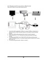
1
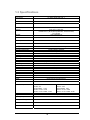
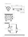
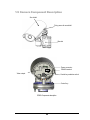
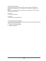
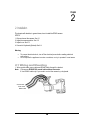
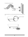
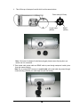
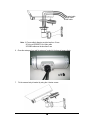
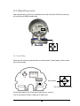
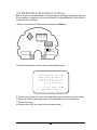
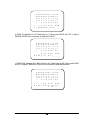
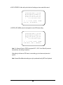
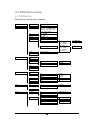
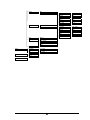
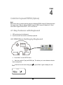
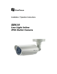
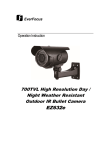
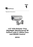
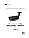
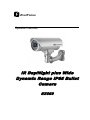
EverFocus Operation Instruction IR Day/Night plus Wide Dynamic Range IP66 Bullet Camera EZ650 EVERFOCUS ELECTRONICS CORPORATION P/N: 4605XZ0650001AR Operation Instruction 2008 EverFocus Electronics Corp Please read this manual first for correct installation and operation. This manual should be retained for future reference. The information in this manual was current when published. The manufacturer reserves the right to revise and improve its products. All specifications are therefore subject to change without notice. All rights reserved. No part of the contents of this manual may be reproduced or transmitted in any form or by any means without written permission of the EverFocus Electronics Corporation. 2 Precautions 1. Do not place any object on top of the cover. 2. Be careful when handling the camera, do not drop it or subject it to strong shock or vibration to prevent any damages to it. Do not disassemble it or place it on an unstable base. 3. Install the camera away from TV, radio transmitter, magnet, electric motor, transformer, audio speakers because the magnetic fields generate from above devices will distort the video image. 4. Install the camera away from stoves, or other heat generating devices as the high temperature could cause deformation, discoloration or other damages of the camera. Install the camera at where the temperature range will stay between -40°C to 50°C (-40°F to 122°F). 5. Never aim the camera at the sun or other extremely bright objects whether it is in use or not. 6. Do not touch the surface of CCD sensor by hand directly. Use a soft cloth to remove the dirt from the camera body. Use lens tissue or a cotton tipped applicator and ethanol to clean the CCD sensor and the camera lens. When the camera is not in use, put the cover cap on the lens mount. 7. All warnings on the products and in the operating instructions should be adhered to. 8. Do not use attachments not recommended by the appliance manufacturer as they may cause hazards. 9. Do not allow anything to rest on the power cord. Do not locate this appliance where the cord will be abused by persons walking on it. 10. Do not overload wall outlets and extension cords as this can result in fire or electric shock. 11. Never push objects of any kind into his appliance through cabinet slots as they may touch dangerous voltage points or short out parts that could result in fire or electric shock. 12. Refer all work related to the installation of this product to qualified service personnel or system installers. 3 Federal Communication Commission Interference Statement This equipment has been tested and found to comply with the limits for a Class B digital device, pursuant to Part 15 of the FCC Rules. These limits are designed to provide reasonable protection against harmful interference in a residential installation. This equipment generates, uses and can radiate radio frequency energy and, if not installed and used in accordance with the instructions, may cause harmful interference to radio communications. However, there is no guarantee that interference will not occur in a particular installation. If this equipment does cause harmful interference to radio or television reception, which can be determined by turning the equipment off and on, the user is encouraged to try to correct the interference by one of the following measures: Reorient or relocate the receiving antenna. Increase the separation between the equipment and receiver. Connect the equipment into an outlet on a circuit different from that to which the receiver is connected. Consult the dealer or an experienced radio/TV technician for help. FCC Caution: Any changes or modifications not expressly approved by the party responsible for compliance could void the user's authority to operate this equipment. This device complies with Part 15 of the FCC Rules. Operation is subject to the following two conditions: (1) This device may not cause harmful interference, and (2) this device must accept any interference received, including interference that may cause undesired operation. 4 Table of Contents 1.1 FEATURES.......................................................................................................................................... 6 1.2 ACCESSORY PARTS LIST .............................................................................................................. 7 1.3 SPECIFICATIONS ............................................................................................................................. 8 1.4 DIMENSIONS ..................................................................................................................................... 9 1.5 CAMERA COMPONENT DESCRIPTION ................................................................................... 11 1.6 BACK PANEL LAYOUT ................................................................................................................. 12 1.7 RELATED PRODUCTS................................................................................................................... 13 2.1 WIRING AND MOUNTING............................................................................................................ 13 2.2 ADJUSTING CAMERA POSITION............................................................................................... 18 2.3 ADJUSTING LENS........................................................................................................................... 19 2.3.1 LENS SETTING ................................................................................................................................ 19 2.4 KEYBOARD CONNECTION (OPTIONAL)................................................................................. 20 3.1 CONTROL KEY GENERAL OPERATION GUIDE.................................................................... 21 3.2 RS485 ID & BAUD RATE SETTING ............................................................................................. 23 3.3 OSD MENU SETUP.......................................................................................................................... 26 3.3.1 OSD Menu Tree.......................................................................................................................... 26 3.3.2 LENS .......................................................................................................................................... 28 3.3.3 EXPOSURE................................................................................................................................ 28 3.3.3.1 SHUTTER............................................................................................................................................. 28 3.3.3.2 AGC (Auto Gain Control – basic low light signal amplification) ........................................................ 28 3.3.3.3 SENS-UP .............................................................................................................................................. 28 3.3.3.4 BLC-Backlight Compensation .............................................................................................................. 29 3.3.3.5 D-WDR................................................................................................................................................. 30 3.3.4 WHITE BALANCE CONTROL .................................................................................................. 31 3.3.5 DAY NIGHT ............................................................................................................................... 31 3.3.6 3DNR......................................................................................................................................... 32 3.3.7 SPECIAL .................................................................................................................................... 32 3.3.7.1 CAM TITLE ......................................................................................................................................... 32 3.3.7.2 D-EFFECT............................................................................................................................................ 33 3.3.7.3 FREEZE................................................................................................................................................ 33 3.3.7.4 MIRROR............................................................................................................................................... 33 3.3.7.5 D-ZOOM .............................................................................................................................................. 34 3.3.7.6 GAMMA............................................................................................................................................... 34 3.3.7.7 NEG. IMAGE ....................................................................................................................................... 34 3.3.7.8 RETURN .............................................................................................................................................. 34 3.3.7.9 MOTION .............................................................................................................................................. 34 3.3.7.10 PRIVACY ........................................................................................................................................... 35 3.3.7.11 SYNC.................................................................................................................................................. 35 3.3.7.12 LANGUAGE ...................................................................................................................................... 35 3.3.7.13 RETURN............................................................................................................................................. 35 3.3.8 ADJUST ..................................................................................................................................... 35 3.3.8.1 SHARPNESS........................................................................................................................................ 36 3.3.8.2 BLUE .................................................................................................................................................... 36 3.3.8.3 RED ...................................................................................................................................................... 36 3.3.9 RESET ........................................................................................................................................ 36 3.3.9.1 FACTORY RESET............................................................................................................................... 36 3.3.9.2 EXIT ..................................................................................................................................................... 36 4.1 KEY FEATURES WITH KEYBOARD .......................................................................................... 37 4.2 OSD MENU SETTING BY KEYBOARD....................................................................................... 37 4.3 LENS ADJUSTMENT BY KEYBOARD........................................................................................ 38 5 Chapter 1 1. Product Overview Achieve long range surveillance with clarity in virtually any lighting conditions. The amazing low light sensitivity of 0.05 lux before the added benefits of advanced DSP technology, delivered by a 1/3” Sony Super HAD CCD II sensor, is just the beginning with the new EverFocus EZ650. A 6-50mm varifocal auto-iris lens combined with high output IR illuminators delivers a useful range of over 80m/261ft.Mount the optional EIR100 auxiliary illuminator and increase the range to over 100m/328ft.Add to that variable output IR control to manage illumination and conserve energy, split glass to prevent internal IR reflection, 560TVL resolution, full motion true day/night images without ghosting even with no ambient light (spec value to .0002 lux; recommended nominal setting for sensup function without ghosting is ~8X), plus Digital Wide Dynamic Range to handle the most challenging of bright or unbalanced scene lighting conditions. All wires are run within the mounting bracket for vandal resistance; the weatherproof bushing between the camera body and mount allows easy installation - no additional waterproof connection box required. Plus, our patent-pending back cover design offers easy access to the cable connections and menu controls. long range, high sensitivity 0 lux performance without ghosting, vandal resistant, IP66, with motorized 6-50mm varifocal auto iris lens, and a full suite of OSD Menu and DSP functions controllable at the camera or remotely via RS485 (3D-DNR to save DVR HDD space, privacy masking, 32X digital zoom, mirroring and rotation, and much more) this is the camera you have been waiting for, and might be the only long range camera you’ll ever need. 1.1 Features 1/3” Sony Super HAD CCD II sensor at .05 lux has 5X better native light sensitivity before DSP low light boost. Starlight super high sensitivity of 0.0002 Lux/F=1.2 is achieved through a sensitivity increase setting of up to 256x. True Day/Night with ICR module Extended IR range of up to 80m/261ft with 42 LEDs and variable output IR control to manage illumination and conserve energy. Optional EIR100 bolt-on illuminator extends range to over 100m/328ft 6~50mm motorized varifocal auto iris lens for long range coverage with clarity Split glass to prevent internal IR reflection. Full motion true day/night images even with no ambient light (0 lux.) Digital Wide Dynamic Range expansion to deliver properly exposed images despite bright light sources, deep shadows and/or unbalanced lighting in the same scene. Provides 3D-Dynamic Noise Reduction to improve picture clarity while enabling DVRs to improve disk storage utilization. Easy to use OSD setup menu with local controls or RS-485 remote control (DVR or keyboard). 6 Motion detection for 4 configurable zones. Privacy mask function for 8 configurable zones. Provides digital zoom up to 32x. Cables routed through weatherproof bushing in the bracket to prevent vandalism or other damage. IP66 weather resistant. Operating temperature range -40°C to 50°C/ -40°F to 122°F, with thermostatically controlled heater Vandal resistant. 1.2 Accessory Parts List Please be careful when you unpack the box due to the electronics devices inside. Check and make sure that you have all the items listed below inside the original box: Camera Unit x 1 Waterproof conduit x 1 (connected to the camera bottom) Bracket x 1 Operation Manual x 1 Mounting kit includes: -Long Screws x 4 (for mounting bracket) -Short Screws x 4 (for connecting camera body to bracket) -Expanding Screws x 4 -Hex key x 1 (for adjusting bracket) -Hexagon wrench x 1 (for adjusting sunshield) Please Note: If an item appears to have been damaged in shipment, replace it properly in its carton and notify the shipper. If any items are missing, notify your EverFocus Electronics Corp. Sales Representative or Customer Service. The shipping carton is the safest container in which the unit may be transported. Save it for possible future use. 7 1.3 Specifications Product Model Pickup Device EZ650 1/3” SONY Super HAD CCD Ⅱ Video Format NTSC or PAL Picture Elements 768 x 494 (NTSC)/752 x 582 (PAL) Horizontal Resolution Sensitivity S/N Ratio Electronic Shutter 560 TV Lines 0.05Lux/F=1.2(AGC ON); 0.0002Lux/F=1.2 (IR off ,Sens-up 256x Max; ~8X recommened) 0 Lux (IR On) Over 52dB (AGC off) 256x, 128x, ….1/50 (1/60) ~1/100,000 Video Output BNC 1.0V p-p 75Ω, Gamma Correction Lens Type True Day & Night Back Light Compensation Auto Gain Control White Balance Sync. Mode Day & Night OSD menu IR Emitters IR Configuration IR wavelength IR LED Lifespan IR Distance 3D-DNR Digital WDR Mirror Digital Zoom Motion Detection Privacy Mask RS-485 Power Source Power Consumption Dimensions Weight Operating Temperature 0.45 DC Iris Varifocal : 6~50mm focal length Yes, automatic motorized IR cut filter OFF/BLC/HSBLC Selectable Low/Middle/High Selectable ATW/AWB/AWC/Manual/Indoor/Outdoor Selectable Internal/Line lock Auto/Color/BW/EXT Multiple functions 42 long life LEDs Split glass isolation prevents internal reflections 850nm 20,000 hours 80m/261ft(AGC ON) ,100m/328ft OFF/ON, adjustable level. Outdoor, Indoor Off/Mirror/V-Flip/Rotate Selectable Off/On selectable up to 32X Off/On for 4 selectable zones Off/On for 8 selectable zones Control input for menu/zoom/focus. 2 models: 24VAC ; 100VAC~240VAC AC24V: AC110~240V: camera: 5W camera: 3.2W camera+heater: 11.5W camera+heater: 9.2W camera + int. IR: 12.7W camera + int. IR: 10.6W camera + int. IR + heater: 19.3W camera + int. IR + heater: 16.6W 115mm x 275mm / 4.5” x 10.8” 2.91kg -40°C to +50°C / -40ºF to 122 ºF Weatherproof Ratings Heater IP66 Yes, Built-in, thermostatically controlled Vandal resistant Yes 8 1.4 Dimensions Drilling Dimension of holes to holes 45mm/1.8” 80mm/3.2” Dimension of Bracket 220.5mm/8.68” 84mm/3.31” 106.5mm/4.19 112.7mm/4.44 199mm/7.83” 9 Dimension of whole camera with bracket 275mm/10.8” 107.5mm/4.3” 243.5mm/9.74” 357mm/14” Dimension of whole camera with bracket and EPR100 10 1.5 Camera Component Description Sun shield Fixing screw for sunshield Bracket Power connector RS485 terminal Video output Control key selection switch Control key EZ650 Component description 11 1.6 Back Panel Layout 24VAC model (for 24VAC Power Only) 2 110V~240VAC model (for 110V ~240V Power only) 2 1 1 3 4 3 5 5 6 6 7 7 1. Video Output Connector Connect the video output of the camera to a color monitor or other video devices through a 75 Ohm type coaxial cable with BNC female connector at backside of the camera. 2. Power Input Terminal Connect the appropriate power to each model. N/L is used to connect to power in. PE is a ground pin. 3. RS-485 communication and External IR power control pin 485- 485+ GND 12VDC PIN definition: a. TXD (RS485 +): for keyboard controlling. b. RXD (RS485-): for keyboard controlling. 4. Power for IR illuminator Referring to above figure, pin 12VDC and GND are defined as below: a. GND: Ground b. 12VDC: provide power source for IR illuminator (IR illuminator is optional). 12 4 5. Control key selection switch Switch to OSD to control OSD menu by using the control key or switch to LENS to adjust zooming and focus (please see “2.3.1 Lens setting” and “3. OSD Menu & Configuration” for details). Note: when it is connected to RS485 for keyboard control, please switch to OSD, otherwise it cannot be controlled remotely. 6. Control key For setting Lens & OSD menu. 7. Cable clips Used to fix power cable and RS485 cable. 1.7 Related Products In addition, you may order the following EverFocus products which are recommended for use with the camera to achieve the best performance: EverFocus control keyboard (EKB500) IR Illuminator and bracket 13 Chapter 2 2. Installation This chapter will describe, in general terms, how to install the EZ650 camera. STEPS: 1. Wire and mount the camera. See 2.1 2. Adjust the camera position. See 2.2 3. Adjust Lens. See 2.3 4. Connect to Keyboard (Optional) See 2.4 Warning To prevent electrical shock, turn off the electrical power before making electrical connections. Do not expose the appliance to water or moisture, nor try to operate it in wet areas. 2.1 Wiring and Mounting 1. Wire coaxial cable, power cable and RS485 cable through the bracket. Note: 1. Please use RG59/5C2V coaxial cable without connector 2. Use RS485 cable only if you need to control the camera by a keyboard. Coaxial cable Power cable RS485 cable 13 2. Fix the bracket to wall by using 4 screws. Coaxial cable Power cable RS485 cable 3. Open camera’s back cover: Loose the 2 screws from the back panel cover, then open the back cover. Screws for back panel 14 4. Take off the cap of waterproof conduit which is at the camera bottom. Power cable (Φ10.3mm) Coaxial cable (Φ6mm) RS485 (Φ5mm) Note: 1. the holes of waterproof conduit were plugged, please remove the plug when you need to use it for connection. 5. Take coaxial cable, power cable and RS485 cable to pass through waterproof conduit, place them into camera housing. Note: Do not connect BNC connector to coaxial cable until coaxial cable has passed through camera housing otherwise your cable might not pass the housing. 15 Coaxial cable Power cable RS485 cable Note: 1. Power cable’s diameter must be less than 10 mm 2. Only use RG59/5C2V for Video cable 3. RS485 cable must be less then 5 mm 6. Close the waterproof cap and fix waterproof conduit to the base of camera firmly. 7. Fix the camera body to bracket by using the 4 shorter screws. 16 8. Connect RG59 coaxial cable with BNC connector. 9. Unscrew both cable clips, wire power cable and RS485 cable through the cable clips. Then, screw the cable clips to rear panel. a. Connecting Power-24VAC model: connect 24VAC power on N and L 100VAC~240VAC Model: Connect PE, N and L. *Warning* To prevent electrical shock, turn off the electrical power before making electrical connections. Do not connect high voltage power to the camera. It may damage the camera. Do not short circuit the power leads and expose the wire when connecting the power supply to the camera. b. Connect Video- Make sure connecter is firmly connected. c. Connecting RS485 (optional): Connect RS585 cable to 485+ and 485-. Please use screw driver to lose and tight the screw on the RS485 terminal pin when you do connection. Power cable RS485 cable Coaxial cable Cable Clips Cable Clips 10. Close the back cover and screw the 2 screws firmly. Now, you are done with the installation. NOTE: Before you close the cover, please make sure control key is attached firmly and wire doesn’t stuck. 17 Screws for back panel 2.2 Adjusting Camera Position Adjust camera’s angle vertically or horizontally by using hex key included in package. Loose this screw to make angle adjustment vertically Loose this screw to make angle adjustment horizontally 18 2.3 Adjusting Lens Open camera’s base, a control key is attached at inner side of the base. Detach the control key and use this key for OSD or Lens setting. UP 2.3.1 Lens Setting Please turn the control key selection switch at the back panel to “Lens”.( key to do lens setting. ). Use the control UP Mini-Joystick The Cursors & the mini-joystick Turn the mini-joystick Up () or Down () to adjust zoom in / zoom out, Turn the mini-joystick Left () or Right () to adjust focus. 19 2.4 Keyboard Connection (Optional) Please refer to Chapter 4 for more details of Keyboard control. 1. 2. 3. 4. 5. Connect the cable from keyboard’s RS485 port to camera’s RS485 port. (Keyboard is an optional accessory). RS485 connecting accessories are included in Everfocus Keyboard package. Connect the cable from video output jack of the camera to monitor’s input jack. EZ650 recognizes EVF-1, EVF-2 and Pelco-D protocols automatically. (No setting is required) The camera default RS485_ID is 01. BAUD_RATE is 9600. Make sure the key board camera ID and Baud rate match. For optional changing camera ID and baud rate on camera, please refer to 3.2. For keyboard setting and operation, please see chapter 4. 20 Chapter 3 3. OSD Menu & Configuration This chapter introduces how to configure the camera OSD menu. 3.1 Control Key General Operation Guide Please turn the control key selection switch at the back panel to “OSD” ”( Use the control key to do OSD menu setting. ). UP Mini-Joystick The Cursors & the mini-joystick I. Bring Up the General OSD Menu Simply press the mini-joystick to bring up the general OSD menu. II. Bring up the RS485 Setting Menu Press the mini-joystick and hold for 5 seconds to bring up the RS485 setting menu. III. Navigate among the OSD Menu Items Turn the mini-joystick up () or down () to move the cursor up or down. IV. Change Modes or Setting Parameters Turn the mini-joystick left () or right () to adjust the mode or parameter of settings. V. Switch to Sub-menu Screens 21 When the item with sub-menu is selected, press the mini-joystick to switch to the sub-menu for further settings. Please refer to the diagram below. SETUP LENS > LENS DC <┘ SHUTTER ___ WHITE BAL. ATW BACKLIGHT OFF AGC MIDDLE DNR LOW Main Menu SENS-UP AUTO <┘ SPECIAL <┘ EXIT NOTE: For those selected items with “ LEVEL |+++++++++| 25 Sub-Menu s Menu ” sign in the end, they have the sub-menu for further settings. VI. Return to Previous Page Press the mini-joystick to return to previous page. VII. Close the Host Menu Screen To close the menu screen, navigate to the “EXIT” item and press the mini-joystick. 22 3.2 RS485 ID & Baud Rate Setting Note: This section is optional preserved for the people that want to change camera ID and baud rate. In most situations, we suggest you can just use Camera ID-01 and Baud Rate-9600, Protocol-Pelco D on keyboard, then it would work. I. Please turn the control key selection switch at back panel to “OSD”( ). II. Press the mini-joystick for 4 seconds until you see the following menu. A N a n ─ F I B O b o · C P c p D Q d q 0 E R e r 1 F S f s 2 G T g t 3 H U h u 4 I V i v 5 J W j w 6 K X k x 7 L Y l y 8 M Z m z 9 C L R P O S E N D R M W A R E _+ V E R _ _ _ III. Turn the mini-joystick up () or down () to adjust setting, press mini-joystick to go next selection. IV. Please wait 3 seconds after setting any item, it will automatically switch to next setting item. V. Camera setting order: a. Firmware version. VER_xxx- shows the current firmware version. 23 A N a n ─ F I B O b o · C P c p D Q d q 0 E R e r 1 F S f s 2 G T g t 3 H U h u 4 I V i v 5 J W j w 6 K X k x 7 L Y l y 8 M Z m z 9 C L R P O S E N D R M W A R E _+ V E R _ _ _ b. RS485_ID- adjustable 01~128. Default value is 01. Move joystick RIGHT and LEFT to adjust it. RS485 ID of EZ650 has to be the same as Keyboard’s CAM ID. A N a n ─ B O b o · C P c p D Q d q 0 E R e r 1 F S f s 2 G T g t 3 H U h u 4 I V i v 5 J W j w 6 K X k x 7 L Y l y 8 M Z m z 9 C L R P O S E N D R S 4 8 5 I D _ 9 9 _ _ _ _ _ c. BAUD_RATE-adjustable 9600, 4800, 2400 and 1200. Default value is 9600. Move joystick RIGHT and LEFT to adjust it. Baud rate of EZ650 has to be the same as Keyboard’s baud rate. A N a n ─ B O b o · C P c p D Q d q 0 E R e r 1 F S f s 2 G T g t 3 H U h u 4 I V i v 5 J W j w 6 K X k x 7 L Y l y 8 M Z m z 9 C L R P O S E N D B A U D _ R A T E _ 9_ 6_ 0_ 0_ _ 0 99 24 d. DATA STORED- Confirm with you that the last 3 settings you have made will be saved. A N a n ─ B O b o · C P c p D Q d q 0 E R e r 1 F S f s 2 G T g t 3 H U h u 4 I V i v 5 J W j w 6 K X k x 7 L Y l y 8 M Z m z 9 C L R P O S E N D D A T A _ S T O R E D _ _ _ _ e. ENTER_SET_MENU- press the mini-joystick to enter OSD menu setting. A N a n ─ B O b o · C P c p D Q d q 0 E R e r 1 F S f s 2 G T g t 3 H U h u 4 I V i v 5 J W j w 6 K X k x 7 L Y l y 8 M Z m z 9 C L R P O S E N D E N T E R _ S E T _ M E N U _ Note: For Camera Protocol, EZ650 recognizes EVF-1, EVF-2 and Pelco-D protocols automatically. (No setting is required) After setting, it will show an OSD menu, to save setting, go to exit menu and press minijoystick. Note: Camera ID and Baud rate setting can only be performed locally, NOT from Keyboard. 25 3.3 OSD Menu Setup 3.3.1 OSD Menu Tree Default settings are shown bold or in brackets. Lens — DC — Brightness 0~100 (50) Exposure — Shutter — x256, x128, x64, x32, x16, x8, x4, x2, 1/60(NTSC) / 1/50 (PAL), FLK,1/250, 1/500, 1/1000, 1/2000, 1/5000, 1/10000 — AGC — HIGH ; MIDDLE ; LOW ; OFF — AUTO (x8) ; OFF — SENS-UP — BLC — OFF — BLC — Gain Default, Left/Right, Width, Top/Bottom, Height, Return — Level Default, Left/Right, Width, Top/Bottom, Height, Return — HSBLC — D-WDR — Return White Balance — — — — ATW AWB AWC->SET Manual — Off, Indoor, Outdoor — Red — Blue — Return — 0~100 (25) — 0~100 (35) — Delay — S-Level — D-Level — 0~63 (5) — 0~100 ( 56) — 0~100 ( 6) — Burst — Return — Off, On — Level — Return — 0~100 (30) — Camera Title — ON — OFF — Return — Characters 0....Z — D-Effect — Mirror — H_MIR ; V_MIR ; OFF Gamma Neg_Image — Return — 0.45~1.00 — ON ; OFF — Indoor — Outdoor — Return Day/Night — EXT — Auto — Color — Black/White — Return 3DNR — ON — OFF Special 26 — Low, Middle, High — 0~8 (5) — Motion — Privacy — Sync. — Language — Off — On — Off — On — INT / LL — English Trad. Chinese Simp. Chinese Japanese — Return — Return Adjust — Sharpness — Blue — Red Reset — Factory — Return — 0~31 (16) — 0~100 (63) — 0~100 (63) Exit 27 — — — — — — — — — Area Select Area Display Left/Right Width Top/Bottom Height Sensitivity Motion View Return — — — — — — — — Area1-Area4 Off, On 5~66 0~93 1~60 0~60 0~40 Off, On — — — — — — — — Area Select Area Display Left/Right Width Top/Bottom Height Color Return — — — — — — — Area1-Area4 Off, On 6~98 0~93 0~60 0~61 0~15 3.3.2 LENS When the SETUP menu is displayed on the screen, please direct the arrow to point to “LENS” by using the UP and DOWN buttons. The iris opening can be adjusted in DC mode in LENS LEVEL. The level can be adjusted from 0 to 50. Please select RETURN and press the SETUP button if you would like to return to the previous menu. 3.3.3 EXPOSURE 3.3.3.1 SHUTTER 1. 2. 3. When the SETUP menu is displayed on the screen, please direct the arrow to point to “EXPOSURE” -> “SHUTTER” by using the UP and DOWN buttons. Select the shutter mode by pressing the LEFT or RIGHT button. Select from x256, x128, x64, x32, x16, x8, x4, x2, 1/60 (1/50 at PAL), FLK, 1/250, 1/500, 1/1000, 1/2000, 1/5000, 1/10000, 1/100000 for NTSC model or x256, x128, x64, x32, x16, x8, x4, x2, 1/50, FLK, 1/250, 1/500, 1/1000, 1/2000, 1/5000, 1/10000, 1/00,000 for PAL model. FLK: Please select “FLK” mode when flickering occurs on the screen, because of an irregular balance between illumination and frequency. NTSC model: 1/100, PAL model: 1/120. Select RETURN and press the SETUP button when you finish all the settings. NOTE: Make sure for default setting 1/60 (NTSC) / 1/50 (PAL), if SENS-UP function is needed in the installation. All other Shutter modes will disable SENS-UP functionality. 3.3.3.2 AGC (AUTO GAIN CONTROL – BASIC LOW LIGHT SIGNAL AMPLIFICATION) Please direct the arrow to point to “AGC” by using the UP and DOWN buttons. Select the level you would like to choose by pressing the LEFT or RIGHT button. The more the level of gain increases, the brighter the screen, but the level of noise increases as well. Please select from HIGH, MIDDLE, LOW and OFF. Note: AGC must be on for sense-up low light boost to function. 3.3.3.3 SENS-UP SENS-UP is used to keep a brilliant, vivid screen image under low light level conditions by automatically compensating for changes in the level of light. Please direct the arrow to point to “SENSE-UP” by using the UP and DOWN buttons. Select the mode you would like to operate by pressing the LEFT or RIGHT button. AUTO: Low light level auto mode. Press SET for adjusting the maximum number of interpolated images. (Default is Auto, 8X) OFF: The function is disabled. Press select RETURN and the SETUP button when you finish all the settings. 28 NOTE: 1. SENS-UP will be disabled, if AGC is OFF or the default SHUTTER value (1/50 PAL / 1/60 NTSC) was changed 2. The image becomes brighter when the setting increases; however, the after image increases as well. Due to the increased light sensitivity of the Super HAD II chip, far less DSP ‘boost’ is needed, resulting in color or B/W images in low light with minimal ghosting. 3. Please note that spots and noise may appear if light amplification increases when SENSE-UP is operating. This is a normal phenomenon, controllable with DNR. 3.3.3.4 BLC-BACKLIGHT COMPENSATION There are three choices for the type of BLC which may be employed: OFF, traditional BLC or HSBLC. BLC Video gain can be adjusted automatically to correct the exposure of subjects that are in front of a bright light source. Please direct the arrow to point to “BLC” by using the UP and DOWN buttons. Select the BLC mode by pressing the LEFT or RIGHT button. Then make adjustments as below: GAIN Select from High, Middle and Low. DEFAULT Set the factory default values for BLC. LEFT/RIGHT Set the Left/Right side of an area for the BLC to be adjusted. The value adjustable is 0~6. WIDTH Set the width of an area for the BLC to be adjusted. The value adjustable is 0~6. TOP/BOTTOM Set the Top/Bottom side of an area for the BLC to be adjusted. The value adjustable is 0~6. HEIGHT Set the height of an area for the BLC to be adjusted. The value adjustable is 0~6. RETURN Press “RET” to save all settings in the BLC menu and return to the previous menu. Press “END” to save all the menu settings and exit. HSBLC HSBLC (Highlight Suppression BLC) is used to reduce the brightness of light sources in a specific area. It is activated only in a low illumination environment to minimize the effects of glare from bright lights such as spotlights, street lights or headlights in the field of view. Where ‘traditional’ BLC can increase the exposure of a dark area surrounded by a brighter area, HSBLC can decrease the exposure of bright areas surrounded by darker areas. 29 1. Please direct the arrow to point to “BLC” by using the UP and DOWN buttons. 2. Select the HSBLC mode by pressing the LEFT or RIGHT button. Then make adjustments as below: LEVEL Adjust the sensitivity level for HSBLC from 0 to 8. DEFAULT Set the factory default values for HSBLC. LEFT/RIGHT Set the Left/Right side of an area for the HSBLC to be adjusted. The value adjustable is 0~6. WIDTH Set the width of an area for the HSBLC to be adjusted. The value adjustable is 0~6. TOP/BOTTOM Set the Top/Bottom side of an area for the HSBLC to be adjusted. The value adjustable is 0~6. HEIGHT Set the height of an area for the HSBLC to be adjusted. The value adjustable is 0~6. RETURN Press “RET” to save all settings in the HSBLC menu and return to the previous menu. Press “END” to save all the menu settings and exit. 3.3.3.5 D-WDR When there are both bright and dark areas in the field of view at same time, this function can help to even the exposure between these areas. 1. Please direct the arrow to point to “D-WDR” by using the UP and DOWN buttons. 2. Select the mode you would like to operate by moving the joystick LEFT or RIGHT. OFF Disables D-WDR function (default) INDOOR Select this option if you are in an indoor environment. OUTDOOR Select this option if you are in an outdoor environment. RETURN Press “RET” to save all settings in the Exposure menu and return to the previous menu. Press “END” to save all the menu settings and exit. 30 3.3.4 WHITE BALANCE CONTROL The screen color can be adjusted by using the WHITE BALANCE function. Please direct the arrow to point to “WHITE BAL” by using the UP and DOWN buttons. Please select the mode you would like to operate by pressing the LEFT or RIGHT button. Please select one of the 6 modes below: ATW Auto Tracking White Balance: This mode can be used within the color temperature range from 5,500°K to 6,000°K (eg, fluorescent light, outdoor, sodium vapor lamp or inside tunnels). AWB Auto White Balance: This mode can be used within the color temperature range from 2,500°K to 10,000°K. (default) AWC ->SET To find the optimal setting for the current luminance environment in this mode, point the camera toward a sheet of white paper, and press “SET”. If the environment changes, you will have to readjust it. MANUAL The manual adjustment mode enables a more precise adjustment. Please select ATW or AWC first. Then change to manual adjustment mode and press the SETUP button. Set the suitable color temperature, and increase or decrease the red and blue color values at the same time while checking the color changes of the objects in view. Press “RET” to save all settings in this menu and return to the previous menu. Press “END” to save all the menu settings and exit. INDOOR Select this option when the color temperature is 5,600°K. OUTDOOR Select this option when the color temperature is 3,300°K Press “RET” to saves all settings in this menu and returns to the previous menu. Press “END” to save all the menu settings and exit. 3.3.5 DAY NIGHT These settings control the operation of the camera when the illumination level changes. Choices are Color at all times; B/W at all times; or color when illumination is bright, switching to B/W in low light. PLEASE NOTE: In “color” operation, there is an IR “cut” (blocking) filter between the lens and the sensor; the EZ650 has very little IR sensitivity when the image is displayed in color. The EZ650 camera will have excellent IR sensitivity when displaying a low light B/W picture. To properly utilize the IR illuminators on the EZ650 in low light situations, it is essential to select either the AUTO or the B/W operating mode in this menu. B/W BURST The picture is always displayed in B/W. OFF/ON: ON: Retains the color burst information; minor color noise may appear when ambient illumination is low. OFF: With color burst signal off, picture will be pure B/W. 31 Press “RET” to save all settings in the DAY/NIGHT menu and returns to the previous menu. Press “END” to save all the setting menus and exit. COLOR AUTO Delay S-Level E-Level EXT The picture is always displayed in color, even at low light levels. NOTE: In “color” operation, there is an IR “cut” (blocking) filter between the lens and the sensor; thus EZ650 camera has very little IR sensitivity when the image is displayed in color. The picture switches to color in a normal (bright) environment and switches to B/W when the ambient illumination is low. The switching point is controlled by the video signal level. Note: AGC selection must be set as middle or high in order to employ the auto switching function. Delay time for switch reaction on light changes, range 0~63 seconds. Trigger level for switching to day mode in range 0~100. Trigger level for switching to night mode in range 0~100. NOTE: The AUTO mode is not recommended for applications with highpower IR illumination. The camera may switch continuously between Day and Night mode. The picture will switch automatically to color in a normal environment and to B/W when the ambient illumination is low based on the illumination reaching the light sensor at the front of the camera body. 3.3.6 3DNR 3DNR reduces the background noise in a low luminance environment. OFF Disables 3DNR to keep the same amount of noise. ON Enables 3DNR to reduce the noise. (default) Level Noise reduction level from 0~100 while observing a low light image until the desired image is achieved. (default=30) Press “RET” to saves all settings in DNR menu and returns to the previous menu. Press “END” to save all the setting menus and exit. 3.3.7 SPECIAL In this section, user can do special settings including camera title, digital effects, motion, privacy zones, synchronization and language. Please direct the arrow to point to “SPECIAL” on the SETUP menu by using the UP and DOWN buttons. Select the mode you would like to operate by pressing the LEFT or RIGHT button. 3.3.7.1 CAM TITLE Input the camera title, and it will be appeared on the monitor. 32 Please direct the arrow to point to “CAM TITLE” by using the UP or DOWN button. Select “ON” by pressing the LEFT or RIGHT button. Press SETUP button. Maximum 15 characters can be used for the ID. Use UP, DOWN, LEFT and RIGHT buttons to move the cursor to the letter to be chosen. Use SETUP button to choose that letter. Once a name has been selected, please choose the position on the screen where you would like to display the name. Move the cursor onto “POS” and press the SETUP button. The name will appear at the top left hand corner. Please use the 4 directional buttons to move the position of the displayed name. Press the SETUP button when the desired location has been reached. If you would like to cancel the ID entered, please move the cursor to “CLR”, and all the letters entered will be deleted. Select “END” and press the SETUP button to complete ID input. 3.3.7.2 D-EFFECT Offers a number of digital functions for processing the image. 3.3.7.3 FREEZE OFF ON Select “OFF” to view live image. Select “ON” to freeze and display current live image. 3.3.7.4 MIRROR OFF MIRROR V-FLIP ROTATE Disable digital effects. The image is displayed horizontal flipped. The image is displayed vertical flipped. Rotate the image 180˚. 33 3.3.7.5 D-ZOOM Setup for digital zoom. OFF ON Disable the D-ZOOM function D-Zoom: Select digital zoom from X1.0 up to X32. Note that zoom levels above X4 may lead to excessive pixellation. Setup of the position of the magnified image in view (0 is the center of the image): Pan: Select digital pan from -100 to 100. Tilt: Select digital tilt from -100 to 100. Press “RET” to saves all settings in D-ZOOM menu and returns to the previous menu. Press “END” to save all the setting menus and exit. 3.3.7.6 GAMMA This menu allows adjustment of gamma correction for ideal linearity of image brightness and contrast in the range 0.05 to 1.0. 3.3.7.7 NEG. IMAGE Allows user to create a negative of the original image. A negative image is a tonal inversion of a positive image, in which light areas appear dark and vice versa. A negative color image is additionally color reversed, with red areas appearing cyan, greens appearing magenta and blues appearing yellow. 3.3.7.8 RETURN Return: Press “RET” to save all settings in D-EFFECT menu and return to the previous menu. Press “END” to save all the menu settings and exit. 3.3.7.9 MOTION This camera enables you to observe movements of objects in 4 different areas on the screen, and the message “MOTION DETECTED” appears on the screen when movement is detected. The camera detects an object’s movement by sensing changes in the pixels displayed. OFF ON AREA SELECT AREA DISPLAY LEFT/RIGHT WIDTH TOP/BOTTOM HEIGHT SENSITIVITY Disables the MOTION function. Please select the area you would like to detect from the 4 areas in AREA SELECT mode Select “ON” to use the motion area selected in sensitivity. Select “OFF” to disable this function. Set the coordinate of the horizontal axis 5~66. Set the size of horizontal area 0~93. Set the coordinate of the vertical axis 1~60. Set the size of vertical area 0~60. Set the sensitivity level for the motion trigger by selecting from 0~40. When 34 MOTION VIEW RETURN the sensitivity value is high, motion detection sensitivity increases to sense very small movements and vice versa. Select “ON” to display motion detection pixels in the live view. Press “RET” to save all settings in MOTION menu and return to the previous menu. Press “END” to save all the menu settings and exit. 3.3.7.10 PRIVACY This mode masks areas you do not want to display on the screen or record. OFF ON AREA SELECT AREA DISPLAY LEFT/RIGHT WIDTH TOP/BOTTOM HEIGHT COLOR RETURN Disable the PRIVACY function. Please select the area you would like to hide from the 8 areas in AREA SELECT mode. Select “ON” to use the area selected in the AREA SELECT. Select “OFF” to disable this function. Set the coordinate of the horizontal axis 6~98. Set the size of horizontal area 0~93. Set the coordinate of the vertical axis 0~60. Set the size of vertical area 0~61. Set area color. It is selectable from 0 to 15. Press “RET” to save all settings in PRIVACY menu and return to the previous menu. Press “END” to save all the menu settings and exit. 3.3.7.11 SYNC There are two SYNCHRONIZATION modes INTERNAL and LINE-LOCK. In LINE-LOCK mode, the video signal is synchronized to the frequency of the incoming AC power. The Line-Lock synchronization can only be used when the supply power is 24VAC 60Hz (NTSC models) or 50Hz (PAL models). INT L/L Internal synchronization Line-lock synchronization (only for 24 VAC) 3.3.7.12 LANGUAGE Select OSD language. EZ650 camera supports multiple languages including English, Japanese, Traditional Chinese and Simplified Chinese. 3.3.7.13 RETURN Press “RET” to save all settings in the SPECIAL menu and return to the previous menu. Press “END” to save all the menu settings and exit. 3.3.8 ADJUST Adjust sharpness, Blue and Red level in this section. 35 3.3.8.1 SHARPNESS The contour of the video image becomes cleaner and more easily distinguished as the level of SHARPNESS increases. If the level is set too high, it may affect the video image and cause noise. The available range of level is 0~31. 3.3.8.2 BLUE Adjust image’s blue level. The available range of level is 0~100. 3.3.8.3 RED Adjust image’s red level. The available range of level is 0~100. Press “RET” to saves all settings in the ADJUST menu and returns to the previous menu. Press “END” to save all the menu settings and exit. 3.3.9 RESET 3.3.9.1 FACTORY RESET Reset to the factory default settings. Press “RET” to return to the previous menu. Press “END” to exit. 3.3.9.2 EXIT Save all the menu settings and exit. NOTE: If you quit a Menu without pressing EXIT, all the settings you previously modified will NOT be saved. 36 Chapter 4 Control from Keyboard EKB500 (Optional) Note! Before being able to control keyboard, make sure Keyboard RS485 camera ID, Baud rate match the camera. (see COM port setting in EKB500 manual). EZ650 camera ID default is 01. Baud rate is 9600. Support Protocol EVF-1, EVF-2 and Pelco-D. 4.1 Key Features with Keyboard 1. OSD can be set up from Keyboard. 2. Lens Zoom and Focus can be controlled by keyboard. 4.2 OSD Menu Setting by Keyboard a. Press “Menu” to enter SETUP menu. b. Move the joystick UP () and DOWN (). This allows you to move between selection items in setup menu. c. If the item has sub-menu setting (sign menu. ), press “Menu” again to display the sub- SETUP > LENS SHUTTER WHITE BAL. DC <┘ ___ ATW 37 d. Move the joystick RIGHT () and LEFT () to adjust the mode and parameters of the selected item. e. Press “Menu” to leave and goes to previous menu after setting. Move to “exit” and press “menu” button when you finish all settings. f. For detail setting and every setup function, Please refer to “3.3. OSD Menu Setup”. 4.3 Lens Adjustment by Keyboard 1. Press Zoom in or Zoom out to adjust zoom or Turn Joystick clockwise to zoom out. Counterclockwise to zoom in. 2. Press Focus N or Focus F to adjust focus. 3. Press Iris + and Iris – to adjust Iris. 38 EverFocus Electronics Corp. EverFocus Taiwan: 12F, No.79, Sec. 1, Shin-Tai Wu Road, Hsi-Chih, Taipei, Taiwan TEL: +886 2 2698 2334 FAX: +886 2 2698 2380 www.everfocus.com.tw [email protected] EverFocus Europe - Germany: Albert-Einstein-Strasse 1, D-46446 Emmerich, Germany TEL: +49 2822 93940 FAX: +49 2822 939495 www.everfocus.de [email protected] EverFocus China - Beijing: Room 609, Technology Trade Building, Shangdi Information Industry Base, Haidian District, Beijing 100085, China TEL: +86 10 6297 3336~39 FAX: +86 10 6297 1423 www.everfocus.com.cn [email protected] EverFocus China - Shenzhen: 4F, No. 2, D4 Building, Wan Yelong Industrial Park, Tangtou Road, Shiyan, Baoan, Shenzhen, Guangdong 518101, China TEL: +86 755 2765 1313 FAX: +86 755 2765 0337 www.everfocus.com.cn [email protected] EverFocus USA - California: 1801 Highland Avenue, Unit A, Duarte, CA 91010, USA TEL: +1 626 844 8888 FAX: +1 626 844 8838 www.everfocus.com [email protected] EverFocus USA - New York: 415 Oser Avenue, Unit S, Hauppauge, NY 11788, USA TEL: +1 631 436 5070 FAX: +1 631 436 5027 www.everfocus.com [email protected] EverFocus Japan: 5F, Kinshicho City Building, 2-13-4 KotoBashi,Sumida-Ku, Tokyo, 130-0022, Japan TEL: +81 3 5625 8188 FAX: +81 3 5625 8189 www.everfocus.co.jp [email protected] EverFocus Europe - UK: Unit 12, Spitfire Business Park, Hawker Road, Croydon Surrey, CR0 4WD, UK TEL: +44 (0) 20 8649 9757 / 0845 430 9999 FAX: +44 (0) 20 8649 9907 www.everfocus.com [email protected] EverFocus India: Suite 803, Housefin Bhavan, C-21, Bandra Kurla Complex, Bandra (East), Mumbai 400051, India TEL: +91 22 6128 8700 FAX: +91 22 6128 8705 www.everfocus.in [email protected] Your EverFocus product is designed and manufactured with high quality materials and components which can be recycled and reused. This symbol means that electrical and electronic equipment, at their end-oflife, should be disposed of separately from your household waste. Please, dispose of this equipment at your local community waste collection/recycling centre. In the European Union there are separate collection systems for used electrical and electronic product. Please, help us to conserve the environment we live in! Ihr EverFocus Produkt wurde entwickelt und hergestellt mit qualitativ hochwertigen Materialien und Komponenten, die recycelt und wieder verwendet werden können. Dieses Symbol bedeutet, dass elektrische und elektronische Geräte am Ende ihrer Nutzungsdauer vom Hausmüll getrennt entsorgt werden sollen. Bitte entsorgen Sie dieses Gerät bei Ihrer örtlichen kommunalen Sammelstelle oder im Recycling Centre. Helfen Sie uns bitte, die Umwelt zu erhalten, in der wir leben! 39