1
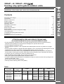
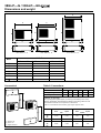
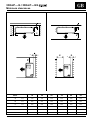
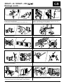
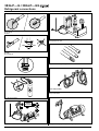
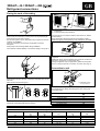
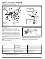
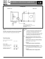
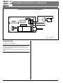
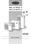
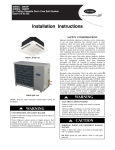
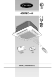
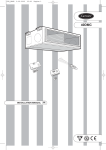
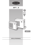
38GLP---G/38GLP---G9
INSTALLATION MANUAL
For operation and maintenance instructions of this unit as well as installation
instructions of the indoor unit, refer to the relevant manuals
Contents
Dimensions and weight .................................................................................................................
Connections ..................................................................................................................................
Minimum clearances .....................................................................................................................
System charge ...............................................................................................................................
General information .......................................................................................................................
Warnings: avoid .............................................................................................................................
Refrigerant connections ................................................................................................................
Operating limits .............................................................................................................................
Electrical connections ...................................................................................................................
Electrical data ................................................................................................................................
Pump down and check the refrigerant charge ..............................................................................
Unit maintenance ..........................................................................................................................
Troubleshooting and guide for the owner .....................................................................................
Accessories ...................................................................................................................................
Installation instructions supplement .............................................................................................
Page
2
2
3
3
4
5
6/8
8
9/10
10
11
12
12
12
13/14
ENGLISH
38GLP---G / 38GLP---G9
Cooling only split system outdoor units
ATTENTION INSTALLERS AND SERVICE TECHNICIANS!
AIR CONDITIONER WITH R-410A–QUICK REFERENCE GUIDE
• R-410A refrigerant operates at 50%-70% higher pressures than R-22. Be sure that servicing
equipment and replacement components are designed to operate with R-410A.
• R-410A refrigerant cylinders are pink.
• R-410A refrigerant cylinders have a dip tube which allows liquid to flow out of cylinder in an upright
position.
• R-410A systems should be charged with liquid refrigerant. Use a commercial type metering device in the
manifold hose in order to vaporize the liquid refrigerant before it enters in the unit.
• The R-410A, as for other HFC, is only compatible with oils chosen by the compressor manufacturer.
For this reason, for the type of oil to be used, always refer to the plate on the compressor and the unit.
• A vacuum pump is not enough to remove moisture from oil.
• POE oils absorb moisture rapidly. Do not expose oil to atmosphere.
• Never open system to atmosphere while it is under vacuum.
• In case the system should be opened for maintenance, stop the vacuum function with dry nitrogen and
replace the drier filters, if any.
• Do not vent R-410A into the atmosphere.
• Use only Carrier matching indoor units (Table I).
Table I
Cooling
only models
Power
supply
38GLP018G
38GLP024G
230V ~ 50Hz
38GLP018G9
38GLP024G9
38GLP028G9
38GLP036G9
38GLP048G9
38GLP060G9
400V 3N ~ 50Hz
Hi-Wall
Cassette
Console
Satellite
42PHQ018N 42PHQ018P 40KMC018
42PHQ024N 42PHQ024P 40KMC024
42VMC018 40SMC018N 40DMC018
42VMC024 40SMC024N 40DMC024
42PHQ018N 42PHQ018P 40KMC018
42PHQ024N 42PHQ024P 40KMC024
40KMC028
40KMC036
40KMC048
40KMC060
42VMC018
42VMC024
42VMC028
42VMC036
42VMC048
40SMC018N
40SMC024N
40SMC028N
40SMC036N
40SMC048N
40SMC060N
40DMC018
40DMC024
40DMC028
40DMC036
40DMC060
GB - 1
38GLP---G / 38GLP---G9
Dimensions and weight
A
A
A
B
B
E
D
E
B
E
E
F C
C
Mod. 38GLP 18 - 24
E
F
D
E
F
C
Mod. 38GLP 28 - 36
Mod. 38GLP 48 - 60
18
24
38GLP
28
36
mm
800
800
800
800
800
800
mm
590
590
803
803
1264
1264
mm
300
300
300
300
300
300
mm
508
508
508
508
508
508
mm
146
146
146
146
146
146
mm
330
330
330
330
330
330
kg
45
51
65
65
92
94
Mod.
A
B
C
D
E
F
D
48
60
Table II: Connections
Connessioni
Model
2
18
24
28
36
48
60
Max. pipe length
30 m
40 m
40 m
50 m
50 m
50 m
Max. height difference
10 m
15 m
25 m
30 m
30 m
30 m
All fittings are flare type.
Use only refrigeration grade pipes, (Cu DHP type according to ISO 1337),
seamless, degreased, deoxidized and suitable for operating pressures of at
least 4200 kPa and with a burst pressure of 20700 kPa.
Under no circumstances must sanitary type copper pipe be used.
3
1
1
Model
Pipe diameter
Liquid
Gas
mm
3
햲 Outdoor unit
햳 Indoor unit
햴 Height difference
GB - 2
2
Pipe diameter
Liquid
Gas
inches
18
24
12.70
6.35
1/2"
1/4"
28
15.87
6.35
5/8"
1/4"
36
48
60
19.05
9.52
3/4"
3/8"
38GLP---G / 38GLP---G9
Minimum clearances
ENGLISH
D
A
C
B
E
E
Mod.
D
18
24
28
36
48
60
A
mm
100
100
100
100
100
100
B
mm
250
250
250
250
250
250
C
mm
500
500
500
500
500
500
D
mm
50
50
100
100
100
100
E
mm
470
470
670
670
670
670
F
mm
400
400
400
400
400
400
GB - 3
38GLP---G / 38GLP---G9
General information
IMPORTANT:
During the unit installation make first refrigerant connections
and then electrical connections.
If unit is uninstalled first disconnect electrical cables, then
refrigerant connections.
WARNING:
Disconnect the mains power supply switch before servicing
the system or handling any internal parts of the unit.
• The manufacturer declines any liability for damage resulting from
modifications or errors in the electrical or refrigerant connections.
• Failure to observe the installation instructions or use of the unit
under conditions other than those indicated in Table III “Operating
limits”, will immediately void the unit warranty.
• Failure to observe electric safety codes may cause a fire hazard in
case of short circuits.
• Inspect equipment for damage due to improper transportation or
handling: file an immediate claim with the shipping company.
Do not install or use damaged units.
• In case of any malfunctioning turn the unit off, disconnect the
mains power supply and contact a qualified service engineer.
• This equipment contains R-410A refrigerant, a substance that is
not depleting the ozone layer.
GB - 4
Choosing the installation site
Positions to avoid:
• Exposed to direct sun.
• Too close to sources of heat radiation, vapour or flammable gas.
• Particularly dusty areas.
Recommendations:
• Choose a position protected from opposing winds.
• Choose a position sheltered from direct sun.
• Choose an area where air outlet and unit noise will not bother
your neighbours.
• Choose a position that allows for the clearances required.
• Floor structure should be adequately strong to support unit weight
and minimize vibration transmission.
• Consider a position which will not obstruct passageways or doors.
508 mm
mm
R-410A systems operate at higher pressures than standard
R-22 systems.
Do not use R-22 service equipment or components on R-410A
equipment.
Read this instruction manual thoroughly before starting the
installation.
• This unit complies with low-voltage (EEC/73/23) and
electro- magnetic compatibility (EEC/89/336) directives.
• For trouble-free installation, it should be carried out by a qualified
installer.
• Follow all current national safety code requirements. In particular
ensure that a properly sized and connected ground wire is in place.
• Check that voltage and frequency of the mains power supply are
those required; the available power must be adequate to operate
any other possible appliances connected to the same line.
Also ensure that national safety code requirements have been
followed for the mains supply circuit.
• The mains supply must be connected to the outdoor unit.
• Connect indoor and outdoor units with field-supplied copper
pipes by means of flare connections.
Use insulated seamless refrigeration grade pipe only, (Cu DHP
type according to ISO1337), degreased and deoxidized,
suitable for operating pressures of at least 4200 kPa and for
burst pressure of at least 20700 kPa.
Under no circumstances must sanitary type copper pipe be
used.
• After installation thoroughly test the system operation and explain
all system functions to the owner.
• Leave this manual with the owner for consultation during future
periodic maintenance.
• Use this unit only for factory approved applications:
the unit is suitable for outdoor installation.
• The outdoor unit and its components must be periodically
inspected to check for loose, damaged or broken parts.
If these faults are found and not eliminated, the unit could cause
physical injury to persons and damage to goods and property.
• This installation manual describes the installation procedures of
the outdoor unit of a residential split system consisting of two units
manufactured by Carrier.
Consult factory or a qualified system engineer prior to connecting
this unit to any other manufacturer's indoor unit.
Coupling units which have different control systems, may cause
irreversible damage and void the warranty protection.
The manufacturer declines any liability for system malfunction
resulting from unapproved coupling.
• All of the manufacturing and packaging materials used for
your new appliance are compatible with the environment and
can be recycled.
• Dispose of the packaging material in accordance with local
requirements.
• This equipment contains refrigerant that must be disposed of
in a proper manner.
When disposing of the unit after its operational life, remove it
carefully.
The unit must then be delivered to an appropriate disposal center
or to the original equipment dealer.
• When lifting the unit, absolutely do not use hooks inserted in the
side handles, use special equipment (e.g. lifting devices, trolleys,
etc...).
• Carefully recover refrigerant within this unit before final
disposal or when servicing.
Never vent refrigerant to atmosphere.
Use approved recovery equipment for R-410A refrigerant.
Do not use R-22 equipment.
330
Unit installation
�
� No. 4 Ø 8 mm pins.
� Protrusion height from the support surface max. 20 mm.
• Fix the unit with locally purchased bolts buried in the block to
prevent overturning due to strong gusts of wind.
Snow
• If the unit is installed in areas where heavy snowfalls may occur, it
is necessary to raise its level at least 200 mm above the usual
snow level or alternatively to use the outdoor unit bracket kit.
38GLP---G / 38GLP---G9
Warnings: avoid....
ENGLISH
Disconnecting the refrigerant connections after installation:
this will cause refrigerant leaks.
Connecting the condensate drain pipe to the outdoor unit.
Excessive height difference between indoor and outdoor unit (see
Table II "Connections"). Excessive distance between indoor and
outdoor units. (see Table II "Connections").
Predominant head winds.
Unnecessary turns and bends in the connecting pipes.
Multiple unit installation with units facing each other.
Any slack in the electrical connections.
Insulating the connecting pipes only partially, which will cause dripping.
Dripping into passageways.
Flattening or kinking of refrigerant or condensate pipes.
Any obstruction of the unit air outlet and intake or any obstacle that is too
close (see minimum clearances required). Installation on grassy ground
or soft surfaces (in these cases a solid foundation must be included).
Soiling of pipe ends.
Allowing piping to get wet before connection.
GB - 5
38GLP---G / 38GLP---G9
Refrigerant connections
No moisture.
No dust.
Charge liquid-no gas.
No leak.
No mineral oil.
Copper tubes during storage.
Neat.
1/2” UNF (R-410A)
Use tools designed for R-410A higher pressure.
Keep inside clean.
Dry nitrogen brazing.
Min.
– 100 kPa
(– 755 mmHg)
Vacuum.
GB - 6
2-stage vacuum pump. Replace oil regularly.
38GLP---G / 38GLP---G9
Refrigerant connections
ENGLISH
Flaring the ends of the tubing
2
1
The unit can be installed:
햲 on the floor;
햳 on the wall using the bracket kit.
Remove protective caps from copper tube ends.
Position tube end downward, cut the tube to the requested length
and remove the burrs with a reamer.
Do not leave system open to atmosphere any longer than minimum
required for installation.
Oil in the compressor is extremely susceptible to moisture
absorption.
Always keep ends of tubing sealed during installation.
The maximum residual quantity of oil used for tubing is 40 mg/10 m.
Connect tubing in accordance with the limits shown on Table II
(Connections).
Finger-tighten the fitting several turns, then tighten it with a
wrench by applying the tightening torque indicated in the table.
Where required, the unit must be charged with additional
refrigerant.
Additional charge must be added using electronic scales and
the service port (5/16") on the suction line.
Charge refrigerant only in liquid phase (bottle turned upside
down or using the specific connection on bottle; see page 1).
Connection to unit
햴
Remove flare nuts from the unit connections and place them on the
tube end.
Flare the tube with the flaring tool.
햴 Adjustable wrench
or torque wrench
L
L
Insufficient tightening torque will cause gas leaks.
Overtightening the fittings will damage the tube flaring and
cause gas leaks.
Pipe diameter
Tightening torque
Nm
18
42
55
65
100
6.35 mm (1/4”)
9.52 mm (3/8”)
12.70 mm (1/2”)
15.87 mm (3/8”)
19.05 mm (1/2”)
Flare end must not have any burrs or imperfections.
The length of the flared walls must be uniform.
Tightening torque
Valve
1/4”
3/8”
1/2”
5/8”
3/4”
Flare nut
Nm
18
42
55
65
100
Valve cap
Nm
20
20
40
40
40
Pressure port cap
Nm
16 - 18
16 - 18
16 - 18
Valve needle
Nm
9
9
13
13
13
Pressure port
Nm
0.34
0.34
0.34
GB - 7
38GLP---G / 38GLP---G9
Refrigerant connections
!
햽
햹
햿
햺
햾
햳
햴
햵
햶
햷
햸
Three-way valve
Needle valve
Valve cap
Valve needle
Two-way valve
Allen (hex. head) wrench
햹
햺
햻
햽
햾
햿
Gas line (large diameter)
Liquid line (small diameter)
Flare nut
Indoor unit
Outdoor unit
Vacuum pump
Air purging
헂
Use only a vacuum pump to purge air from the piping.
NEVER use the system compressor as a vacuum pump.
NEVER use the unit refrigerant gas to purge the connecting
pipes.
No additional refrigerant has been provided in the unit for this
purpose. Remove the caps from the two and three-way valves.
Create a vacuum with a vacuum pump connected to the service
connection of the suction shut-off valve, as shown, keeping the
shut-off valves completely shut until a 50 Pa (0.5 mbar) vacuum
has been reached.
Now open the two-way valve for 3 sec., then quickly shut it to check
for possible leaks.
!
After the leak check, fully open the two and three-way
valves. Do not go beyond the valve stop limit.
Replace caps and check for leaks.
헀
헁
헀 Pipe
헁 Pipe insulation
헂 Fastening tape
Once all connections have been completed, check for leaks by
using a leak detector specific for HFC refrigerants.
Finally wrap the valves and pipes with anti-condensate insulation
and tighten this with tape, without exerting too much pressure on
the insulation.
Repair and cover any possible cracks in the insulation.
Fix the pipes to the wall with hooks or conduits.
Table III: Operating limits (1)
Cooling (2)
outdoor temperature 43°C
Maximum conditions
indoor temperature 32°C d.b.; 23°C w.b.
outdoor temperature-15°C
Minimum conditions
indoor temperature 21°C d.b.; 15°C w.b.
Mains power supply
Nominal single-phase voltage
230V ~ 1pH 50Hz
38GLP---G
Operating voltage limits
min. 198V – max. 264V
Mains power supply
38GLP---G9
Nominal three-phase voltage
Operating voltage limits
400V 3N ~ 50Hz
min. 342V – max. 462V
Notes:
GB - 8
1. Data referred to the outdoor unit only.
2. According to ISO 5151.2/T1.
3. The 38GLP units are fitted with Head Pressure
Controller and can operate at an outside temperature
up to –15°C.
(3)
d.b. - dry bulb w.b. - wet bulb
38GLP---G / 38GLP---G9
Electrical connections
ENGLISH
Single-phase version
Cooling only unit
Cooling only system
L N R C Y
�
L N R C Y O W2 S
230V ~ 50Hz
L N R C Y
햳
햲
10
햲
120
쐋 쐏
R C Y O W2 S
�
10 100
햳
Terminal box legend, all models
L
L1
L2
L3
N
R
C
Y
Earth
Live power supply.
Live power supply.
Live power supply.
Live power supply.
Neutral power supply.
Live connection indoor/outdoor unit.
Neutral connection indoor/outdoor unit.
Compressor interlocking contact.
햲 Mains supply connecting cable
(field wiring).
햳 Connecting cable Outdoor unit – Indoor unit
(R - C - Y - ) - (field wiring).
쐃 Indoor unit
쐇 Outdoor unit
쐋 Main switch
쐏 Time-delay fuse or circuit breaker
(see table IV "Electrical data").
Three-phase version
Cooling only unit
Cooling only system
L1 L2 L3 N R C Y
�
L1 L2 L3 N R C Y
R C Y O W2 S
L1 L2 L3 N R C Y
10
햳
햲
120
10 100
�
햲
햳
�
�
400V 3N ~ 50Hz
GB - 9
38GLP---G / 38GLP---G9
Electrical connections
• For 230 V ~ 1 pH 50 Hz single-phase unit
Before proceeding with the unit connection to the mains supply
locate live L and neutral N, then make connections as shown
in the wiring diagram.
• For 400V 3N ~50 Hz three-phase unit
Before proceeding with the unit connection to the mains supply
locate live L1,L2,L3 and neutral N, then make connections as
shown in the wiring diagram.
When the electric supply cables L1 (R), L2 (S), L3 (T) are
connected inversely, a special “PSC” phase inversion protection
device blocks the compressor to prevent the same from rotating
inversely.
In this case, switch off the electrical supply and check the
correctness of the sequence of the cables of the supply line
connected to the main terminal block (they are probably
inverted).
The compressor will only be allowed to work if the phase
sequence is correct.
The phase sequence protection device also continuously
monitors the electrical supply line and if one of the phases is
completely missing it blocks the compressor.
The device only re-starts the compressor after the supply line is
correctly restored.
All the three phase compressors have identical internal wiring.
For this reason when the correct phase connections for a
specific system have been determined, the rotation direction will
always be correct if the same connections are made to the
terminal block (for the other equipment).
• Make refrigerant connections before electrical
connections. When disconnecting, disconnect electrical
connections before refrigerant connections.
IMPORTANT:
Make ground connection prior to any other electrical
connections.
Note:
All field electrical connections are the responsibility of the
installer.
• According to the installation instructions, the disconnecting
switches from the mains power supply should have a contact gap
(4 mm) such that total disconnection can be ensured under the
conditions provided for by overvoltage class III.
Refer to the indoor unit installation manual for sizing the
connection wires between units.
• Remove electric box cover.
• Make electrical connections between units prior to proceeding
to mains supply unit connection.
• Connect the wires to the terminals according to the wiring
diagram and firmly tighten.
• The mains supply indoor unit – outdoor unit connecting cable
must be H07 RN-F (60245IEC66) type synthetic rubber insulation
with neoprene coating.
Note:
After connections have been completed, replace electric box
cover.
Table IV: Electrical data (1)
Power input
Starting
current
(2)
Main power
connections (6)
Heating
Cooling
Nominal conditions
230V ~ 50Hz
ISO 5151.2/T1
indoor 27°C d.b. 19°C w.b.
outdoor 35°C d.b. 24°C w.b.
(5)
Nominal conditions
Peak conditions
230V ~ 50Hz
198V ~ 50Hz
ISO 5151.2/High+
ISO 5151.2/T1
indoor 32°C d.b. 23°C w.b. indoor 20°C d.b. 15°C w.b.
outdoor 43°C d.b. 32°C w.b. outdoor 7°C d.b. 6°C w.b.
Peak conditions
198V ~ 50Hz
ISO 5151.2/High+
indoor 27°C
outdoor 24°C d.b. 18°C w.b.
Time-delay
fuse
gL type
Wire size
(3-4)
A
A
W
A
W
A
W
A
W
A
mm 2
38GLP018G
38GLP024G
38GLP018G9
40
60
24
9.3
10.1
3.8
2110
2300
1950
13.1
15.1
4.4
2560
3100
2600
-------
-------
-------
-------
20
25
10
2.5
2.5
2.5
38GLP024G9
38GLP028G9
38GLP036G9
32
37
39
4.5
4.8
4.9
2270
2900
3100
5.3
5.5
6.4
3060
3450
3800
-------
-------
-------
-------
10
16
16
2.5
2.5
2.5
38GLP048G9
38GLP060G9
54
60
6.3
6.8
3300
4580
7.5
9.2
3950
5480
-----
-----
-----
-----
16
25
2.5
2.5
Cooling only
Notes:
1.
2.
3.
4.
5.
6.
GB - 10
Unit is suitable for outdoor installation.
Starting current duration is usually lower than 1 sec.
Wire size shown applies to line length up to 15 m.
If the indoor unit is provided with an electric heater, consult indoor unit installation manual for correct sizing of the wires.
Data referred to the outdoor unit only.
The mains supply connecting cable must be H07 RN-F (60245IEC66) type synthetic rubber insulation with neoprene coating.
38GLP---G / 38GLP---G9
Pump Down and check the refrigerant charge
ENGLISH
Pump-down
Check the refrigerant charge
Pump-down is an operation intended to collect all the system
refrigerant in the outdoor unit.
This operation must be carried out before disconnecting the
refrigerant tubing in order to avoid refrigerant loss to the
atmosphere, if it becomes necessary to disconnect the
refrigerant connections for unit repair, removal or disposal;
in this case, after removal, unit must be delivered to an
appropriate disposal centre or the original dealer.
• This check becomes necessary after any refrigerant leak due to
incorrect connection, or after replacement of the compressor.
• The best method to correctly charge refrigerant is to completely
empty the refrigerant circuit using refrigerant recovery equipment.
Then charge the exact quantity of refrigerant according to the
data shown on the unit nameplate.
This can be done with charging equipment of the “Dial a charge”
type.
Shut off the liquid valve with the Allen wrench.
Turn the system on in cooling with fan operating at high velocity.
(Compressor will immediately start, provided 3 minutes have
elapsed since the last stop).
After 2 minutes of operation, shut the suction valve with the same
wrench.
Turn the system off and switch mains supply off.
• R-410A refrigerant cylinders contain a dip tube which allows
liquid refrigerant to flow from the cylinder in an upright
position.
Charge R-410A units with cylinder in upright position and a
commercial-type metering device in manifold hose in order to
vaporize the liquid refrigerant before it enters in the unit.
Charge refrigerant into suction-line.
Disconnect tubing.
After disconnection, protect valves and tubing ends from dust.
Compressor damage may occur if run at a negative suction
pressure.
Refrigerant circuit
Cooling only unit
햸 햶
헁
헂
햿
햲
햳
햾
헀
햵
햺
햴
햷
햸
햹
햽
햻
Legend:
햲
햳
햴
햵
햶
햷
햸
햹
Outdoor coil
Compressor
Metering device
Strainer
Vapor valve
Liquid valve
Service pressure port
Pressure transducer on head
pressure controller board
햺
햻
햽
햾
햿
헀
헁
헂
Drier filter
High pressure switch
Low pressure switch
Rotary compressor storage battery
Additional storage battery
Crankcase heater
Discharge muffler
Indoor unit coil
*
*
( according to the models)
*
*
Gas
Liquid + Gas
Liquid
GB - 11
d’installazione supplementari
38GLP---G /Istruzioni
38GLP---G9
Unit maintenance, troubleshooting and guide for the owner
Indoor unit coil
The following maintenance operations must be carried out by
qualified personnel.
Cleaning the coil
When necessary, proceed as follows for more careful cleaning of
the coil:
• Condenser coil (outdoor or indoor, in case of heat pump operation)
obstructed; remove obstructions.
• Outdoor fan off; check cause and repair.
• Run capacitor faulty; check and replace.
• Refrigerant circuit clogged; check and remove obstructions.
• Expansion device clogged or covered with ice; drain refrigerant
(see note 1), evacuate and recharge.
Compressor runs continuously:
• Unit selected too small for actual air conditioning needs.
• Unit selected at a too low indoor temperature (cool only); change
selection.
• Refrigerant charge low; check and add refrigerant.
• Outdoor unit fan faulty; replace.
• Air or other non condensable gases in the circuit; drain refrigerant
(see note 1), evacuate and recharge.
• Obstructions at air intake or dirty indoor unit filters; remove
obstruction or clean filter.
Switch the mains supply OFF.
Remove unit top cover by loosening holding screws and lifting
the cover.
Carefully clean the coil with a vacuum cleaner from inside to outside.
With the same vacuum cleaner, dust the inside of the fan
compartment and the fan blades.
Avoid any damage to the blades which may cause future vibrations
and noise.
Replace the unit cover and tighten the screws.
After long shutdown periods and at commissioning
Energize the system by putting the main switch to ON without
starting the unit. (Remote control must be in the OFF position).
Do not disconnect the main switch during the unit operating season.
Troubleshooting
Compressor and fan of the outdoor unit will not start:
• Unit not energized; check the mains power connections.
• Main switch OFF; check and put to the ON position.
• Main switch fuses have blown; replace.
• Wait for 3 minutes; compressor cycling protection is on.
• Pressure switch open; check and eliminate cause.
• Mains voltage too low.
• Electrical connections loose or wrong; check and repair.
Discharge pressure too high:
• Outdoor coil dirty or obstructed; clean or remove obstructions.
• Condenser fan (outdoor or indoor, in case of heat pump operation)
faulty; replace.
• Refrigerant charge too high; drain some refrigerant (see note 1).
• Air or other non-condensable gases in the circuit; drain refrigerant
(see note 1), evacuate and recharge.
• Head pressure controller prevents the fan motor from reaching the
maximum speed. Check the head pressure controller operation by
connecting the fan directly.
Discharge pressure too low:
• Refrigerant charge too low; add refrigerant.
• The indoor coil or gas pipe are clogged; remove the obstruction.
• Indoor unit air filter dirty; clean filter.
Suction pressure too high:
• Refrigerant charge too high; drain some refrigerant (see note 1).
Suction pressure too low:
• Refrigerant charge too low; add refrigerant.
• Evaporator coil (indoor or outdoor, in case of heat pump
models),covered with ice; see the following points.
• Air shortage to the evaporator unit; check and repair and check
indoor unit fan operation.
• Expansion device or suction line clogged: check and repair.
• The outdoor unit fan does not work according to head pressure;
check the controller operation.
Outdoor fan cycling due to its overtemperature protection:
• Fan capacitor faulty; replace.
• Electrical connection loose; check connections.
• Fan bearing seized; check and repair.
• Head pressure controller faulty. Check the controller operation by
connecting it directly to the outdoor fan.
Compressor will not start, but outdoor fan is running:
• Electrical connections of compressor loose or wrong; check and
repair.
• Compressor burnt out, seized or protection device on; check for the
cause and replace compressor if necessary.
• Run capacitor faulty (single-phase models); replace.
Compressor starts, but stops due to its overtemperature
protection (other than stops caused by the normal operation
of the thermostat):
• Wrong refrigerant charge (excessive or low) or air or other non
condensable gases in the circuit; drain refrigerant (see note 1),
evacuate and recharge.
• Mains voltage wrong (too high or too low).
Note 1: Do not release refrigerant to the atmosphere; use
refrigerant recovery equipment.
Guide for the owner
When installation and tests are completed explain the Operation
and Maintenance Manual to the owner, with particular attention to
the main operating modes of the air conditioner, such as:
• Turning the unit on and off.
• Functions of the remote control.
• Removal and cleaning of the air filters.
Leave the two installation manuals for the indoor and outdoor units
with the owner for future use during maintenance operations or for
any other needs.
Table V: Accessoires
Description
Part number
Mod. 38GLP
18 24 28 36 48 60
Wall bracket kit
GB - 12
38YL-900---001-40
앬
앬
38GLP---G
38GLP---G9 Installation instructions supplement
ENGLISH
Cooling only
Outdoor unit
Indoor unit
햴
햶
햳
햵
햲
햴
햲
햳
햴
햵
햶
38GLP...G units are designed to work in North European countries
climates.
They differ from the standard ones for the following factory fitted
accessories: head pressure controller (HPC), loss of refrigerant
pressure switch (LRPS), and high pressure switch (HIP).
Head pressure controller (HPC)
Loss of refrigerant pressure switch (LRPS)
Pressure service port
High pressure cut-out (HIP)
Fan motor
Features
– HPC
- Low ambient head pressure controller (HPC) pressure
sensor type is composed by single speed fan motor,
and a electronic board with pressure sensor.
- The head pressure controller allows operation incooling
mode down to -15°C ambient temperature keeping the
condensing pressure always close to 26,5 bar.
– HIP
Operating range
Minimum ambient temperature:
min. –15°C
max. +43°C
With remote manual reset high pressure switch is
brased betwen outdoor coil and expansion device.
Remote manual reset function is achieved by means of
an auxiliary relay.
The high pressure switch “HIP” has been selected at
automatic reset. If “HIP” trips, cycle the power supply
OFF and ON to reset the system.
Set point
– open at 4200 Pa (42 bar; 610 psig) pressure
– close at 3000 Pa ( (30 bar; 435 psig) pressure
Power supply
Nominal single-phase voltage:
Operating voltage limits:
230V ~ 50Hz
min. 198V
max. 264V
Nominal three-phase voltage:
Operating voltage limits:
400V 3N~ 50Hz
min. 342V
max. 462V
– LRPS The low pressure switch (loss of refrigerant) is brazed
between outdoor coil and expansion device.
If circuit pressure drops below 345kPa (3.45 bar; 50 psig)
due to refrigerant leaks, the compressor does not start.
Set point
– open at 345 KPa (3,45 bar; 50 psig) pressure
– close at 650 KPa (6,5 bar; 9,5 psig) pressure
GB - 13
38GLP---G
38GLP---G9 Installation instructions supplement
L
N1 N2 HP
Head pressure controller: wiring diagram
10FM
1FC
N
L
1FC - Fan Capacitor
1OFM - Fan motor
Troubleshooting
See paragraph “Troubleshooting”.
Note:
At start-up or in case of re-start after a stop of several hours
at – 10°C, with low voltage supply (198V), high pressure switch
HIP may trip off the unit.
In this case, reset the system by switching OFF and ON the power
supply.
GB - 14
L010127H19 - 1105
Via R. Sanzio, 9 - 20058 Villasanta (MI) Italy - Tel. 039/3636.1
The manufacturer reserves the right to change any product specifications without notice.
November, 2005.
Printed in Italy