1
MAKING MODERN LIVING POSSIBLE
Design Guide
VLT® HVAC Basic Drive FC 101
www.danfoss.com/drives
VLT® HVAC Basic Drive FC 101 Design Guide
Contents
Contents
1 Introduction
5
1.1 Purpose of the Manual
5
1.2 Document and Software Version
5
1.3 Safety Symbols
5
1.4 Abbreviations
5
1.5 Additional Resources
6
1.6 Definitions
6
1.7 Power Factor
8
2 Product Overview
9
2.1 Safety
9
2.2 CE Labeling
10
2.3 Air Humidity
11
2.4 Aggressive Environments
11
2.5 Vibration and Shock
12
2.6 Advantages
12
2.7 Control Structures
25
2.7.1 Control Principle
25
2.7.2 Control Structure Open Loop
25
2.7.3 PM/EC+ Motor Control
25
2.7.4 Local (Hand On) and Remote (Auto On) Control
26
2.7.5 Control Structure Closed Loop
26
2.7.6 Feedback Conversion
26
2.7.7 Reference Handling
27
2.7.8 Closed Loop Set-up Wizard
28
2.7.9 Tuning the Drive Closed Loop Controller
31
2.7.10 Manual PI Adjustment
31
2.8 General Aspects of EMC
2.8.1 Emission Requirements
32
33
2.9 Galvanic Isolation (PELV)
37
2.10 Earth Leakage Current
38
2.11 Extreme Running Conditions
38
3 Selection
41
3.1 Options and Accessories
41
3.1.1 Local Control Panel (LCP)
41
3.1.2 Mounting of LCP in Panel Front
41
3.1.3 IP21/TYPE 1 Enclosure Kit
42
3.1.4 Decoupling Plate
43
MG18C502 - Rev. 2013-09-06
1
VLT® HVAC Basic Drive FC 101 Design Guide
Contents
4 How to Order
44
4.1 Configuration
44
4.2 Ordering Numbers
45
5 How to Install
49
5.1 Mechanical Dimensions
5.1.1 Frequency Converter Dimensions
49
5.1.2 Shipping Dimensions
51
5.1.3 Side-by-Side Installation
52
5.2 Electrical Data
53
5.2.1 Electrical Installation in General
54
5.2.2 Connecting to Mains and Motor
55
5.2.3 Fuses and Circuit Breakers
62
5.2.5 Control Terminals
67
6 How to Programme
68
6.1 Programming with MCT 10 Set-up Software
68
6.2 Local Control Panel (LCP)
68
6.3 Menus
69
6.3.1 Status Menu
69
6.3.2 Quick Menu
69
6.3.3 Start-up Wizard for Open Loop Applications
69
6.3.4 Main Menu
78
6.4 Quick Transfer of Parameter Settings between Multiple Frequency Converters
78
6.5 Read-out and Programming of Indexed Parameters
78
6.6 Initialise the Frequency Converter to Default Settings in two Ways
78
7 RS-485 Installation and Set-up
7.1 RS-485
2
49
80
80
7.1.1 Overview
80
7.1.2 Network Connection
80
7.1.3 Frequency Converter Hardware Set-up
80
7.1.4 Frequency Converter Parameter Settings for Modbus Communication
81
7.1.5 EMC Precautions
81
7.2 FC Protocol Overview
81
7.3 Network Configuration
82
7.4 FC Protocol Message Framing Structure
82
7.4.1 Content of a Character (byte)
82
7.4.2 Telegram Structure
82
7.4.3 Telegram Length (LGE)
82
7.4.4 Frequency Converter Address (ADR)
82
MG18C502 - Rev. 2013-09-06
VLT® HVAC Basic Drive FC 101 Design Guide
Contents
7.4.5 Data Control Byte (BCC)
82
7.4.6 The Data Field
83
7.4.7 The PKE Field
84
7.4.8 Parameter Number (PNU)
84
7.4.9 Index (IND)
84
7.4.10 Parameter Value (PWE)
84
7.4.11 Data Types Supported by the Frequency Converter
85
7.4.12 Conversion
85
7.4.13 Process Words (PCD)
85
7.5 Examples
85
7.6 Modbus RTU Overview
86
7.6.1 Assumptions
86
7.6.2 What the User Should Already Know
86
7.6.3 Modbus RTU Overview
86
7.6.4 Frequency Converter with Modbus RTU
87
7.7 Network Configuration
87
7.8 Modbus RTU Message Framing Structure
87
7.8.1 Frequency Converter with Modbus RTU
87
7.8.2 Modbus RTU Message Structure
87
7.8.3 Start/Stop Field
88
7.8.4 Address Field
88
7.8.5 Function Field
88
7.8.6 Data Field
88
7.8.7 CRC Check Field
88
7.8.8 Coil Register Addressing
88
7.8.9 How to Control the Frequency Converter
90
7.8.10 Function Codes Supported by Modbus RTU
90
7.8.11 Modbus Exception Codes
91
7.9 How to Access Parameters
91
7.9.1 Parameter Handling
91
7.9.2 Storage of Data
91
7.9.3 IND
91
7.9.4 Text Blocks
91
7.9.5 Conversion Factor
91
7.9.6 Parameter Values
91
7.10 Examples
92
7.10.1 Read Coil Status (01 HEX)
92
7.10.2 Force/Write Single Coil (05 HEX)
92
7.10.3 Force/Write Multiple Coils (0F HEX)
93
7.10.4 Read Holding Registers (03 HEX)
93
MG18C502 - Rev. 2013-09-06
3
VLT® HVAC Basic Drive FC 101 Design Guide
Contents
7.10.5 Preset Single Register (06 HEX)
93
7.10.6 Preset Multiple Registers (10 HEX)
94
7.11 Danfoss FC Control Profile
7.11.1 Control Word According to FC Profile (8-10 Protocol = FC profile)
94
7.11.2 Status Word According to FC Profile (STW) (8-30 Protocol = FC profile)
96
7.11.3 Bus Speed Reference Value
97
8 General Specifications and Troubleshooting
98
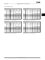
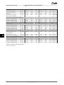
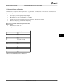
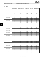
8.1 Mains Supply Specifications
98
8.1.1 Mains Supply 3x200-240 V AC
98
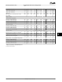
8.1.2 Mains Supply 3x380-480 V AC
99
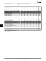
8.1.3 Mains Supply 3x380-480 V AC
103
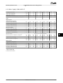
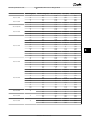
8.1.4 Mains Supply 3x525-600 V AC
105
8.2 General Specifications
106
8.3 Acoustic Noise or Vibration
109
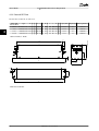
8.4 dU/Dt
110
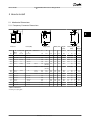
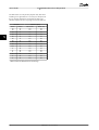
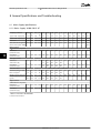
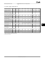
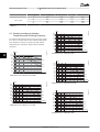
8.5 Derating according to Ambient Temperature and Switching Frequency
112
Index
4
94
118
MG18C502 - Rev. 2013-09-06
VLT® HVAC Basic Drive FC 101 Design Guide
Introduction
1 1
1 Introduction
1.1 Purpose of the Manual
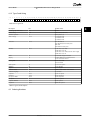
1.4 Abbreviations
This design guide provides information on how to select,
commission and order a frequency converter. It provides
information about mechanical and electrical installation.
Alternating current
AC
The design guide is intended for use by qualified
personnel.
Read and follow the design guide to use the frequency
converter safely and professionally, and pay particular
attention to the safety instructions and general warnings.
1.2 Document and Software Version
This manual is regularly reviewed and updated. All
suggestions for improvement are welcome. Table 1.1 shows
the document version and the corresponding software
version.
Edition
Remarks
Software version
MG18C5xx
Replaces MG18C4xx
2.51
Table 1.1 Document and Software Version
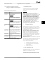
1.3 Safety Symbols
The following symbols are used in this document.
WARNING
Indicates a potentially hazardous situation which could
result in death or serious injury.
CAUTION
Indicates a potentially hazardous situation which could
result in minor or moderate injury. It may also be used
to alert against unsafe practices.
NOTICE
Indicates important information, including situations that
may result in damage to equipment or property.
American wire gauge
AWG
Ampere/AMP
A
Automatic Motor Adaptation
AMA
Current limit
ILIM
Degrees Celsius
°C
Direct current
DC
Electro Magnetic Compatibility
EMC
Electronic Thermal Relay
ETR
Frequency Converter
FC
Gram
g
Hertz
Hz
Kilohertz
kHz
Local Control Panel
LCP
Meter
m
Millihenry Inductance
mH
Milliampere
mA
Millisecond
ms
Minute
min
Motion Control Tool
MCT
Nanofarad
nF
Newton Meters
Nm
Nominal motor current
IM,N
Nominal motor frequency
fM,N
Nominal motor power
PM,N
Nominal motor voltage
UM,N
Protective Extra Low Voltage
PELV
Printed Circuit Board
PCB
Rated Inverter Output Current
IINV
Revolutions Per Minute
RPM
Regenerative terminals
Regen
Second
s
Synchronous Motor Speed
ns
Torque limit
TLIM
Volts
V
The maximum output current
IVLT,MAX
The rated output current supplied by the
frequency converter
IVLT,N
Table 1.2 Abbreviations
MG18C502 - Rev. 2013-09-06
5
1.5 Additional Resources
•
•
fM
The motor frequency.
VLT® HVAC Basic Drive FC 101 Quick Guide
VLT®
HVAC Basic Drive FC 101 Programming Guide
provides information on how to programme and
includes complete parameter descriptions.
•
VLT® HVAC Basic Drive FC 101 Design Guide entails
all technical information about the frequency
converter and customer design and applications.
•
MCT 10 Set-up Software enables the user to
configure the frequency converter from a
Windows™ based PC environment.
•
Danfoss VLT® Energy Box software at
www.danfoss.com/BusinessAreas/DrivesSolutions
then select PC Software Download.
VLT® Energy Box Software allows energy
consumption comparisons of HVAC fans and
pumps driven by Danfoss frequency converters
and alternative methods of flow control. This tool
may be used to project, as accurately as possible,
the costs, savings, and payback of using Danfoss
frequency converters on HVAC fans and pumps.
Danfoss technical literature is available in print from your
local Danfoss Sales Office or at:
www.danfoss.com/BusinessAreas/DrivesSolutions/
Documentations/Technical+Documentation.htm
fMAX
The maximum motor frequency.
fMIN
The minimum motor frequency.
fM,N
The rated motor frequency (nameplate data).
IM
The motor current.
IM,N
The rated motor current (nameplate data).
nM,N
The rated motor speed (nameplate data).
PM,N
The rated motor power (nameplate data).
UM
The instantaneous motor voltage.
UM,N
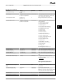
The rated motor voltage (nameplate data).
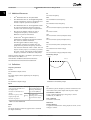
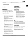
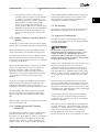
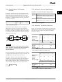
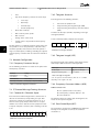
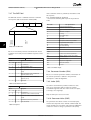
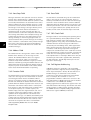
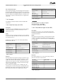
Break-away torque
Torque
175ZA078.10
1 1
VLT® HVAC Basic Drive FC 101 Design Guide
Introduction
Pull-out
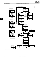
1.6 Definitions
Frequency Converter
IVLT,MAX
The maximum output current.
IVLT,N
The rated output current supplied by the frequency
converter.
UVLT, MAX
The maximum output voltage.
rpm
Illustration 1.1 Break-away Torque
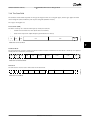
Input
The connected motor can
start and stop with LCP and
the digital inputs.
Functions are divided into 2
groups.
Functions in group 1 have
higher priority than
functions in group 2.
Group
1
Group
2
Reset, Coasting stop,
Reset and Coasting stop,
Quick-stop, DC braking,
Stop and the [Off] key.
Start, Pulse start,
Reversing, Start reversing,
Jog and Freeze output
Table 1.3 Control Commands
Motor
fJOG
The motor frequency when the jog function is activated
(via digital terminals).
6
ηVLT
The efficiency of the frequency converter is defined as the
ratio between the power output and the power input.
Start-disable command
A stop command belonging to the group 1 control
commands, see Table 1.3.
Stop command
See Control commands.
References
Analog reference
A signal transmitted to the analog inputs 53 or 54, can be
voltage or current.
MG18C502 - Rev. 2013-09-06
Introduction
VLT® HVAC Basic Drive FC 101 Design Guide
Bus reference
A signal transmitted to the serial communication port (FC
port).
Preset reference
A defined preset reference to be set from -100% to +100%
of the reference range. Selection of 8 preset references via
the digital terminals.
RefMAX
Determines the relationship between the reference input
at 100% full scale value (typically 10 V, 20 mA) and the
resulting reference. The maximum reference value set in
3-03 Maximum Reference.
RefMIN
Determines the relationship between the reference input
at 0% value (typically 0 V, 0 mA, 4 mA) and the resulting
reference. The minimum reference value set in
3-02 Minimum Reference
Miscellaneous
Analog inputs
The analog inputs are used for controlling various
functions of the frequency converter.
There are 2 types of analog inputs:
Current input, 0-20 mA and 4-20 mA
Voltage input, 0-10 V DC.
Analog outputs
The analog outputs can supply a signal of 0-20 mA, 4-20
mA, or a digital signal.
Automatic Motor Adaptation, AMA
AMA algorithm determines the electrical parameters for
the connected motor at standstill.
Digital inputs
The digital inputs can be used for controlling various
functions of the frequency converter.
Digital outputs
The frequency converter features 2 Solid State outputs that
can supply a 24 V DC (max. 40 mA) signal.
Relay outputs
The frequency converter features 2 programmable Relay
Outputs.
ETR
Electronic Thermal Relay is a thermal load calculation
based on present load and time. Its purpose is to estimate
the motor temperature.
Initialising
If initialising is carried out (14-22 Operation Mode), the
programmable parameters of the frequency converter
return to their default settings.
Initialising; 14-22 Operation Mode does not initialise
communication parameters.
Intermittent duty cycle
An intermittent duty rating refers to a sequence of duty
cycles. Each cycle consists of an on-load and an off-load
period. The operation can be either periodic duty or noneperiodic duty.
LCP
The Local Control Panel (LCP) makes up a complete
interface for control and programming of the frequency
converter. The control panel is detachable and can be
installed up to 3 m from the frequency converter, i.e. in a
front panel by means of the installation kit option.
lsb
Least significant bit.
MCM
Short for Mille Circular Mil, an American measuring unit for
cable cross-section. 1 MCM ≡ 0.5067 mm2.
msb
Most significant bit.
On-line/Off-line parameters
Changes to on-line parameters are activated immediately
after the data value is changed. Press [OK] to activate offline parameters.
PI controller
The PI controller maintains the desired speed, pressure,
temperature, etc. by adjusting the output frequency to
match the varying load.
RCD
Residual Current Device.
Set-up
Parameter settings in 2 set-ups can be saved. Change
between the 2 parameter set-ups and edit one set-up,
while another set-up is active.
Slip compensation
The frequency converter compensates for the motor slip
by giving the frequency a supplement that follows the
measured motor load keeping the motor speed almost
constant.
Smart Logic Control (SLC)
The SLC is a sequence of user defined actions executed
when the associated user defined events are evaluated as
true by the SLC.
Thermistor
A temperature-dependent resistor placed where the
temperature is to be monitored (frequency converter or
motor).
MG18C502 - Rev. 2013-09-06
7
1 1
1 1
VLT® HVAC Basic Drive FC 101 Design Guide
Introduction
Trip
A state entered in fault situations, e.g. if the frequency
converter is subject to an over-temperature or when the
frequency converter is protecting the motor, process or
mechanism. Restart is prevented until the cause of the
fault has disappeared and the trip state is cancelled by
activating reset or, in some cases, by being programmed
to reset automatically. Trip may not be used for personal
safety.
Trip locked
A state entered in fault situations when the frequency
converter is protecting itself and requiring physical
intervention, for example, if the frequency converter is
subject to a short circuit on the output. A locked trip can
only be cancelled by cutting off mains, removing the cause
of the fault, and reconnecting the frequency converter.
Restart is prevented until the trip state is cancelled by
activating reset or, in some cases, by being programmed
to reset automatically. Trip locked may not be used for
personal safety.
VT characteristics
Variable torque characteristics used for pumps and fans.
VVCplus
If compared with standard voltage/frequency ratio control,
Voltage Vector Control (VVCplus) improves the dynamics
and the stability, both when the speed reference is
changed and in relation to the load torque.
1.7 Power Factor
The power factor is the relation between I1 and IRMS.
Power factor =
3 × U × I1 × COS ϕ
3 × U × IRMS
The power factor for 3-phase control:
=
I1 × cos ϕ1
I1
=
since cos ϕ1 = 1
IRMS
IRMS
The power factor indicates to which extent the frequency
converter imposes a load on the mains supply.
The lower the power factor, the higher the IRMS for the
same kW performance.
IRMS = I12 + I52 + I72 + . . + In2
In addition, a high power factor indicates that the different
harmonic currents are low.
The frequency converters built-in DC coils produce a high
power factor, which minimizes the imposed load on the
mains supply.
8
MG18C502 - Rev. 2013-09-06
Product Overview
VLT® HVAC Basic Drive FC 101 Design Guide
2 Product Overview
2 2
Installation at high altitudes
CAUTION
2.1 Safety
At altitudes above 2 km, contact
Danfoss regarding PELV.
2.1.1 Safety Note
WARNING
WARNING
DANGEROUS VOLTAGE
The voltage of the frequency converter is dangerous
whenever connected to mains. Incorrect installation of
the motor, frequency converter or fieldbus may cause
death, serious personal injury or damage to the
equipment. Consequently, the instructions in this
manual, as well as national and local rules and safety
regulations, must be complied with.
Safety Regulations
1.
Disconnect the frequency converter from mains, if
repair work is to be carried out. Check that the
mains supply has been disconnected and that the
necessary time has passed before removing
motor and mains plugs.
2.
The [Off/Reset] key does not disconnect the
equipment from mains and is thus not to be used
as a safety switch.
3.
Correct protective earthing of the equipment
must be established, the user must be protected
against supply voltage, and the motor must be
protected against overload in accordance with
applicable national and local regulations.
4.
The earth leakage currents are higher than 3.5
mA.
5.
Protection against motor overload is set by
1-90 Motor Thermal Protection. If this function is
desired, set 1-90 Motor Thermal Protection to data
value [4], [6], [8], [10] ETR trip] or data value [3],
[5], [7], [9]ETR warning.
Note: The function is initialised at 1.16 x rated
motor current and rated motor frequency. For the
North American market: The ETR functions
provide class 20 motor overload protection in
accordance with NEC.
6.
Do not remove the plugs for the motor and
mains supply while the frequency converter is
connected to mains. Check that the mains supply
has been disconnected and that the necessary
time has elapsed before removing motor and
mains plugs.
7.
Check that all voltage inputs have been disconnected and that the necessary time has elapsed
before commencing repair work.
UNINTENDED START
1.
The motor can be brought to a stop with digital
commands, bus commands, references or a
local stop, while the frequency converter is
connected to mains. These stop functions are
not sufficient to avoid unintended start and
thus prevent personal injury.
2.
While parameters are being changed, the motor
may start. Consequently, always activate the
stop key [Off/Reset] before modifying data.
3.
A motor that has been stopped may start if
faults occur in the electronics of the frequency
converter, or if a temporary overload or a fault
in the supply mains or the motor connection
ceases.
WARNING
HIGH VOLTAGE
Frequency converters contain high voltage when
connected to AC mains input power. Installation, start
up, and maintenance should be performed by qualified
personnel only. Failure to perform installation, start up,
and maintenance by qualified personnel could result in
death or serious injury.
WARNING
UNINTENDED START
When the frequency converter is connected to AC mains,
the motor may start at any time. The frequency
converter, motor, and any driven equipment must be in
operational readiness. Failure to be in operational
readiness when the frequency converter is connected to
AC mains could result in death, serious injury,
equipment, or property damage.
MG18C502 - Rev. 2013-09-06
9
2 2
VLT® HVAC Basic Drive FC 101 Design Guide
Product Overview
WARNING
DISCHARGE TIME
Frequency converters contain DC-link capacitors that can
remain charged even when the frequency converter is
not powered. To avoid electrical hazards, disconnect AC
mains, any permanent magnet type motors, and any
remote DC-link power supplies, including battery
backups, UPS and DC-link connections to other
frequency converters. Wait for the capacitors to fully
discharge before performing any service or repair work.
The amount of wait time is listed in the Discharge Time
table. Failure to wait the specified time after power has
been removed before doing service or repair could result
in death or serious injury.
Voltage [V]
Power range [kW]
Minimum waiting time
[min]
3x200
0.25–3.7
4
15
3x200
5.5–45
3x400
0.37–7.5
4
3x400
11–90
15
3x600
2.2–7.5
4
3x600
11–90
15
converter. Danfoss do this by means of a manufacturer's
declaration.
The low-voltage directive (73/23/EEC)
Frequency converters must be CE labeled in accordance
with the low-voltage directive of January 1, 1997. The
directive applies to all electrical equipment and appliances
used in the 50-1000 V AC and the 75-1500 V DC voltage
ranges. Danfoss CE-labels in accordance with the directive
and issues a declaration of conformity upon request.
The EMC directive (89/336/EEC)
EMC is short for electromagnetic compatibility. The
presence of electromagnetic compatibility means that the
mutual interference between different components/
appliances does not affect the way the appliances work.
The EMC directive came into effect January 1, 1996.
Danfoss CE-labels in accordance with the directive and
issues a declaration of conformity upon request. To carry
out EMC-correct installation, see the instructions in this
Design Guide. In addition, Danfossspecifies which
standards our products comply with. Danfossoffers the
filters presented in the specifications and provide other
types of assistance to ensure the optimum EMC result.
The frequency converter is most often used by professionals of the trade as a complex component forming part
of a larger appliance, system or installation. It must be
noted that the responsibility for the final EMC properties of
the appliance, system or installation rests with the installer.
Table 2.1 Discharge Time
2.1.2 Disposal Instruction
Equipment containing electrical
components may not be disposed of
together with domestic waste.
It must be separately collected with
electrical and electronic waste according
to local and currently valid legislation.
2.2 CE Labeling
2.2.2 What is Covered
The EU "Guidelines on the Application of Council Directive
89/336/EEC" outline three typical situations of using a
frequency converter. See 2.2.3 Danfoss Frequency Converter
and CE Labeling for EMC coverage and CE labeling.
1.
The frequency converter is sold directly to the
end-consumer. The frequency converter is for
example sold to a DIY market. The end-consumer
is a layman. He installs the frequency converter
himself for use with a hobby machine, a kitchen
appliance, etc. For such applications, the
frequency converter must be CE labeled in
accordance with the EMC directive.
2.
The frequency converter is sold for installation in
a plant. The plant is built up by professionals of
the trade. It could be a production plant or a
heating/ventilation plant designed and installed
by professionals of the trade. Neither the
frequency converter nor the finished plant has to
be CE labeled under the EMC directive. However,
the unit must comply with the basic EMC
requirements of the directive. This is ensured by
using components, appliances, and systems that
are CE labeled under the EMC directive.
2.2.1 CE Conformity and Labeling
What is CE Conformity and Labeling?
The purpose of CE labeling is to avoid technical trade
obstacles within EFTA and the EU. The EU has introduced
the CE label as a simple way of showing whether a
product complies with the relevant EU directives. The CE
label says nothing about the specifications or quality of
the product. Frequency converters are regulated by three
EU directives:
The machinery directive (98/37/EEC)
All machines with critical moving parts are covered by the
machinery directive of January 1, 1995. Since a frequency
converter is largely electrical, it does not fall under the
machinery directive. However, if a frequency converter is
supplied for use in a machine, Danfoss provides
information on safety aspects relating to the frequency
10
MG18C502 - Rev. 2013-09-06
Product Overview
3.
VLT® HVAC Basic Drive FC 101 Design Guide
The frequency converter is sold as part of a
complete system. The system is being marketed
as complete and could for example, be an airconditioning system. The complete system must
be CE labeled in accordance with the EMC
directive. The manufacturer can ensure CE
labeling under the EMC directive either by using
CE labeled components or by testing the EMC of
the system. If only CE labeled components are
chosen, the entire system does not have to be
tested.
2.2.3 Danfoss Frequency Converter and CE
Labeling
CE labeling is a positive feature when used for its original
purpose, that is, to facilitate trade within the EU and EFTA.
However, CE labeling may cover many different specifications. Check what a given CE label specifically covers.
The covered specifications can be very different and a CE
label may therefore give the installer a false feeling of
security when using a frequency converter as a component
in a system or an appliance.
Danfoss CE labels the frequency converters in accordance
with the low-voltage directive. This means that if the
frequency converter is installed correctly, Danfoss
guarantees compliance with the low-voltage directive.
Danfoss issues a declaration of conformity that confirms
our CE labeling in accordance with the low-voltage
directive.
The CE label also applies to the EMC directive provided
that the instructions for EMC-correct installation and
filtering are followed. On this basis, a declaration of
conformity in accordance with the EMC directive is issued.
The Design Guide offers detailed instructions for installation to ensure EMC-correct installation. Furthermore,
Danfoss specifies which our different products comply
with.
Danfoss provides other types of assistance that can help to
obtain the best EMC result.
2.2.4 Compliance with EMC Directive
89/336/EEC
As mentioned, the frequency converter is mostly used by
professionals of the trade as a complex component
forming part of a larger appliance, system, or installation. It
must be noted that the responsibility for the final EMC
properties of the appliance, system or installation rests
with the installer. As an aid to the installer, Danfoss has
prepared EMC installation guidelines for the Power Drive
system. The standards and test levels stated for Power
Drive systems are complied with, if the EMC-correct
instructions for installation are followed.
2 2
2.3 Air Humidity
The frequency converter has been designed to meet the
IEC/EN 60068-2-3 standard, EN 50178 9.4.2.2 at 50 °C.
2.4 Aggressive Environments
A frequency converter contains many mechanical and
electronic components. All are to some extent vulnerable
to environmental effects.
CAUTION
The frequency converter should not be installed in
environments with airborne liquids, particles, or gases
capable of affecting and damaging the electronic
components. Failure to take the necessary protective
measures increases the risk of stoppages, thus reducing
the life of the frequency converter.
Liquids can be carried through the air and condense in the
frequency converter and may cause corrosion of
components and metal parts. Steam, oil, and salt water
may cause corrosion of components and metal parts. In
such environments, use equipment with enclosure rating
IP54. As an extra protection, coated printed circuit boards
can be ordered as an option. (Standard on some power
sizes.)
Airborne particles such as dust may cause mechanical,
electrical, or thermal failure in the frequency converter. A
typical indicator of excessive levels of airborne particles is
dust particles around the frequency converter fan. In dusty
environments, use equipment with enclosure rating IP54 or
a cabinet for IP20/TYPE 1 equipment.
In environments with high temperatures and humidity,
corrosive gases such as sulphur, nitrogen, and chlorine
compounds causes chemical processes on the frequency
converter components.
Such chemical reactions rapidly affects and damages the
electronic components. In such environments, mount the
equipment in a cabinet with fresh air ventilation, keeping
aggressive gases away from the frequency converter.
An extra protection in such areas is a coating of the
printed circuit boards, which can be ordered as an option.
MG18C502 - Rev. 2013-09-06
11
NOTICE
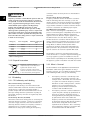
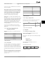
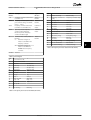
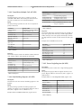
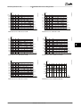
2.6.2 The Clear Advantage - Energy Savings
Before installing the frequency converter, check the
ambient air for liquids, particles, and gases. This is done by
observing existing installations in this environment. Typical
indicators of harmful airborne liquids are water or oil on
metal parts, or corrosion of metal parts.
The clear advantage of using a frequency converter for
controlling the speed of fans or pumps lies in the
electricity savings.
When comparing with alternative control systems and
technologies, a frequency converter is the optimum energy
control system for controlling fan and pump systems.
120
A
SYSTEM CURVE
100
PRESSURE%
Excessive dust particle levels are often found on installation cabinets and existing electrical installations. One
indicator of aggressive airborne gases is blackening of
copper rails and cable ends on existing installations.
130BA780.10
Mounting frequency converters in aggressive
environments increases the risk of stoppages and considerably reduces the life of the frequency converter.
80
2.5 Vibration and Shock
FAN CURVE
B
60
40
C
20
The frequency converter has been tested according to the
procedure based on the shown standards, Table 2.3
20
40
60
80
100 120
VOLUME%
Vibration (sinusoidal) - 1970
IEC/EN 60068-2-64
Vibration, broad-band random
SYSTEM CURVE
80
PRESSURE %
2.6 Advantages
180
120
100
Table 2.2 Standards
160
Illustration 2.1 Fan Curves (A, B, and C) for Reduced Fan
Volumes
A
IEC/EN 60068-2-6
140
130BA781.10
The frequency converter complies with requirements that
exist for units mounted on the walls and floors of
production premises, as well as in panels bolted to walls or
floors.
0
FAN CURVE
B
60
40
C
20
2.6.1 Why use a Frequency Converter for
Controlling Fans and Pumps?
0
A frequency converter takes advantage of the fact that
centrifugal fans and pumps follow the laws of proportionality for such fans and pumps. For further information
see 2.6.3 Example of Energy Savings.
20
40
60
80 100
Voume %
120
140
160
180
60
80
100
Voume %
120
140
160
180
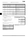
120
100
INPUT POWER %
2 2
VLT® HVAC Basic Drive FC 101 Design Guide
Product Overview
80
60
40
20
0
ENERGY
CONSUMED
20
40
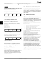
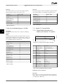
Illustration 2.2 When using a frequency converter to reduce
fan capacity to 60% - more than 50% energy savings may be
obtained in typical applications.
12
MG18C502 - Rev. 2013-09-06
VLT® HVAC Basic Drive FC 101 Design Guide
Product Overview
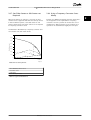
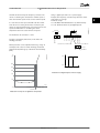
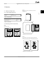
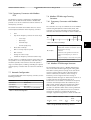
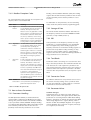
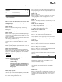
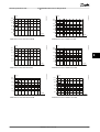
2.6.3 Example of Energy Savings
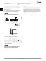
2.6.4 Comparison of Energy Savings
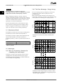
As shown in Illustration 2.3, the flow is controlled by
changing the RPM. By reducing the speed only 20% from
the rated speed, the flow is also reduced by 20%. This is
because the flow is directly proportional to the RPM. The
consumption of electricity, however, is reduced by 50%.
If the system in question only needs to be able to supply a
flow that corresponds to 100% a few days in a year, while
the average is below 80% of the rated flow for the
remainder of the year, the amount of energy saved is even
more than 50%.
The Danfoss frequency converter solution offers major
savings compared with traditional energy saving solutions.
This is because the frequency converter is able to control
fan speed according to thermal load on the system and
the fact that the frequency converter has a built-in facility
that enables the frequency converter to function as a
Building Management System, BMS.
Illustration 2.3 describes the dependence of flow, pressure and
power consumption on RPM.
P=Power
Q1=Rated flow
P1=Rated power
Q2=Reduced flow
P2=Reduced power
H=Pressure
n=Speed regulation
H1=Rated pressure
n1=Rated speed
H2=Reduced pressure
n2=Reduced speed
130BA782.10
Q=Flow
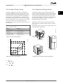
Illustration 2.5 shows typical energy savings obtainable
with 3 well-known solutions when fan volume is reduced
to i.e. 60%.
As the graph shows, more than 50% energy savings can be
achieved in typical applications.
Discharge
damper
175HA208.10
Table 2.3 The Laws of Proportionality
100%
Less energy savings
80%
50%
Flow ~n
Pressure ~n2
Maximum energy savings
25%
Power ~n3
12,5%
IGV
n
50%
Illustration 2.3 Laws of Proportionally
80% 100%
Costlier installation
Illustration 2.4 The 3 Common Energy Saving Systems
Q1
n1
=
Q2
n2
H1
n1 2
Pressure :
=
H2
n2
P1
n1 3
Power :
=
P2
n2
Flow :
( )
( )
MG18C502 - Rev. 2013-09-06
13
2 2
100
2 2
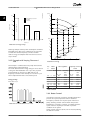
Discharge Damper Solution
A
20
60
0
60
0
1650rpm
1350rpm
C
10
Energy consumed
20
0
40
Energy consumed
40
B
30
Energy consumed
Input power %
50
VLT Solution
60
0
60
IGV Solution
80
Hs
(mwg)
175HA209.11
130BA779.11
VLT® HVAC Basic Drive FC 101 Design Guide
Product Overview
1050rpm
750rpm
0
200
300
400
(m3 /h)
Pshaft
(kW)
60
100
60
Volume %
50
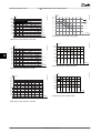
Illustration 2.5 Energy Savings
A1
40
Discharge dampers reduce power consumption somewhat.
Inlet Guide Vans offer a 40% reduction but are expensive
to install. The Danfoss frequency converter solution
reduces energy consumption with more than 50% and is
easy to install.
2.6.5 Example with Varying Flow over 1
Year
This example is calculated based on pump characteristics
obtained from a pump datasheet.
The result obtained shows energy savings in excess of 50%
at the given flow distribution over a year. The pay back
period depends on the price per kWh and price of
frequency converter. In this example it is less than a year
when compared with valves and constant speed.
Energy savings
Pshaft=Pshaft output
1650rpm
30
1350rpm
B1
20
10
C1
0
1050rpm
750rpm
100
200
400 (m3 /h)
300
Illustration 2.7 Energy
m3/
h
Distribution
%
Hours
350
5
438
300
15
250
20
200
Valve regulation
Consumption
Power
A1 - B1
kWh
A1 - C1
kWh
42.5
18.615
42.5
18.615
1314
38.5
50.589
29.0
38.106
1752
35.0
61.320
18.5
32.412
20
1752
31.5
55.188
11.5
20.148
150
20
1752
28.0
49.056
6.5
11.388
100
20
1752
23.0
40.296
3.5
Σ
Power
Frequency converter
control
100 8760
275.064
Consumption
6.132
26.801
Table 2.4 Result
2.6.6 Better Control
Illustration 2.6 Flow Distribution over 1 Year
14
If a frequency converter is used for controlling the flow or
pressure of a system, improved control is obtained.
A frequency converter can vary the speed of the fan or
pump, obtaining variable control of flow and pressure.
Furthermore, a frequency converter can quickly adapt the
speed of the fan or pump to new flow or pressure
conditions in the system.
Simple control of process (Flow, Level or Pressure) utilising
the built-in PI control.
MG18C502 - Rev. 2013-09-06
VLT® HVAC Basic Drive FC 101 Design Guide
Product Overview
2.6.7 Star/Delta Starter or Soft Starter not
Required
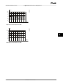
2.6.8 Using a Frequency Converter Saves
Money
When larger motors are started, it is necessary in many
countries to use equipment that limits the start-up current.
In more traditional systems, a star/delta starter or soft
starter is widely used. Such motor starters are not required
if a frequency converter is used.
Example 2.6.9 Without a Frequency Converter shows that a
lot of equipment is not required when a frequency
converter is used. It is possible to calculate the cost of
installing the 2 different systems. In the example, the 2
systems can be established at roughly the same price.
As illustrated in Illustration 2.8, a frequency converter does
not consume more than rated current.
175HA227.10
800
700
600
% Full load current
4
500
400
300
3
200
2
100
0
1
0
12,5
25
37,5
50Hz
Full load
& speed
Illustration 2.8 Start-up Current
1 VLT® HVAC Basic Drive FC 101
2 Star/delta starter
3 Soft-starter
4 Start directly on mains
Table 2.5 Legend to Illustration 2.8
MG18C502 - Rev. 2013-09-06
15
2 2
VLT® HVAC Basic Drive FC 101 Design Guide
Product Overview
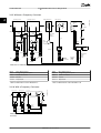
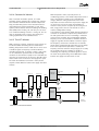
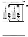
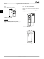
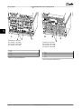
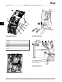
2.6.9 Without a Frequency Converter
Cooling section
Heating section
-
Inlet guide vane
Fan section
+
Return
Control
Flow
3-Port
valve
Return
Flow
3-Port
valve
Valve
position
Bypass
Supply
air
Fan
M
Bypass
V.A.V
Sensors
PT
outlets
Control
Mechanical
linkage
and vanes
Valve
position
x6
Pump
M
x6
IGV
Motor
or
actuator
Pump
M
x6
Starter
Starter
Duct
Local
D.D.C.
control
Starter
Control
Main
B.M.S
Fuses
Fuses
LV
supply
P.F.C
LV
supply
P.F.C
Power
Factor
Correction
Mains
Mains
Pressure
control
signal
0/10V
Temperature
control
signal
0/10V
Mains
Illustration 2.9 Traditional Fan System
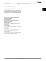
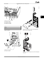
D.D.C.
Direct Digital Control
D.D.C.
Direct Digital Control
E.M.S.
Energy Management system
E.M.S.
Energy Management system
V.A.V.
Variable Air Volume
V.A.V.
Variable Air Volume
Sensor P
Pressure
Sensor P
Pressure
Sensor T
Temperature
Sensor T
Temperature
Table 2.6 Abbreviations used in Illustration 2.9
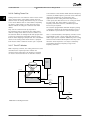
Table 2.7 Abbreviations used in Illustration 2.10
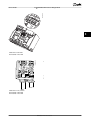
Cooling section
Heating section
Fan section
-
+
Fan
M
Return
Flow
Return
Supply
air
Sensors
PT
V.A.V
outlets
Flow
175HA206.11
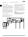
2.6.10 With a Frequency Converter
x3
M
VLT
Pump
x3
M
Duct
Pump
x3
VLT
Control
temperature
0-10V
or
Mains 0/4-20mA Mains
VLT
Control
temperature
0-10V
or
0/4-20mA
Mains
Pressure
control
0-10V
or
0/4-20mA
Local
D.D.C.
control
Main
B.M.S
Illustration 2.10 Fan System Controlled by Frequency
Converters
16
MG18C502 - Rev. 2013-09-06
175HA205.12
2 2
Product Overview
VLT® HVAC Basic Drive FC 101 Design Guide
2.6.11 Application Examples
2 2
The next pages provide typical examples of applications
within HVAC.
For further information about a given application, ask the
Danfoss supplier for an information sheet that gives a full
description of the application. The following application
notes can be downloaded from the Danfoss web page,
www.danfoss.com/BusinessAreas/DrivesSolutions/
Documentations/Technical+Documentation.htm
Variable Air Volume
Ask for The Drive to...Improving Variable Air Volume
Ventilation Systems, MN60A.
Constant Air Volume
Ask for The Drive to...Improving Constant Air Volume
Ventilation Systems, MN60B.
Cooling Tower Fan
Ask for The Drive to...Improving fan control on cooling
towers, MN60C.
Condenser pumps
Ask for The Drive to...Improving condenser water pumping
systems, MN60F.
Primary pumps
Ask for The Drive to...Improve your primary pumping in
primary/secondary pumping systems, MN60D.
Secondary pumps
Ask for The Drive to...Improve your secondary pumping in
primary/secondary pumping systems, MN60E.
MG18C502 - Rev. 2013-09-06
17
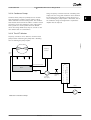
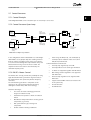
2.6.12 Variable Air Volume
VAV, or Variable Air Volume systems, control both the
ventilation and temperature to satisfy the requirements of
a building. Central VAV systems are considered to be the
most energy efficient method to air condition buildings. By
designing central systems instead of distributed systems, a
greater efficiency can be obtained.
The efficiency comes from utilising larger fans and larger
chillers which have much higher efficiencies than small
motors and distributed air-cooled chillers. Savings are also
seen from the decreased maintenance requirements.
the installation. Instead of creating an artificial pressure
drop or causing a decrease in fan efficiency, the frequency
converter decreases the speed of the fan to provide the
flow and pressure required by the system.
Centrifugal devices such as fans behave according to the
centrifugal laws. This means the fans decrease the pressure
and flow they produce as their speed is reduced. Their
power consumption is thereby significantly reduced.
The PI controller of the VLT® HVAC Basic Drive can be used
to eliminate the need for additional controllers.
2.6.13 The VLT Solution
While dampers and IGVs work to maintain a constant
pressure in the ductwork, a frequency converter solution
saves much more energy and reduces the complexity of
Cooling coil
Heating coil
Filter
Frequency
converter
130BB455.10
2 2
VLT® HVAC Basic Drive FC 101 Design Guide
Product Overview
Pressure
signal
VAV boxes
Supply fan
D1
3
T
Flow
D2
Frequency
converter
Return fan
3
D3
Illustration 2.11 Variable Air Volume
18
MG18C502 - Rev. 2013-09-06
Flow
Pressure
transmitter
VLT® HVAC Basic Drive FC 101 Design Guide
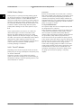
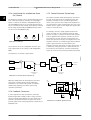
2.6.14 Constant Air Volume
CAV, or Constant Air Volume systems, are central
ventilation systems usually used to supply large common
zones with the minimum amounts of fresh tempered air.
They preceded VAV systems and are therefore found in
older multi-zoned commercial buildings as well. These
systems preheat amounts of fresh air utilising Air Handling
Units (AHUs) with a heating coil, and many are also used
to air condition buildings and have a cooling coil. Fan coil
units are frequently used to assist in the heating and
cooling requirements in the individual zones.
2.6.15 The VLT Solution
With a frequency converter, significant energy savings can
be obtained while maintaining decent control of the
building. Temperature sensors or CO2 sensors can be used
as feedback signals to frequency converters. Whether
controlling temperature, air quality, or both, a CAV system
can be controlled to operate based on actual building
conditions. As the number of people in the controlled area
decreases, the need for fresh air decreases. The CO2 sensor
detects lower levels and decreases the supply fans speed.
The return fan modulates to maintain a static pressure
setpoint or fixed difference between the supply and return
air flows.
Cooling coil
Heating coil
Filter
With temperature control, especially used in air
conditioning systems, as the outside temperature varies as
well as the number of people in the controlled zone
changes, different cooling requirements exist. As the
temperature decreases below the set-point, the supply fan
can decrease its speed. The return fan modulates to
maintain a static pressure set-point. By decreasing the air
flow, energy used to heat or cool the fresh air is also
reduced, adding further savings.
Several features of the Danfoss HVAC dedicated frequency
converter can be utilised to improve the performance of
the CAV system. One concern of controlling a ventilation
system is poor air quality. The programmable minimum
frequency can be set to maintain a minimum amount of
supply air regardless of the feedback or reference signal.
The frequency converter also includes one PI controller,
which allows monitoring both temperature and air quality.
Even if the temperature requirement is satisfied, the
frequency converter maintains enough supply air to satisfy
the air quality sensor. The controller is capable of
monitoring and comparing 2 feedback signals to control
the return fan by maintaining a fixed differential air flow
between the supply and return ducts as well.
Frequency
converter
130BB451.10
Product Overview
Temperature
signal
Supply fan
D1
Temperature
transmitter
D2
Pressure
signal
Frequency
converter
Return fan
Pressure
transmitter
D3
Illustration 2.12 Constant Air Volume
MG18C502 - Rev. 2013-09-06
19
2 2
2.6.16 Cooling Tower Fan
Cooling Tower Fans cool condenser water in water cooled
chiller systems. Water cooled chillers provide the most
efficient means of creating chilled water. They are as much
as 20% more efficient than air cooled chillers. Depending
on climate, cooling towers are often the most energy
efficient method of cooling the condenser water from
chillers.
They cool the condenser water by evaporation.
The condenser water is sprayed into the cooling tower
until the cooling towers “fill” to increase its surface area.
The tower fan blows air through the fill and sprayed water
to aid in the evaporation. Evaporation removes energy
from the water dropping its temperature. The cooled water
collects in the cooling towers basin where it is pumped
back into the chillers condenser and the cycle is repeated.
2.6.17 The VLT Solution
Several features of the Danfoss HVAC dedicated frequency
converter, the HVAC frequency converter can be utilised to
improve the performance of cooling tower fans
applications. As the cooling tower fans drop below a
certain speed, the effect the fan has on cooling the water
becomes small. Also, when utilising a gear-box to
frequency control the tower fan, a minimum speed of
40-50% may be required.
The customer programmable minimum frequency setting
is available to maintain this minimum frequency even as
the feedback or speed reference calls for lower speeds.
Also as a standard feature, the frequency converter can be
programmed to enter a “sleep” mode and stop the fan
until a higher speed is required. Additionally, some cooling
tower fans have undesireable frequencies that may cause
vibrations. These frequencies can easily be avoided by
programming the bypass frequency ranges in the
frequency converter.
130BB453.10
With a frequency converter, the cooling towers fans can be
controlled to the required speed to maintain the
condenser water temperature. The frequency converters
can also be used to turn the fan on and off as needed.
Frequency
converter
Water Inlet
Temperature
Sensor
BASIN
Water Outlet
Conderser
Water pump
CHILLER
2 2
VLT® HVAC Basic Drive FC 101 Design Guide
Product Overview
Supply
Illustration 2.13 Cooling Tower Fan
20
MG18C502 - Rev. 2013-09-06
VLT® HVAC Basic Drive FC 101 Design Guide
Product Overview
2.6.18 Condenser Pumps
Condenser water pumps are primarily used to circulate
water through the condenser section of water cooled
chillers and their associated cooling tower. The condenser
water absorbs the heat from the chiller's condenser section
and releases it into the atmosphere in the cooling tower.
These systems are used to provide the most efficient
means of creating chilled water, they are as much as 20%
more efficient than air cooled chillers.
Using a frequency converter instead of a throttling valve
simply saves the energy that would have been absorbed
by the valve. This can amount to savings of 15-20% or
more. Trimming the pump impeller is irreversible, thus if
the conditions change and higher flow is required the
impeller must be replaced.
2 2
2.6.19 The VLT Solution
130BB452.10
Frequency converters can be added to condenser water
pumps instead of balancing the pumps with a throttling
valve or trimming the pump impeller.
Frequency
converter
Water
Inlet
Flow or pressure sensor
BASIN
CHILLER
Water
Outlet
Condenser
Water pump
Throttling
valve
Supply
Illustration 2.14 Condenser Pumps
MG18C502 - Rev. 2013-09-06
21
2 2
Product Overview
VLT® HVAC Basic Drive FC 101 Design Guide
2.6.20 Primary Pumps
Primary pumps in a primary/secondary pumping system
can be used to maintain a constant flow through devices
that encounter operation or control difficulties when
exposed to variable flow. The primary/secondary pumping
technique decouples the “primary” production loop from
the “secondary” distribution loop. This allows devices such
as chillers to obtain constant design flow and operate
properly while allowing the rest of the system to vary in
flow.
As the evaporator flow rate decreases in a chiller, the
chilled water begins to become over-chilled. As this
happens, the chiller attempts to decrease its cooling
capacity. If the flow rate drops far enough, or too quickly,
the chiller cannot shed its load sufficiently and the chiller’s
safety trips the chiller requiring a manual reset. This
situation is common in large installations especially when 2
or more chillers in parallel are installed if primary/
secondary pumping is not utilised.
2.6.21 The VLT Solution
Depending on the size of the system and the size of the
primary loop, the energy consumption of the primary loop
can become substantial.
A frequency converter can be added to the primary
system, to replace the throttling valve and/or trimming of
the impellers, leading to reduced operating expenses. Two
control methods are common:
22
Flow meter
Because the desired flow rate is known and is constant, a
flow meter installed at the discharge of each chiller, can be
used to control the pump directly. Using the built-in PI
controller, the frequency converter always maintains the
appropriate flow rate, even compensating for the changing
resistance in the primary piping loop as chillers and their
pumps are staged on and off.
Local speed determination
The operator simply decreases the output frequency until
the design flow rate is achieved.
Using a frequency converter to decrease the pump speed
is very similar to trimming the pump impeller, except it
does not require any labor and the pump efficiency
remains higher. The balancing contractor simply decreases
the speed of the pump until the proper flow rate is
achieved and leaves the speed fixed. The pump operates
at this speed any time the chiller is staged on. Because the
primary loop does not have control valves or other devices
that can cause the system curve to change and the
variance due to staging pumps and chillers on and off is
usually small, this fixed speed remains appropriate. In the
event the flow rate needs to be increased later in the
systems life, the frequency convertercan simply increase
the pump speed instead of requiring a new pump
impeller.
MG18C502 - Rev. 2013-09-06
Flowmeter
Flowmeter
Frequency
converter
CHILLER
F
CHILLER
F
130BB456.10
VLT® HVAC Basic Drive FC 101 Design Guide
Product Overview
Frequency
converter
Illustration 2.15 Primary Pumps
MG18C502 - Rev. 2013-09-06
23
2 2
2.6.22 Secondary Pumps
Secondary pumps in a primary/secondary chilled water
pumping system distribute the chilled water to the loads
from the primary production loop. The primary/secondary
pumping system is used to hydronically de-couple one
piping loop from another. In this case, the primary pump is
used to maintain a constant flow through the chillers while
allowing the secondary pumps to vary in flow, increase
control and save energy.
If the primary/secondary design concept is not used and a
variable volume system is designed, when the flow rate
drops far enough or too quickly, the chiller cannot shed its
load properly. The chiller’s low evaporator temperature
safety then trips the chiller requiring a manual reset. This
situation is common in large installations especially when 2
or more chillers in parallel are installed.
2.6.23 The VLT Solution
With the proper sensor location, the addition of frequency
converters allows the pumps to vary their speed to follow
the system curve instead of the pump curve.
This results in the elimination of wasted energy and
eliminates most of the over-pressurization, 2-way valves
can be subjected too.
As the monitored loads are reached, the 2-way valves close
down. This increases the differential pressure measured
across the load and 2-way valve. As this differential
pressure starts to rise, the pump is slowed to maintain the
control head also called setpoint value. This set-point value
is calculated by summing the pressure drop of the load
and two way valve together under design conditions.
NOTICE
When running multiple pumps in parallel, they must run
at the same speed to maximize energy savings, either
with individual dedicated drives or one frequency
converter running multiple pumps in parallel.
P
Frequency
converter
CHILLER
3
Frequency
converter
3
Illustration 2.16 Secondary Pumps
24
MG18C502 - Rev. 2013-09-06
130BB454.10
While the primary-secondary system with 2-way valves
improves energy savings and eases system control
problems, the true energy savings and control potential is
realised by adding frequency converters.
CHILLER
2 2
VLT® HVAC Basic Drive FC 101 Design Guide
Product Overview
VLT® HVAC Basic Drive FC 101 Design Guide
Product Overview
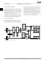
2.7 Control Structures
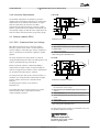
2.7.1 Control Principle
2 2
1-00 Configuration Mode can be selected if open or closed loop is to be used.
130BB892.10
2.7.2 Control Structure Open Loop
100%
Reference
handling
Remote
reference
P 4-14
Motor speed
high limit [Hz]
Auto mode
Hand mode
P 3-4* Ramp 1
P 3-5* Ramp 2
Remote
Reference
0%
To motor
control
Ramp
Local
Local
reference
scaled to
Hz
100%
P 4-12
Motor speed
low limit [Hz]
-100%
LCP Hand on,
off and auto
on keys
P 4-10
Motor speed
direction
Illustration 2.17 Open Loop Structure
In the configuration shown in Illustration 2.17, 1-00 Configuration Mode is set to [0] Open loop. The resulting reference
from the reference handling system or the local reference
is received and fed through the ramp limitation and speed
limitation before being sent to the motor control. The
output from the motor control is then limited by the
maximum frequency limit.
2.7.3 PM/EC+ Motor Control
The Danfoss EC+ concept provides the possibitily for using
high efficient PM motors (permanent magnet motors) in
IEC standard frame size operated by Danfoss frequency
converters.
The commissioning procedure is comparable to the
existing one for asynchronous (induction) motors by
utilising the Danfoss VVCplus PM control strategy.
•
Power range: 45 kW (200 V), 0.37-90 kW (400 V),
90 kW (600 V) for induction motors and 0.37-22
kW (400 V) for PM motors.
Current limitations for PM motors:
• Currently only supported up to 22 kW
•
•
•
Currently limited to non salient type PM motors
LC filters not supported together with PM motors
Over Voltage Control algorithm is not supported
with PM motors
•
Kinetic backup algorithm is not supported with
PM motors
•
Support reduced AMA of the stator resistance Rs
in the system only
•
•
No stall detection
No ETR function
Customer advantages:
• Free choice of motor technology (permanent
magnet or induction motor)
•
Installation and operation as know on induction
motors
•
Manufacturer independent when selecting system
components (e.g. motors)
•
Best system efficiency by selecting best
components
•
Possible retrofit of existing installations
MG18C502 - Rev. 2013-09-06
25
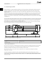
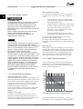
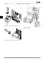
2.7.5 Control Structure Closed Loop
2.7.4 Local (Hand On) and Remote (Auto
On) Control
The frequency converter can be operated manually via the
local control panel (LCP) or remotely via analog/digital
inputs or serial bus. If allowed in 0-40 [Hand on] Key on
LCP, 0-44 [Off/Reset] Key on LCP, and 0-42 [Auto on] Key on
LCP, it is possible to start and stop the frequency converter
by LCP using the [Hand On] and [Off/Reset] keys. Alarms
can be reset via the [Off/Reset] key.
Hand
On
Off
Reset
130BB893.10
Auto
On
Illustration 2.18 LCP Keys
Local reference forces the configuration mode to open
loop, independent on the setting of 1-00 Configuration
Mode.
The internal controller allows the frequency converter to
become an integral part of the controlled system. The
frequency converter receives a feedback signal from a
sensor in the system. It then compares this feedback to a
set-point reference value and determines the error, if any,
between these 2 signals. It then adjusts the speed of the
motor to correct this error.
For example, consider a pump application where the
speed of a pump is to be controlled so that the static
pressure in a pipe is constant. The desired static pressure
value is supplied to the frequency converter as the setpoint reference. A static pressure sensor measures the
actual static pressure in the pipe and supplies this to the
frequency converter as a feedback signal. If the feedback
signal is greater than the set-point reference, the
frequency converter slows down to reduce the pressure. In
a similar way, if the pipe pressure is lower than the setpoint reference, the frequency converter automatically
speed up to increase the pressure provided by the pump.
130BB894.11
Local Reference is restored at power-down.
100%
Reference
+
0%
S
_
Scale to
speed
PI
*[-1]
To motor
control
100%
Feedback
-100%
7-30 PI
Normal/Inverse
Control
P 4-10
Motor speed
direction
Illustration 2.19 Control Structure Closed Loop
While the default values for the frequency converter’s
Closed Loop controller often provides satisfactory
performance, the control of the system can often be
optimized by adjusting some of the Closed Loop
controller’s parameters.
Ref.
signal
Ref. +
-
PI
P 20-01
Desired
flow
FB conversion
FB
P
Flow
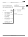
2.7.6 Feedback Conversion
In some applications it may be useful to convert the
feedback signal. One example of this is using a pressure
signal to provide flow feedback. Since the square root of
pressure is proportional to flow, the square root of the
pressure signal yields a value proportional to the flow. See
Illustration 2.20.
26
130BB895.10
2 2
VLT® HVAC Basic Drive FC 101 Design Guide
Product Overview
Flow
P
FB
signal
P
Illustration 2.20 Feedback Signal Conversion
MG18C502 - Rev. 2013-09-06
VLT® HVAC Basic Drive FC 101 Design Guide
Product Overview
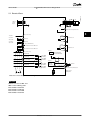
2.7.7 Reference Handling
2 2
Details for Open Loop and Closed Loop operation.
Intern resource
130BB900.13
Relative scalling reference
Preset relative reference
±100%
Preset reference 0 ±100%
Preset reference 1 ±100%
Preset reference 2 ±100%
Preset reference 3 ±100%
Preset reference 4 ±100%
Preset reference 5 ±100%
Preset reference 6 ±100%
Preset reference 7 ±100%
Input command:
preset ref bit0, bit1, bit2
Speed open
loop
Preset reference
Input command:
freeze reference
±100%
Y
Extern resource 1
No function
Parameter choise:
Reference resource 1,2,3
Configuration
mode
+
Analog reference
±200 %
X
Relative
reference
=
X+X*Y/100
Remote
reference/
setpoint
maxRefPCT
±200%
minRefPct
±200%
min-max ref
Process
control
±100%
Local bus reference
±200 %
LCP potmeter 0~100 %
Freeze
reference &
increase/
decrease
reference
+
Scale to
process
unit
Input commands:
±200%
Speed up/speed down
Extern resource 2
±200%
No function
Feedback
handling
Analog reference
±200 %
Local bus reference
±200 %
LCP potmeter 0~100 %
Scale to
Hz
External reference in %
Remote
reference in %
Extern resource 3
No function
Analog reference
±200 %
Local bus reference
±200 %
LCP potmeter 0~100 %
Illustration 2.21 Block Diagram Showing Remote Reference
The remote reference is comprised of:
•
•
Preset references
•
•
The preset relative reference
External references (analog inputs and serial
communication bus references)
reference. The external reference, the preset reference or
the sum of the 2 can be selected to be the active
reference. Finally, this reference can by be scaled using
3-14 Preset Relative Reference.
The scaled reference is calculated as follows:
Reference = X + X ×
Feedback controlled setpoint
Up to 8 preset references can be programmed in the
frequency converter. The active preset reference can be
selected using digital inputs or the serial communications
bus. The reference can also be supplied externally, most
commonly from an analog input. This external source is
selected by one of the 3 Reference Source parameters
(3-15 Reference 1 Source, 3-16 Reference 2 Source and
3-17 Reference 3 Source). All reference resources and the
bus reference are added to produce the total external
Y
( 100
)
Where X is the external reference, the preset reference or
the sum of these and Y is 3-14 Preset Relative Reference in
[%].
If Y, 3-14 Preset Relative Reference, is set to 0%, the
reference is not affected by the scaling.
MG18C502 - Rev. 2013-09-06
27
VLT® HVAC Basic Drive FC 101 Design Guide
Product Overview
2 2
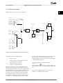
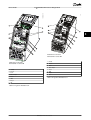
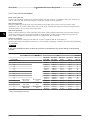
PM motor
1
0-03 Regional Settings
[0] Power kW/50 Hz
2
0-06 Grid Type
[0] 200-240V/50Hz/Delta
3
1-00 Configuration Mode
[3] Closed Loop
4
1-10 Motor Type
[0] Asynchronous
10
1-20 Motor Power
1.10 kW
5
11
1-25 Motor nominal speed
3000 RPM
1-22 Motor Voltage
0050 V
6
12
1-26 Motor Cont. Rated Torque
5.4 Nm
1-23 Motor frequency
0050 Hz
7
13
1-30 Stator resistance
0.65 Ohms
1-24 Motor current
04.66 A
8
14
1-39 Motor poles
8
1-25 Motor nominal speed
1420 RPM
9
15
1-40 Back EMF at 1000 rpm
57 V
16
1-37 d-axis inductance(Ld)
5 mH
17
4-19 Max Ouput Frequency
0065 Hz
Current
31
6-22 T54 Low Current
04.66 A
32
6-24 T54 low Feedback
0016 Hz
34
18
4-12 Motor speed low limit
0016 Hz
19
4-13 Motor speed high limit
0050 Hz
20
3-41 Ramp 1 ramp-up time
0003 s
21
3-42 Ramp1 ramp-down time
0003 s
6-23 T54 high Current
13.30 A
22a
20-00 Feedback 1 source
[1] Analog input 54
22b
3-16 Reference Source 2
[0] No Operation
23
3-02 Min Reference
0.00
24
3-03 Max Reference
50.00
25
3-10 Preset reference [0]
0.00 %
26
6-29 Terminal 54 Mode
[1] Voltage
35
6-26 T54 Filter time const.
0.01 s
36
20-81 PI Normal/Inverse Control
[0] Normal
37
20-83 PI Normal/Inverse Control
0050 Hz
38
20-93 PI Proportional Gain
00.50
39
20-94 PI integral time
0020.00 s
40
1-29 Automatic Motor Adaption
[0] Off
6-25 T54 high Feedback
0050 Hz
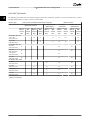
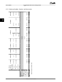
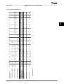
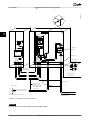
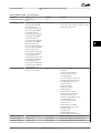
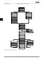
Illustration 2.22 Closed Loop Set-up Wizard
28
Asynchronous Motor
1-24 Motor Current
3.8 A
MotorType = PM Motor
33
130BC402.10
2.7.8 Closed Loop Set-up Wizard
MG18C502 - Rev. 2013-09-06
MotorType = Asynchronous
22
1-73 Flying Start
[0] No
This dialog is forced to be set to
[1] Analog input 54
Voltage
6-20 T54 low Voltage
0050 V
27
6-24 T54 low Feedback
0016 Hz
28
6-21 T54 high Voltage
0220 V
29
6-25 T54 high Feedback
0050 Hz
30
VLT® HVAC Basic Drive FC 101 Design Guide
Product Overview
Closed Loop Set-up Wizard
Parameter
Range
Default
0-03 Regional Settings
[0] International
[1] US
0
Function
0-06 GridType
[0] -[[132] see start -up wizard
for open loop application
Size selected
Select operating mode for restart upon
reconnection of the frequency converter to
mains voltage after power down
1-00 Configuration Mode
[0] Open loop
[3] Closed loop
0
Change this parameter to Closed loop
1-10 Motor Construction
*[0] Motor construction
[1] PM, non salient SPM
[0] Asynchron
Setting the parameter value might change
these parameters:
1-01 Motor Control Principle
1-03 Torque Characteristics
1-14 Damping Gain
1-15 Low Speed Filter Time Const
1-16 High Speed Filter Time Const
1-17 Voltage filter time const
1-20 Motor Power
1-22 Motor Voltage
1-23 Motor Frequency
1-25 Motor Nominal Speed
1-26 Motor Cont. Rated Torque
1-30 Stator Resistance (Rs)
1-33 Stator Leakage Reactance (X1)
1-35 Main Reactance (Xh)
1-37 d-axis Inductance (Ld)
1-39 Motor Poles
1-40 Back EMF at 1000 RPM
1-66 Min. Current at Low Speed
1-72 Start Function
2 2
1-73 Flying Start
4-19 Max Output Frequency
4-58 Missing Motor Phase Function
1-20 Motor Power
0.09-110 kW
Size related
1-22 Motor Voltage
50.0-1000.0 V
Size related
Enter motor power from nameplate data
Enter motor voltage from nameplate data
1-23 Motor Frequency
20.0-400.0 Hz
Size related
Enter motor frequency from nameplate data
1-24 Motor Current
0.0 -10000.00 A
Size related
Enter motor current from nameplate data
1-25 Motor Nominal Speed
100.0-9999.0 RPM
Size related
Enter motor nominal speed from nameplate
data
1-26 Motor Cont. Rated Torque
0.1-1000.0
Size related
This parameter is available only when
1-10 Motor Construction Design is set to [1]
PM, non-salient SPM.
NOTICE
Changing this parameter affects
settings of other parameters
1-29 Automatic Motor Adaption
(AMA)
Off
Performing an AMA optimizes motor
performance
1-30 Stator Resistance (Rs)
0.000-99.990
Size related
Set the stator resistance value
1-37 d-axis Inductance (Ld)
0-1000
Size related
Enter the value of the d-axis inductance.
Obtain the value from the permanent magnet
motor data sheet. The de-axis inductance
cannot be found by performing an AMA.
1-39 Motor Poles
2-100
4
Enter the number of motor poles
1-40 Back EMF at 1000 RPM
10-9000
Size related
Line-Line RMS back EMF voltage at 1000 RPM
MG18C502 - Rev. 2013-09-06
29
VLT® HVAC Basic Drive FC 101 Design Guide
Product Overview
Parameter
Range
Default
Function
1-73 Flying Start
[0] Disabled
[1] Enabled
0
Select [1] Enable to enable the frequency
converter to catch a spinning motor. I.e. fan
applications. When PM is selected, Flying Start
is enabled.
3-02 Minimum Reference
-4999-4999
0
The minimum reference is the lowest value
obtainable by summing all references
3-03 Maximum Reference
-4999-4999
50
The maximum reference is the highest value
obtainable by summing all references
2 2
3-10 Preset Reference
-100-100%
0
Enter the set point
3-41 Ramp 1 Ramp Up Time
0.05-3600.0 s
Size related
Ramp up time from 0 to rated 1-23 Motor
Frequency if Asynchron motor is selected;
ramp up time from 0 to 1-25 Motor Nominal
Speed if PM motor is selected"
3-42 Ramp 1 Ramp Down Time
0.05-3600.0 s
Size related
Ramp down time from rated 1-23 Motor
Frequency to 0 if Asynchron motor is selected;
ramp down time from 1-25 Motor Nominal
Speed to 0 if PM motor is selected
4-12 Motor Speed Low Limit [Hz]
0.0-400 Hz
0.0 Hz
Enter the minimum limit for low speed
4-14 Motor Speed High Limit [Hz]
0-400 Hz
65 Hz
Enter the minimum limit for high speed
4-19 Max Output Frequency
0-400
Size related
Enter the maximum output frequency value
6-20 Terminal 54 Low Voltage
0-10 V
0.07 V
Enter the voltage that corresponds to the low
reference value
6-21 Terminal 54 High Voltage
0-10 V
10 V
Enter the voltage that corresponds to the low
high reference value
6-22 Terminal 54 Low Current
0-20 mA
4
Enter the current that corresponds to the high
reference value
6-23 Terminal 54 High Current
0-20 mA
20
Enter the current that corresponds to the high
reference value
6-24 Terminal 54 Low Ref./Feedb.
Value
-4999-4999
0
Enter the feedback value that corresponds to
the voltage or current set in 6-20 Terminal 54
Low Voltage/6-22 Terminal 54 Low Current
6-25 Terminal 54 High Ref./Feedb.
Value
-4999-4999
50
Enter the feedback value that corresponds to
the voltage or current set in 6-21 Terminal 54
High Voltage/6-23 Terminal 54 High Current
6-26 Terminal 54 Filter Time
Constant
0-10 s
0.01
Enter the filter time comstant
6-29 Terminal 54 mode
[0] Current
[1] Voltage
1
Select if terminal 54 is used for current- or
voltage input
20-81 PI Normal/ Inverse Control
[0] Normal
[1] Inverse
0
Select [0] Normal to set the process control to
increase the output speed when the process
error is positive. Select [1] Inverse to reduce
the output speed.
20-83 PI Start Speed [Hz]
0-200 Hz
0
Enter the motor speed to be attained as a
start signal for commencement of PI control
20-93 PI Proportional Gain
0-10
0.01
Enter the process controller proportional gain.
Quick control is obtained at high amplification. However if amplification is too great,
the process may become unstable
20-94 PI Integral Time
0.1-999.0 s
999.0 s
Enter the process controller integral time.
Obtain quick control through a short integral
time, though if the integral time is too short,
the process becomes unstable. An excessively
long integral time disables the integral action.
Table 2.8 Closed Loop Set-up Wizard
30
MG18C502 - Rev. 2013-09-06
Product Overview
VLT® HVAC Basic Drive FC 101 Design Guide
2.7.9 Tuning the Drive Closed Loop Controller
Once the frequency converter's closed loop controller has been set up, the performance of the controller should be tested.
In many cases, its performance may be acceptable using the default values of 20-93 PI Proportional Gain and 20-94 PI Integral
Time. However, in some cases it may be helpful to optimize these parameter values to provide faster system response while
still controlling speed overshoot.
2.7.10 Manual PI Adjustment
1.
Start the motor.
2.
Set 20-93 PI Proportional Gain to 0.3 and increase it until the feedback signal begins to oscillate. If necessary, start
and stop the frequency converter or make step changes in the set-point reference to attempt to cause oscillation.
Next reduce the PI proportional gain until the feedback signal stabilises. Then reduce the proportional gain by
40-60%.
3.
Set 20-94 PI Integral Time to 20 s and reduce it until the feedback signal begins to oscillate. If necessary, start and
stop the frequency converter or make step changes in the set-point reference to attempt to cause oscillation. Next,
increase the PI integral time until the feedback signal stabilises. Then increase of the integral time by 15-50%.
MG18C502 - Rev. 2013-09-06
31
2 2
2.8 General Aspects of EMC
Electrical interference is usually conducted at frequencies in the range 150 kHz to 30 MHz. Airborne interference from the
frequency converter system in the range 30 MHz to 1 GHz is generated from the inverter, motor cable, and the motor.
As shown in Illustration 2.23, capacitance in the motor cable coupled with a high dU/dt from the motor voltage generate
leakage currents.
The use of a screened motor cable increases the leakage current (see Illustration 2.23) because screened cables have higher
capacitance to earth than unscreened cables. If the leakage current is not filtered, it causes greater interference on the
mains in the radio frequency range below approximately 5 MHz. Since the leakage current (I1) is carried back to the unit
through the screen (I3), there is in principle only a small electro-magnetic field (I4) from the screened motor cable according
to Illustration 2.23.
The screen reduces the radiated interference, but increases the low-frequency interference on the mains. Connect the motor
cable screen to the frequency converter enclosure as well as on the motor enclosure. This is best done by using integrated
screen clamps so as to avoid twisted screen ends (pigtails). Pigtails increase the screen impedance at higher frequencies,
which reduces the screen effect and increases the leakage current (I4).
If a screened cable is used for relay, control cable, signal interface and brake, mount the screen on the enclosure at both
ends. In some situations, however, it is necessary to break the screen to avoid current loops.
CS
z
L1
z
L2
V
z
L3
W
z PE
PE
CS
U
I1
I2
CS
I3
1
2
CS
CS
I4
3
175ZA062.12
2 2
VLT® HVAC Basic Drive FC 101 Design Guide
Product Overview
CS
I4
5
4
6
Illustration 2.23 Situation that Generates Leakage Currents
1
Earth wire
4
2
Screen
5
Frequency converter
Screened motor cable
3
AC mains supply
6
Motor
Table 2.9 Legend to Illustration 2.23
If the screen is to be placed on a mounting plate for the frequency converter, the mounting plate must be made of metal,
because the screen currents have to be conveyed back to the unit. Moreover, ensure good electrical contact from the
mounting plate through the mounting screws to the frequency converter chassis.
When unscreened cables are used, some emission requirements are not complied with, although most immunity
requirements are observed.
To reduce the interference level from the entire system (unit+installation), make motor and brake cables as short as
possible. Avoid placing cables with a sensitive signal level alongside motor and brake cables. Radio interference higher than
50 MHz (airborne) is especially generated by the control electronics. See 5.2.4 EMC Compliant Electrical Installation for more
information on EMC.
32
MG18C502 - Rev. 2013-09-06
Product Overview
VLT® HVAC Basic Drive FC 101 Design Guide
2.8.1 Emission Requirements
According to the EMC product standard for frequency
converters, EN/IEC 61800-3:2004 the EMC requirements
depend on the intended use of the frequency converter.
The EMC product standard defines 4 categories. The 4
categories and the requirements for mains supply voltage
conducted emissions are defined in Table 2.11.
Category Definition
Conducted
emission
requirement
according to
the limits given
in EN 55011
C1
Frequency converters installed in
the first environment (home and
office) with a supply voltage less
than 1000 V.
Class B
C2
Frequency converters installed in
the first environment (home and
office) with a supply voltage less
than 1000 V, which are neither
plug-in nor movable and are
intended to be installed and
commissioned by a professional.
Class A Group 1
C3
Frequency converters installed in
Class A Group 2
the second environment (industrial)
with a supply voltage lower than
1000 V.
C4
Frequency converters installed in
the second environment with a
supply voltage equal to or above
1000 V or rated current equal to or
above 400 A or intended for use in
complex systems.
When the generic (conducted) emission standards are
used, the frequency converters are required to comply
with the following limits
2 2
Conducted
emission
requirement
according to the
limits given in
EN 55011
Environment
Generic standard
First
environment
(home and
office)
EN/IEC 61000-6-3 Emission
standard for residential,
commercial and light
industrial environments.
Class B
Second
environment
(industrial
environment)
EN/IEC 61000-6-4 Emission
standard for industrial
environments.
Class A Group 1
Table 2.11 Limits at Generic Emission Standards
No limit line.
An EMC plan
should be
made.
Table 2.10 Emission Requirements
MG18C502 - Rev. 2013-09-06
33
2 2
VLT® HVAC Basic Drive FC 101 Design Guide
Product Overview
2.8.2 EMC Test Results
The following test results have been obtained using a system with a frequency converter, a screened control cable, a control
box with potentiometer, as well as a motor screened cable.
RFI Filter Type
Conduct emission. Maximum shielded cable length [m]
Industrial environment
EN 55011 Class A2
EN 55011 Class A1
Without
external
filter
Without
external
filter
With
external
filter
0.25-11 kW
3x200-240 V IP20
25
0.37-22 kW
3x380-480 V IP20
25
With
external
filter
Radiated emission
Housing, trades and
light industries
EN 55011 Class B
Without
external
filter
Industrial
environment
EN 55011 Class A1
Housing, trades and
light industries
EN 55011 Class B
With
external
filter
Without
external
filter
With
external
filter
Without
external
filter
With
external
filter
50
20
Yes
Yes
No
50
20
Yes
Yes
No
H4 RFI filter (Class A1)
H2 RFI filter (Class A2)
15-45 kW
3x200-240 V IP20
25
No
No
30-90 kW
3x380-480 V IP20
25
No
No
0.75-18.5 kW
3x380-480 V IP54
25
Yes
22-90 kW
3x380-480 V IP54
25
No
No
H3 RFI filter (Class A1/B)
15-45 kW
3x200-240 V IP20
50
20
Yes
No
30-90 kW
3x380-480 V IP20
50
20
Yes
No
0.75-18.5 kW
3x380-480 V IP54
25
10
Yes
22-90 kW
3x380-480 V IP54
25
10
Yes
Table 2.12 Test Results
34
MG18C502 - Rev. 2013-09-06
No
VLT® HVAC Basic Drive FC 101 Design Guide
Product Overview
2.8.4 Harmonics Emission Requirements
2.8.3 General Aspects of Harmonics
Emission
2 2
Equipment connected to the public supply network
A frequency converter takes up a non-sinusoidal current
from mains, which increases the input current IRMS. A nonsinusoidal current is transformed by means of a Fourier
analysis and split up into sine-wave currents with different
frequencies, i.e. different harmonic currents In with 50 Hz
as the basic frequency:
Hz
I1
I5
I7
50
250
350
Options
Definition
1
IEC/EN 61000-3-2 Class A for 3-phase balanced
equipment (for professional equipment only up to 1
kW total power).
2
IEC/EN 61000-3-12 Equipment 16 A-75 A and professional equipment as from 1 kW up to 16 A phase
current.
Table 2.14 Connected Equipment
Table 2.13 Harmonic Currents
2.8.5 Harmonics Test Results (Emission)
The harmonics do not affect the power consumption
directly but increase the heat losses in the installation
(transformer, cables). Consequently, in plants with a high
percentage of rectifier load, maintain harmonic currents at
a low level to avoid overload of the transformer and high
temperature in the cables.
Power sizes up to PK75 in T4 and P3K7 in T2 complies with
IEC/EN 61000-3-2 Class A. Power sizes from P1K1 and up to
P18K in T2 and up to P90K in T4 complies with IEC/EN
61000-3-12, Table 4.
175HA034.10
Individual Harmonic Current In/I1 (%)
Limit for Rsce≥120
Illustration 2.24 Harmonic Currents
Some of the harmonic currents might disturb communication equipment connected to the same transformer or
cause resonance in connection with power-factor
correction batteries.
To ensure low harmonic currents, the frequency converter
is equipped with intermediate circuit coils as standard. This
normally reduces the input current IRMS by 40%.
The voltage distortion on the mains supply voltage
depends on the size of the harmonic currents multiplied
by the mains impedance for the frequency in question.
The total voltage distortion THD is calculated on the basis
of the individual voltage harmonics using this formula:
2
2
2
+ U
+ ... + U
5
7
N
(UN% of U)
I5
I7
I11
I13
32.6
16.6
8.0
6.0
40
25
15
10
Harmonic current distortion factor (%)
NOTICE
THD % = U
Actual 0.25-11
kW, IP20, 200 V
(typical)
THD
PWHD
Actual 0.25-11
kW, 200 V
(typical)
39
41.4
Limit for Rsce≥120
48
46
Table 2.15 Harmonic Current 0.25-11 kW, 200 V
Individual Harmonic Current In/I1 (%)
Actual 0.37-22
kW, IP20,
380-480 V
(typical)
Limit for Rsce≥120
I5
I7
I11
I13
36.7
20.8
7.6
6.4
40
25
15
10
Harmonic current distortion factor (%)
Actual 0.37-22
kW, 380-480 V
(typical)
Limit for Rsce≥120
THD
PWHD
44.4
40.8
48
46
Table 2.16 Harmonic Current 0.37-22 kW, 380-480 V
MG18C502 - Rev. 2013-09-06
35
2 2
VLT® HVAC Basic Drive FC 101 Design Guide
Product Overview
Actual 30-90 kW,
IP20, 380-480 V
(typical)
Limit for Rsce≥120
Individual Harmonic Current In/I1 (%)
Individual Harmonic Current In/I1 (%)
I5
I7
I11
I13
I5
I7
I11
I13
36.7
13.8
6.9
4.2
36.7
20.8
7.6
6.4
40
25
15
10
40
25
15
10
Harmonic current distortion factor (%)
THD
40.6
28.8
Limit for Rsce≥120
48
46
Harmonic current distortion factor (%)
Actual 0.75-18.5
kW, IP54,
380-480 V
(typical)
Table 2.17 Harmonic Current 30-90 kW, 380-480 V
Limit for Rsce≥120
Individual Harmonic Current In/I1 (%)
Actual 2.2-15 kW,
IP20, 525-600 V
(typical)
I7
I11
PWHD
44.4
40.8
48
46
Table 2.21 Harmonic Current 0.75-18.5 kW, 380-480 V
Individual Harmonic Current In/I1 (%)
48
25
7
5
THD
PWHD
55
27
Actual 15-45 kW,
IP20, 200 V
(typical)
Limit for Rsce≥120
Actual 2.2-15 kW,
525-600 V
(typical)
Individual Harmonic Current In/I1 (%)
I5
I7
I11
I13
48.8
24.7
6.3
5
Harmonic current distortion factor (%)
Actual 18.5-90
kW, 525-600 V
(typical)
THD
PWHD
55.7
25.3
Individual Harmonic Current In/I1 (%)
I5
I7
I11
I13
Actual 22-90 kW,
IP54, 400 V
(typical)
36.3
14
7
4.3
Limit for Rsce≥120
40
25
15
10
Harmonic current distortion factor (%)
THD
PWHD
40.1
27.1
Limit for Rsce≥120
48
46
Table 2.20 Harmonic Current 22-90 kW, 400 V
I7
I11
I13
26.7
9.7
7.7
5
40
25
15
10
THD
PWHD
Actual 15-45 kW,
200 V (typical)
30.3
27.6
Limit for Rsce≥120
48
46
Table 2.22 Harmonic Current 15-45 kW, 200 V
Provided that the short-circuit power of the supply Ssc is
greater than or equal to:
SSC = 3 × RSCE × Umains × Iequ =
3 × 120 × 400 × Iequ
at the interface point between the user’s supply and the
public system (Rsce).
Table 2.19 Harmonic Current 18.5-90 kW, 525-600 V
Actual 22-90 kW,
IP54 400 V
(typical)
I5
Harmonic current distortion factor (%)
Table 2.18 Harmonic Current 2.2-15 kW, 525-600 V
36
THD
I13
Harmonic current distortion factor (%)
Actual 18.5-90
kW, IP20,
525-600 V
(typical)
Limit for Rsce≥120
PWHD
Actual 30-90 kW,
380-480 V
(typical)
I5
Actual 0.75-18.5
kW, IP54,
380-480 V
(typical)
It is the responsibility of the installer or user of the
equipment to ensure, by consultation with the distribution
network operator if necessary, that the equipment is
connected only to a supply with a short-circuit power Ssc
greater than or equal to specified above.
Other power sizes can be connected to the public supply
network by consultation with the distribution network
operator.
Compliance with various system level guidelines:
The harmonic current data in Table 2.16 to Table 2.23 are
given in accordance with IEC/EN 61000-3-12 with reference
to the Power Drive Systems product standard. They may
be used as the basis for calculation of the harmonic
currents' influence on the power supply system and for the
documentation of compliance with relevant regional
guidelines: IEEE 519 -1992; G5/4.
MG18C502 - Rev. 2013-09-06
VLT® HVAC Basic Drive FC 101 Design Guide
2.8.6 Immunity Requirements
0.25-22 kW
The immunity requirements for frequency converters
depend on the environment where they are installed. The
requirements for the industrial environment are higher
than the requirements for the home and office
environment. All Danfoss frequency converters comply
with the requirements for the industrial environment and
consequently comply also with the lower requirements for
home and office environment with a large safety margin.
SMPS
M
130BB896.10
Product Overview
1
2
3
a
2.9 Galvanic Isolation (PELV)
Illustration 2.25 Galvanic Isolation
2.9.1 PELV - Protective Extra Low Voltage
1 Power supply (SMPS)
All control terminals and relay terminals 01-03/04-06
comply with PELV (Protective Extra Low Voltage) (Does not
apply to grounded Delta leg above 440 V).
Galvanic (ensured) isolation is obtained by fulfilling
requirements for higher isolation and by providing the
relevant creapage/clearance distances. These requirements
are described in the EN 61800-5-1 standard.
The components that make up the electrical isolation, as
described, also comply with the requirements for higher
isolation and the relevant test as described in EN
61800-5-1.
The PELV galvanic isolation can be shown in
Illustration 2.26.
To maintain PELV all connections made to the control
terminals must be PELV, e.g. thermistor must be
reinforced/double insulated.
2 Optocouplers, communication between AOC and BOC
3 Custom relays
a Control card terminals
Table 2.23 Legend to Illustration 2.25
30-90 kW
3
M
5
4
1
130BB901.10
PELV offers protection by way of extra low voltage.
Protection against electric shock is ensured when the
electrical supply is of the PELV type and the installation is
made as described in local/national regulations on PELV
supplies.
2
a
Illustration 2.26 Galvanic Isolation
1 Power supply (SMPS) incl. signal isolation of UDC, indicating
the intermediate current voltage
2 Gate drive that runs the IGBTs (trigger transformers/optocouplers)
3 Current transducers
4 Internal soft-charge, RFI and temperature measurement
circuits
5 Custom relays
a Control card terminals
Table 2.24 Legend to Illustration 2.26
The functional galvanic isolation (see Illustration 2.25) is for
the RS-485 standard bus interface.
CAUTION
Installation at high altitude:
At altitudes above 2 km, contact
Danfoss regarding PELV.
MG18C502 - Rev. 2013-09-06
37
2 2
VLT® HVAC Basic Drive FC 101 Design Guide
Motor-generated over-voltage
The voltage in the intermediate circuit is increased when
the motor acts as a generator. This occurs in following
cases:
2.10 Earth Leakage Current
WARNING
DISCHARGE TIME
Touching the electrical parts could be fatal - even after
the equipment has been disconnected from mains.
Also make sure that other voltage inputs have been
disconnected, such as load sharing (linkage of DC
intermediate circuit), as well as the motor connection for
kinetic back-up.
Before touching any electrical parts, wait at least the
amount of time indicated in the Table 2.1.
Shorter time is allowed only if indicated on the
nameplate for the specific unit.
NOTICE
Leakage Current
The earth leakage current from the frequency converter
exceeds 3.5 mA. To ensure that the earth cable has a
good mechanical connection to the earth connection, the
cable cross section must be at least 10 mm2 Cu or 16
mm2 Al or 2 rated earth wires terminated separately.
Residual Current Device protection RCD
This product can cause a DC current in the protective
conductor. Where a residual current device (RCD) is used
for protection in case of direct or indirect contact, only
an RCD of Type B is allowed on the supply side of this
product. Otherwise, another protective measure shall be
applied, such as separation from the environment by
double or reinforced insulation, or isolation from the
supply system by a transformer. See also Application
Note Protection against Electrical Hazards, MN90G.
Protective earthing of the frequency converter and the
use of RCDs must always follow national and local
regulations.
2.11 Extreme Running Conditions
Short circuit (motor phase – phase)
Current measurement in each of the 3 motor phases or in
the DC-link, protects the frequency converter against short
circuts. A short circuit between 2 output phases causes an
overcurrent in the inverter. The inverter is turned off
individually when the short circuit current exceeds the
permitted value (Alarm 16 Trip Lock).
To protect the frequency converter against a short circuit
at the load sharing and brake outputs see the design
guidelines.
Switching on the output
Switching on the output between the motor and the
frequency converter is fully permitted. The frequency
converter is not damaged in any way by switching on the
output. However, fault messages may appear.
38
1.
The load drives the motor (at constant output
frequency from the frequency converter), that is
the load generates energy.
2.
During deceleration ("ramp-down") if the moment
of inertia is high, the friction is low and the rampdown time is too short for the energy to be
dissipated as a loss in the frequency converter,
the motor and the installation.
3.
Incorrect slip compensation setting (1-62 Slip
Compensation) may cause higher DC link voltage.
The control unit may attempt to correct the ramp if
possible (2-17 Over-voltage Control.)
The inverter turns off to protect the transistors and the
intermediate circuit capacitors when a certain voltage level
is reached.
Mains drop-out
During a mains drop-out, the frequency converter keeps
running until the intermediate circuit voltage drops below
the minimum stop level, which is typically 15% below the
frequency converter's lowest rated supply voltage. The
mains voltage before the drop-out and the motor load
determines how long it takes for the inverter to coast.
2.11.1 Motor Thermal Protection
This is the way Danfoss protects the motor from being
overheated. It is an electronic feature that simulates a
bimetal relay based on internal measurements. The characteristic is shown in Illustration 2.27.
175ZA052.12
2 2
Product Overview
t [s]
2000
1000
600
500
400
300
200
100
60
50
40
30
20
10
fOUT = 1 x f M,N(par. 1-23)
fOUT = 2 x f M,N
fOUT = 0.2 x f M,N
1.0 1.2 1.4 1.6 1.8 2.0
IM
IMN(par. 1-24)
Illustration 2.27 Motor Thermal Protection Characteristic
The X-axis is showing the ratio between Imotor and Imotor
nominal. The Y-axis is showing the time in seconds before
MG18C502 - Rev. 2013-09-06
VLT® HVAC Basic Drive FC 101 Design Guide
the ETR cuts off and trips the frequency converter. The
curves are showing the characteristic nominal speed at
twice the nominal speed and at 0.2x the nominal speed.
It is clear that at lower speed the ETR cuts off at lower
heat due to less cooling of the motor. In that way the
motor are protected from being over heated even at low
speed. The ETR feature is calculating the motor
temperature based on actual current and speed.
BUS TER.
ON
2 2
10V/20mA IN
10V/20mA IN
10V OUT
DIGI IN
DIGI IN
DIGI IN
0/4-20mA A OUT / DIG OUT
Motor protection can be implemented using a range of
techniques: PTC sensor in motor windings; mechanical
thermal switch (Klixon type); or Electronic Thermal Relay
(ETR).
0/4-20mA A OUT / DIG OUT
12 20 55
COM A IN
175HA183.10
+24V
R
(Ω)
DIGI IN
18 19 27 29 42 45 50 53 54
N
61 68 69
P
Integrate a thermistor (PTC sensor) in the motor for
winding protection.
OFF
COMM. GND
The thermistor cut-out value is >3 kΩ.
Using a digital input and 10 V as power supply:
Example: The frequency converter trips when the motor
temperature is too high.
Parameter set-up:
Set 1-90 Motor Thermal Protection to [2] Thermistor Trip
Set 1-93 Thermistor Source to [6] Digital Input 29
130BB898.10
Product Overview
COM DIG IN
OFF
4000
ON
3000
<800 Ω
>2.9 kΩ
R
1330
Illustration 2.29 Digital Input/10 V Power Supply
550
250
[°C]
-20°C
nominel -5°C
nominel
nominel +5°C
Illustration 2.28 Trip due to High Motor Temperature
MG18C502 - Rev. 2013-09-06
39
Summary
With the ETR, the motor is protected for being over-heated
and there is no need for any further motor protection.
That means when the motor is heated up, the ETR timer
controls for how long time the motor can run at the high
temperature before it is stopped to prevent over heating.
If the motor is overloaded without reaching the
temperature, the ETR shuts of the motor.
Using an analog input and 10 V as power supply:
Example: The frequency converter trips when the motor
temperature is too high.
Parameter set-up:
Set 1-90 Motor Thermal Protection to [2] Thermistor Trip
Set 1-93 Thermistor Source to [2] Analog Input 54
NOTICE
Do not set Analog Input 54 as reference source.
OFF
ETR is activated in 1-90 Motor Thermal Protection.
130BB897.10
2 2
VLT® HVAC Basic Drive FC 101 Design Guide
Product Overview
BUS TER.
ON
10V/20mA IN
10V/20mA IN
0/4-20mA A OUT / DIG OUT
10V OUT
DIGI IN
DIGI IN
DIGI IN
DIGI IN
COMM. GND
N
18 19 27 29 42 45 50 53 54
P
61 68 69
0/4-20mA A OUT / DIG OUT
12 20 55
+24V
COM A IN
COM DIG IN
OFF
ON
<3.0 k Ω
>2.9k Ω
R
Illustration 2.30 Analog Input/10 V Power Supply
Input
Supply Voltage
[V]
Threshold
Digital
10
<800 ⇒ 2.9 k
Analog
10
<800 ⇒ 2.9 k
Cut-out Values [Ω]
Table 2.25 Supply Voltage
NOTICE
Check that the selected supply voltage follows the
specification of the used thermistor element.
40
MG18C502 - Rev. 2013-09-06
VLT® HVAC Basic Drive FC 101 Design Guide
Selection
3 Selection
Step 2
Place LCP on panel, see dimensions of hole on
Illustration 3.2.
3.1.1 Local Control Panel (LCP)
62.5 +
_ 0.2
Description
132B0200
LCP for all IP20 units
86 +
_ 0.2
Ordering no.
IP55 front
Max. cable length to unit
10 ft (3 m)
Communication std.
RS-485
R1
.5
+_ 0
Enclosure
.5
Table 3.1 Ordering Number
Panel cut out
Panel Thickness: 1~3mm
Panel
Table 3.2 Technical Data
3.1.2 Mounting of LCP in Panel Front
Gasket
Step 1
Fit gasket on LCP.
Status Quick Main
Menu Menu
On
Back
130BB775.11
Com.
OK
Warn.
Alarm
Hand
On
Off
Reset
Auto
On
Main
Menu Status Quick
Menu Menu
OK
On
OK
Warn.
Alarm
Off
Reset
Illustration 3.1 Fit Gasket
Auto
On
Hand
On
Illustration 3.2 Place LCP on Panel
Off
Reset
Auto
On
Step 3
Place bracket on back of the LCP, then slide down.
Tighten screws and connect cable female side to LCP.
130BB777.10
Warn.
Alarm
B ac k
Com.
B ac k
Com.
Hand
On
LCP
Menu
Main
Menu Status Quick
Menu Menu
On
3 3
130BB776.11
3.1 Options and Accessories
Illustration 3.3 Place Bracket on LCP
MG18C502 - Rev. 2013-09-06
41
VLT® HVAC Basic Drive FC 101 Design Guide
Selection
3.1.3 IP21/TYPE 1 Enclosure Kit
Step 4
Connect cable to frequency converter.
3 3
B
C
Status
Back
Illustration 3.4 Connect Cable
On
Quick
Menu
130BB902.11
130BB778.10
IP21/TYPE 1 is an optional enclosure element available for
IP20 units.
If the enclosure kit is used, an IP20 unit is upgraded to
comply with enclosure IP21/TYPE 1.
Main
Menu
OK
Warn.
Alarm
Hand
On
VLT
A
NOTICE
Off
Reset
Auto
On
R
HVAC Basic Drive
Use the provided thread cutting screws to fasten
connector to the frequency converter, tightening torque
1.3 Nm.
130BB903.10
Illustration 3.5 H1-H5
Illustration 3.6 Dimensions
42
MG18C502 - Rev. 2013-09-06
VLT® HVAC Basic Drive FC 101 Design Guide
Selection
Frame
IP class
H1
IP20
Power
3 x 200-240 V
3 x 380-480 V
0.25-1.5 kW
0.37-1.5 kW
3 x 525-600 V
Height
[mm] A
Width
[mm] B
Depth [mm]
C
IP21 kit
ordering
no.
Type 1 kit
ordering no.
293
81
173
132B0212
132B0222
132B0223
H2
IP20
2.2 kW
2.2-4 kW
322
96
195
132B0213
H3
IP20
3.7 kW
5.5-7.5 kW
346
106
210
132B0214
132B0224
H4
IP20
5.5-7,5 kW
11-15 kW
374
141
245
132B0215
132B0225
132B0226
H5
IP20
11 kW
18.5-22 kW
418
161
260
132B0216
H6
IP20
15-18.5 kW
30-45 kW
18.5-30 kW
663
260
242
132B0217
132B0217
H7
IP20
22-30 kW
55-75 kW
37-55 kW
807
329
335
132B0218
132B0218
37-45 kW
90 kW
132B0219
H8
IP20
75-90 kW
943
390
335
132B0219
H9
IP20
2.2-7.5 kW
372
130
205
132B0220
132B0220
H10
IP20
11-15 kW
475
165
249
132B0221
132B0221
3 3
Table 3.3 Enclosure Kit Specifications
3.1.4 Decoupling Plate
Use the decoupling plate for EMC correct installation.
130BB793.10
Shown here on a H3 enclosure.
99
99
Illustration 3.7 Decoupling Plate
Power [kW]
Decoupling plate
Frame
IP class
3 x 200-240 V
3 x 380-480 V
H1
IP20
0.25-1.5
0.37-1.5
132B0202
H2
IP20
2.2
2.2-4
132B0202
H3
IP20
3.7
5.5-7.5
132B0204
H4
IP20
5.5-7.5
11-15
132B0205
H5
IP20
11
18.5-22
130B0205
H6
IP20
15-18.5
H6
IP20
H7
IP20
H7
IP20
H8
IP20
30
3 x 525-600 V
18.5-30
132B0207
37-55
132B0208
37-45
22-30
55
132B0242
75
37-45
90
132B0243
75-90
132B0209
Table 3.4 Decoupling Plate Specifications
NOTICE
For H9 and H10 frequency converters, the decoupling plates are included in the accessory bag.
MG18C502 - Rev. 2013-09-06
43
4 4
How to Order
VLT® HVAC Basic Drive FC 101 Design Guide
4 How to Order
4.1 Configuration
4.1.1 Drive Configurator
It is possible to design a frequency converter according to
the application requirements by using the ordering
number system.
Frequency converters can be ordered as standard or with
internal options by using a type code string, i.e.
FC-101PK25T2E20H4XXCXXXSXXXXAXBXCXXXXDX
Use the Internet based Drive Configurator to configure the
right frequency converter for the right application and
generate the type code string. The Drive Configurator
automatically generates an 8-digit sales number to be
delivered to your local sales office.
Furthermore, a project list with several products can be
established and sent it Danfoss sales representative.
The frequency converter configurator can be found on:
www.danfoss.com/drives.
44
MG18C502 - Rev. 2013-09-06
VLT® HVAC Basic Drive FC 101 Design Guide
How to Order
1
2
3
4
5
6
7
F
C
-
1
0
1
P
8
9
10 11 12 13 14 15 16 17 18 19 20 21 22 23 24 25 26 27 28 29 30 31 32 33 34 35 36 37 38 39
T
H
X
X
X
X
S
X
X
X
X
A
X
B
X
C
X
X
X
X
D
X
130BB899.10
4.1.2 Type Code String
Illustration 4.1 Type Code
4 4
Description
Pos.
Possible choice
Product group & FC series
1-6
FC 101
Power rating
7-10
0.25-90 kW (PK25-P90K)
Number of phases
11
Three phases (T)
Mains voltage
11-12
T2: 200-240 V AC
T4: 380-480 V AC
T6: 525-600 V AC
Enclosure
13-15
E20: IP20/Chassis
P20: IP20/Chassis with back plate
E5A: IP54
P5A: IP54 with back plate
RFI filter
16-17
H1:
H2:
H3:
H4:
Brake
18
X: No brake chopper included
Display
19
A: Alpha Numeric Local Control Panel
X: No Local Control Panel
Coating PCB
20
X: No coated PCB
C: Coated PCB
Mains option
21
X: No mains option
Adaption
22
X: No adaption
Adaption
23
X: No adaption
Software release
24-27
SXXXX: Latest release - std. software
Software language
28
X: Standard
A options
29-30
AX: No A options
B options
31-32
BX: No B options
C0 options MCO
33-34
CX: No C options
C1 options
35
X: No C1 options
C option software
36-37
XX: No options
D options
38-39
DX: No D0 options
RFI
RFI
RFI
RFI
filter
filter
filter
filter
class
class
class
class
A1/B
A2
A1/B (reduced cable length)
A1
Table 4.1 Type Code Descriptions
4.2 Ordering Numbers
MG18C502 - Rev. 2013-09-06
45
46
132B0204
5.5-7.5/7.5-10
132B0205
11-15/15-20
18.5-22/25-30
11/15
H5 [kW/Hp]
18.5-30/30
132B0212
132B0222
IP21 option
Nema Type 1 Kit
Table 4.2 Options and Accessories
132B0202
Decoupling plate
132B0223
132B0213
132B0224
132B0214
132B0225
132B0215
132B0226
132B0216
132B0205
30/40
132B0242
132B0217
132B0217
132B0207
37-45/50-60
H6 [kW/Hp]
15-18.5/20
132B0201
132B0202
2.2-4/3-5.4
5.5-7.5/7.5-10
H4 [kW/Hp]
LCP panel
mounting kit IP55
incl. 3 m cable
0.37-1.5/0.5-2
3.7/5
H3 [kW/Hp]
132B0200
T6 (525-600 V
AC)
T4 (380-480 V
AC)
2.2/3
H2 [kW/Hp]
LCP
Description
H1 [kW/Hp]
132B0243
75/100
132B0218
132B0218
132B0208
37-55/60
55/75
22-30/30
H7 [kW/Hp]
4 4
T2 (200-240 V
0.25-1.5/0.33-2
AC)
Enclosure
frame size
Mains voltage
132B0219
132B0219
132B0209
75-90/120-125
90/125
37-45/50-60
H8 [kW/Hp]
How to Order
VLT® HVAC Basic Drive FC 101 Design Guide
4.2.1 Ordering Numbers: Options and Accessories
MG18C502 - Rev. 2013-09-06
VLT® HVAC Basic Drive FC 101 Design Guide
How to Order
4.2.2 Harmonic Filters
3x380-480 V 50 Hz
3x440-480 V 60 Hz
Power
[kW]
Drive input
current
Continuous
[A]
Default
THID
Order
Code
switching level number
number
frequency [%] filter IP00 filter IP20
[kHz]
Power
[kW]
Drive input
current
Continuous
[A]
22
41.5
4
4
130B1397
30
57
4
3
130B1398
37
70
4
3
45
84
3
55
103
3
75
140
90
176
130B1239
22
34.6
4
3
130B1792
130B1757
130B1240
30
49
4
3
130B1793
130B1758
130B1442
130B1247
37
61
4
3
130B1794
130B1759
3
130B1442
130B1247
45
73
3
4
130B1795
130B1760
5
130B1444
130B1249
55
89
3
4
130B1796
130B1761
3
4
130B1445
130B1250
75
121
3
5
130B1797
130B1762
3
4
130B1445
130B1250
90
143
3
5
130B1798
130B1763
Table 4.3 AHF Filters (5% current distortion)
Default
THID
Order
Code
switching level number
number
frequency [%] filter IP00 filter IP20
[kHz]
Table 4.5 AHF Filters (5% current distortion)
3x380-480 V 50 Hz
3x440-480 V 60 Hz
Power
[kW]
Drive input
current
Continuous
[A]
Default
THID
Order
Code
switching level number
number
frequency [%] filter IP00 filter IP20
[kHz]
Power
[kW]
Drive input
current
Continuous
[A]
22
41.5
4
6
130B1274
30
57
4
6
130B1275
37
70
4
9
45
84
3
55
103
75
90
130B1111
22
34.6
4
6
130B1775
130B1487
130B1176
30
49
4
8
130B1776
130B1488
130B1291
130B1201
37
61
4
7
130B1777
130B1491
9
130B1291
130B1201
45
73
3
9
130B1778
130B1492
3
9
130B1292
130B1204
55
89
3
8
130B1779
130B1493
140
3
8
130B1294
130B1213
75
121
3
9
130B1780
130B1494
176
3
8
130B1294
130B1213
90
143
3
10
130B1781
130B1495
Table 4.4 AHF Filters (10% current distortion)
Default
THID
Order
Code
switching level number
number
frequency [%] filter IP00 filter IP20
[kHz]
Table 4.6 AHF Filters (10% current distortion)
MG18C502 - Rev. 2013-09-06
47
4 4
VLT® HVAC Basic Drive FC 101 Design Guide
How to Order
4.2.3 External RFI Filter
External filters to fulfil A1 50 m/B1 20 m.
Power [kW]
Size 380-480 V
Type
0.37-2.2
FN3258-7-45
4 4
A
B
C
D
E
F
G H
I
J
190 40 70 160 180 20 4.5 1 10.6 M5
K
L1 Torque [Nm] Weight [kg]
Ordering Number
20
31
0.7-0.8
0.5
132B0244
3-7.5
FN3258-16-45 250 45 70 220 235 25 4.5 1 10.6 M5 22.5 31
0.7-0.8
0.8
132B0245
11-15
FN3258-30-47 270 50 85 240 255 30 5.4 1 10.6 M5
25
40
1.9-2.2
1.2
132B0246
18.5-22
FN3258-42-47 310 50 85 280 295 30 5.4 1 10.6 M5
25
40
1.9-2.2
1.4
132B0247
Table 4.7 RFI Filters - Details
130BC247.10
l1
D
C
J
L1
H
A
K
B
G
F
E
Illustration 4.2 RFI Filter
48
MG18C502 - Rev. 2013-09-06
VLT® HVAC Basic Drive FC 101 Design Guide
How to Install
5 How to Install
5.1 Mechanical Dimensions
130BC246.10
5 5
a
a
A
d
f
f
C
e
e
130BC205.10
0D
a
B
b
130BB614.10
5.1.1 Frequency Converter Dimensions
e
Enclosure
Power [kW]
Frame
IP
Class
3x200-240
V
3x380-480
V
H1
IP20
0.25-1.5
H2
IP20
2.2
H3
IP20
H4
IP20
H5
H6
e
Height [mm]
Depth
[mm]
A
A1
a
B
b
C
0.37-1.5
195
273
183
75
56
2.2-4.0
227
303
212
90
65
3.7
5.5-7.5
255
329
240
100
5.5-7.5
11-15
296
359
275
IP20
11
18.5-22
334
402
IP20
15-18.5
30-45
18.5-30
518
595/635
(45 kW)
H7
IP20
22-30
55-75
37-55
550
37-45
90
H8
IP20
H9
IP20
H10
IP20
I2
IP54
I3
I4
3x525-600 V
Width [mm]
Mounting hole
[mm]
Max.
Weight
d
e
f
kg
168
9
4.5
5.3
2.1
190
11
5.5
7.4
3.4
74
206
11
5.5
8.1
4.5
135
105
241
12.6
7
8.4
7.9
314
150
120
255
12.6
7
8.5
9.5
495
239
200
242
-
8.5
15
24.5
630/690
(75 kW)
521
313
270
335
-
8.5
17
36
75-90
660
800
631
375
330
335
-
8.5
17
51
2.2-7.5
269
374
257
130
110
205
11
5.5
9
6.6
11-15
399
419
380
165
140
248
12
6.8
7.5
12
0.75-4.0
332
-
318.5
115
74
225
11
5.5
9
5.3
IP54
5.5-7.5
368
-
354
135
89
237
12
6.5
9.5
7.2
IP54
11-18.5
476
-
460
180
133
290
12
6.5
9.5
13.8
I6
IP54
22-37
650
-
624
242
210
260
19
9
9
27
I7
IP54
45-55
680
-
648
308
272
310
19
9
9.8
45
I8
IP54
75-90
770
-
739
370
334
335
19
9
9.8
65
Table 5.1 Dimensions
1
Including decoupling plate
MG18C502 - Rev. 2013-09-06
49
VLT® HVAC Basic Drive FC 101 Design Guide
How to Install
The dimensions are only for the physical units, but when
installing in an application it is necessary to add space for
free air passage both above and below the units. The
amount of space for free air passage is listed in Table 5.2:
Enclosure
5 5
Clearance [mm]
Frame
IP class
Above unit
Below unit
H1
20
100
100
H2
20
100
100
H3
20
100
100
H4
20
100
100
H5
20
100
100
H6
20
200
200
H7
20
200
200
H8
20
225
225
H9
20
100
100
H10
20
200
200
I2
54
100
100
I3
54
100
100
I4
54
100
100
I6
54
200
200
I7
54
200
200
I8
54
225
225
Table 5.2 Clearance Needed for Free Air Passage
50
MG18C502 - Rev. 2013-09-06
0.37-1.5/
0.5-2
T4 (380-480 V AC) [kW/Hp]
235/9.3
Depth [mm/inch]
Table 5.3 Dimensions
154/6.1
255/10.0
Width [mm/inch]
Height [mm/inch]
Shipping dimensions
Maximum weight [kg]
IP frame
2.1
0.25-1.5/
0.33-2
T2 (200-240 V AC) [kW/Hp]
T6 (525-600 V AC) [kW/Hp]
H1
Enclosure frame size
Mains voltage
3.7/5
H3
260/
10.2
170/
6.7
300/
11.8
3.4
282/
11.1
188/
7.4
330/
13.0
4.5
2.2-4/ 5.5-7.5/
3-5.4 7.5-10
2.2/3
H2
375/
14.8
250/
9.8
380/
15.0
7.9
11-15/
15-20
5.5-7.5/
7.5-10
H4
375/
14.8
290/
11.4
420 /
16.5
9.5
18.5-30/
30-40
30-45/
40-60
15-18.5/
20
H6
460
370
850
24.5
IP20
18.5-22/
25-30
11/15
H5
540
410
850
36
37-55/
60-70
55-75/
73-100
22-30/
30-40
H7
490
490
850
51
75-90/
100-125
90/
125
37-45/
50-60
H8
200
290
380
6.6
2.2-7.5/
3.0-10
H9
350
330
500
11.5
11-15/
15-20
H10
300
200
440
6.1
0.75/
1.0-5.0
I2
330
240
470
7.8
5.5-7.5/
7.5-10
I3
385
285
588
13.8
11-18.5/
15-25
I4
22-37/
30-50
11-18.5/
15-25
28.3
850
370
460
23.3
850
370
460
IP54
I6
I5
540
410
850
41.5
45-55/
60-70
I7
490
490
950
60.5
75-90/
125
I8
How to Install
VLT® HVAC Basic Drive FC 101 Design Guide
5.1.2 Shipping Dimensions
5 5
MG18C502 - Rev. 2013-09-06
51
VLT® HVAC Basic Drive FC 101 Design Guide
How to Install
5.1.3 Side-by-Side Installation
The frequency converter can be mounted side-by-side and requires the clearance above and below for cooling.
Power [kW]
5 5
Clearance above/below [mm/inch]
Frame
IP class
3x200-240 V
3x380-480 V
3x525-600 V
H1
IP20
0.25-1.5
0.37-1.5
100/4
H2
IP20
2.2
2.2-4
100/4
H3
IP20
3.7
5.5-7.5
100/4
H4
IP20
5.5-7.5
11-15
100/4
H5
IP20
11
18.5-22
100/4
H6
IP20
15-18.5
30-45
18.5-30
200/7.9
H7
IP20
22-30
55-75
37-55
200/7.9
H8
IP20
37-45
90
75-90
225/8.9
H9
IP20
2.2-7.5
100/4
H10
IP20
11-15
200/7.9
Table 5.4 Clearance
NOTICE
With IP21/Nema Type1 option kit mounted, a distance of 50 mm between the units is required.
5.1.4 Field Mounting
IP21/TYPE 1 kits are recommended.
52
MG18C502 - Rev. 2013-09-06
VLT® HVAC Basic Drive FC 101 Design Guide
How to Install
3 Phase
power
input
L1
L2
L3
130BD467.10
5.2 Electrical Data
U
V
W
PE
PE
Motor
UDC-
Not present on all power sizes
UDC+
+10 V DC
50 (+10 V OUT)
0-10 V DC0/4-20 mA
53 (A IN)
0-10 V DC0/4-20 mA
54 (A IN)
05
55 (COM A IN/OUT)
relay1
03
45 0/4-20 mA A OUT / DIG OUT
02
ON=Terminated
OFF=Unterminated
24 V (NPN)
O V (PNP)
24 V (NPN)
O V (PNP)
Bus ter.
27 (DIGI IN)
29 (DIGI IN)
ON
1 2
18 (DIGI IN)
240 V AC 3 A
01
Bus ter.
12 (+24 V OUT)
20 (COM D IN)
240 V AC 3 A
04
42 0/4-20 mA A OUT / DIG OUT
19 (DIGI IN)
5 5
relay2
06
24 V (NPN)
O V (PNP)
RS-485
Interface
24 V (NPN)
O V (PNP)
(N PS-485) 69
RS-485
(P RS-485) 68
(Com RS-485 ) 61
Do not connect shield to 61
(PNP)-Source
(NPN)-Sink
Illustration 5.1 Basic Wiring Schematic Drawing
NOTICE
There is no access to UDC- and
UDC+ on the following units:
IP20 380-480 V 30-90 kW
IP20 200-240 V 15-45 kW
IP20 525-600 V 2.2-90 kW
IP54 380-480 V 22-90 kW
MG18C502 - Rev. 2013-09-06
53
VLT® HVAC Basic Drive FC 101 Design Guide
How to Install
5.2.1 Electrical Installation in General
All cabling must comply with national and local regulations on cable cross-sections and ambient temperature. Copper
conductors required, (75 °C) recommended.
Power [kW]
Torque [Nm]
Frame
IP class
3x200-240 V
3x380-480 V
Line
H1
IP20
0.25-1.5
0.37-1.5
H2
IP20
2.2
2.2-4
H3
IP20
3.7
H4
IP20
H5
5 5
Motor
DC
connection
Control
terminals
Earth
Relay
1.4
0.8
0.8
0.5
0.8
0.5
1.4
0.8
0.8
0.5
0.8
0.5
5.5-7.5
1.4
0.8
0.8
0.5
0.8
0.5
5.5-7.5
11-15
1.2
1.2
1.2
0.5
0.8
0.5
IP20
11
18.5-22
1.2
1.2
1.2
0.5
0.8
0.5
H6
IP20
15-18
30-45
4.5
4.5
-
0.5
3
0.5
H7
IP20
22-30
55
10
10
-
0.5
3
0.5
H7
IP20
-
75
14
14
-
0.5
3
0.5
H8
IP20
37-45
90
242
242
-
0.5
3
0.5
Table 5.5 Enclosure H1-H8
Power [kW]
Torque [Nm]
Frame
IP class
3x380-480 V
Line
Motor
DC
connection
Control
terminals
Earth
Relay
I2
IP54
0.75-4.0
1.4
0.8
0.8
0.5
0.8
0.5
I3
IP54
5.5-7.5
1.4
0.8
0.8
0.5
0.8
0.5
I4
IP54
11-18.5
1.4
0.8
0.8
0.5
0.8
0.5
I6
IP54
22-37
4.5
4.5
-
0.5
3
0.6
I7
IP54
45-55
10
10
-
0.5
3
0.6
I8
IP54
75-90
14/241
14/241
-
0.5
3
0.6
Table 5.6 Enclosure I1-I8
Power [kW]
Torque [Nm]
Frame
IP class
3x525-600 V
Line
Motor
DC
connection
Control
terminals
Earth
Relay
H9
IP20
2.2-7.5
1.8
1.8
not
recommended
0.5
3
0.6
H10
IP20
11-15
1.8
1.8
not
recommended
0.5
3
0.6
H6
IP20
18.5-30
4.5
4.5
-
0.5
3
0.5
H7
IP20
37-55
10
10
-
0.5
3
0.5
H8
IP20
75-90
14/241
14/241
-
0.5
3
0.5
Table 5.7 Details of Tightening Torques
1
Cable dimensions ≤95 mm2
2
Cable dimensions >95 mm2
54
MG18C502 - Rev. 2013-09-06
How to Install
VLT® HVAC Basic Drive FC 101 Design Guide
130BB634.10
5.2.2 Connecting to Mains and Motor
The frequency converter is designed to operate all
standard 3-phased asynchronous motors. For maximum
cross-section on wires see 8.2 General Specifications.
•
Use a shielded/armored motor cable to comply
with EMC emission specifications, and connect
this cable to both the decoupling plate and the
motor metal.
•
Keep motor cable as short as possible to reduce
the noise level and leakage currents.
•
For further details on mounting of the
decoupling plate, see FC 101 De-coupling Plate
Mounting Instruction.
•
Also see EMC-Correct Installation in the VLT® HVAC
Basic Design Guide.
1.
Mount the earth wires to earth terminal.
2.
Connect motor to terminals U, V and W.
3.
Mount mains supply to terminals L1, L2 and L3
and tighten.
1
MAINS
2
4
Motor
U
2
V W
-DC+DC
3
Illustration 5.2 H1-H5 Frame
IP20 200-240 V 0.25-11 kW and IP20 380-480 V 0.37-22 kW
1 Line
2 Earth
3 Motor
4 Relays
Table 5.8 Legend to Illustration 5.2
MG18C502 - Rev. 2013-09-06
55
5 5
130BB762.10
130BB763.10
VLT® HVAC Basic Drive FC 101 Design Guide
How to Install
06 05 04
03 02 01
L1 91 / L2
92 / L3 93
U 96 / V 97
/ W 98
95
5 5
99
1
1
2
3
Illustration 5.3 H6 Frame
IP20 380-480 V 30-45 kW
IP20 200-240 V 15-18.5 kW
IP20 525-600 V 22-30 kW
2
4
4
3
Illustration 5.4 H7 Frame
IP20 380-480 V 55-75 kW
IP20 200-240 V 22- 30 kW
IP20 525-600 V 45-55 kW
1 Line
2 Motor
1 Line
3 Earth
2 Relays
4 Relays
3 Earth
Table 5.9 Legend to Illustration 5.3
4 Motor
Table 5.10 Legend to Illustration 5.4
56
MG18C502 - Rev. 2013-09-06
130BB764.10
130BA261.10
VLT® HVAC Basic Drive FC 101 Design Guide
How to Install
92
L1
93
L1
95
99
96
U
97
V
98
w
M
A
I N
95
1
4
2
-D
C+
DC
BR
-B
R+
3
U
V
W
- LC +
Illustration 5.5 H8 Frame
IP20 380-480 V 90 kW
IP20 200-240 V 37-45 kW
IP20 525-600 V 75-90 kW
5 5
S
RELAY 1 RELAY 2
91
L1
99
1 Line
2 Relays
3 Earth
4 Motor
Illustration 5.7 Mount the 2 screws in the mounting plate,
slide it into place and tighten fully
130BA262.10
130BT302.12
Table 5.11 Legend to
MOTOR
99
MOTO
R
UVW
M
I
N
S
RELAY 1
RELAY 2
95
+D
C
BR
-
BR
+
U
V
W
Illustration 5.6 H9 Frame
IP20 600 V 2.2-7.5 kW
Illustration 5.8 When mounting cables, first mount and tighten
earth cable
MG18C502 - Rev. 2013-09-06
57
130BA263.10
130BA725.10
VLT® HVAC Basic Drive FC 101 Design Guide
How to Install
A
I
N
S
RELAY 2
M
L1
5 5
91
L2
92
RELAY 1
95
L3
93
+D
C
BR
- B
R+
U
V
W
M
92
L2
93
A
I
L3
N
S
RELAY 2
L1
Illustration 5.11 H10 Frame
IP20 600 V 11-15 kW
RELAY 1
91
130BA264.10
Illustration 5.9 Mount mains plug and tighten wires
+D
C
BR
- B
R
+
U
V
W
- LC -
99
Illustration 5.10 Tighten support bracket on mains wires
58
MG18C502 - Rev. 2013-09-06
VLT® HVAC Basic Drive FC 101 Design Guide
130BC201.10
130BC299.10
How to Install
1
8
7
5 5
2
3
6
5
4
Illustration 5.12 I2 Frame
IP54 380-480 V 0.75-4.0 kW
Illustration 5.13 I3 Frame
IP54 380-480 V 5.5-7.5 kW
1 RS-485
2 Line in
3 Earth
4 Wire clamps
1 RS-485
5 Motor
2 Line in
6 UDC
3 Earth
7 Relays
4 Wire clamps
8 I/O
5 Motor
6 UDC
Table 5.13 Legend to Illustration 5.13
7 Relays
8 I/O
Table 5.12 Legend to Illustration 5.12
MG18C502 - Rev. 2013-09-06
59
130BT326.10
VLT® HVAC Basic Drive FC 101 Design Guide
130BD011.10
How to Install
5 5
Illustration 5.16 I6 Frame
IP54 380-480 V 22-37 kW
130BT325.10
Illustration 5.14 I4 Frame
IP54 380-480 V 0.75-4.0 kW
1 RS-485
2 Line in
3 Earth
4 Wire clamps
5 Motor
6 UDC
7 Relays
8 I/O
130BC203.10
Table 5.14 Legend to Illustration 5.14
Illustration 5.17 I6 Frame
IP54 380-480 V 22-37 kW
Illustration 5.15 IP54 I2-I3-I4 frame
60
MG18C502 - Rev. 2013-09-06
VLT® HVAC Basic Drive FC 101 Design Guide
130BA215.10
How to Install
REL
AY
1
REL
AY
2
05
04
01
9
6
9
90
03
02
5 5
311
130BA248.10
Illustration 5.18 I6 Frame
IP54 380-480 V 22-37 kW
88
DC-
91
L1
92
L2
95
93
L3
96
U
97
V
89
DC+
81
R-
8
R+
98
W
99
Illustration 5.19 I7, I8 Frame
IP54 380-480 V 45-55 kW
IP54 380-480 V 75-90 kW
MG18C502 - Rev. 2013-09-06
61
5 5
VLT® HVAC Basic Drive FC 101 Design Guide
How to Install
5.2.3 Fuses and Circuit Breakers
Branch circuit protection
To protect the installation against electrical and fire hazard, all branch circuits in an installation, switch gear, machines etc.,
must be short-circuit and overcurrent protected according to national and local regulations.
Short circuit protection
Danfoss recommends using the fuses and circuit breakers listed in Table 5.15 to protect service personnel or other
equipment in case of an internal failure in the unit or short-circuit on DC-link. The frequency converter provides full short
circuit protection in case of a short-circuit on the motor.
Overcurrent protection
Provide overload protection to avoid overheating of the cables in the installation. Overcurrent protection must always be
carried out according to local and national regulations. Circuit breakers and fuses must be designed for protection in a
circuit capable of supplying a maximum of 100,000 Arms (symmetrical), 480 V maximum.
UL/Non UL compliance
Use the circuit breakers or fuses listed in Table 5.15, to ensure compliance with UL or IEC 61800-5-1.
Circuit breakers must be designed for protection in a circuit capable of supplying a maximum of 10,000 Arms (symmetrical),
480 V maximum.
NOTICE
In the event of malfunction, failure to follow the protection recommendation may result in damage to the frequency
converter.
Circuit Breaker
UL
Non UL
Fuse
Bussmann
Type RK5
Bussmann
Type RK1
Bussmann
Type J
Bussmann
Type T
Non UL
Max fuse
Type G
0.25
FRS-R-10
KTN-R10
JKS-10
JJN-10
10
0.37
FRS-R-10
KTN-R10
JKS-10
JJN-10
10
0.75
FRS-R-10
KTN-R10
JKS-10
JJN-10
10
1.5
FRS-R-10
KTN-R10
JKS-10
JJN-10
10
2.2
FRS-R-15
KTN-R15
JKS-15
JJN-15
16
3.7
FRS-R-25
KTN-R25
JKS-25
JJN-25
25
5.5
FRS-R-50
KTN-R50
JKS-50
JJN-50
50
7.5
FRS-R-50
KTN-R50
JKS-50
JJN-50
50
Power [kW]
UL
3x200-240 V IP20
11
15
18.5
22
30
37
45
FRS-R-80
KTN-R80
JKS-80
JJN-80
65
Cutler-Hammer
EGE3100FFG
Moeller NZMB1A125
FRS-R-100
KTN-R100
JKS-100
JJN-100
125
FRS-R-100
KTN-R100
JKS-100
JJN-100
125
Cutler-Hammer
JGE3150FFG
Moeller NZMB1A160
FRS-R-150
KTN-R150
JKS-150
JJN-150
160
FRS-R-150
KTN-R150
JKS-150
JJN-150
160
Moeller NZMB1A200
FRS-R-200
KTN-R200
JKS-200
JJN-200
200
FRS-R-200
KTN-R200
JKS-200
JJN-200
200
Cutler-Hammer
JGE3200FFG
Table 5.15 Circuit Breakers and Fuses
62
MG18C502 - Rev. 2013-09-06
VLT® HVAC Basic Drive FC 101 Design Guide
How to Install
UL
Circuit Breaker
Non UL
Fuse
Bussmann
Type RK5
Bussmann
Type RK1
Bussmann
Type J
Bussmann
Type T
Non UL
Max fuse
Type G
0.37
FRS-R-10
KTS-R10
JKS-10
JJS-10
10
0.75
FRS-R-10
KTS-R10
JKS-10
JJS-10
10
1.5
FRS-R-10
KTS-R10
JKS-10
JJS-10
10
2.2
FRS-R-15
KTS-R15
JKS-15
JJS-15
16
3
FRS-R-15
KTS-R15
JKS-15
JJS-15
16
4
FRS-R-15
KTS-R15
JKS-15
JJS-15
16
5.5
FRS-R-25
KTS-R25
JKS-25
JJS-25
25
7.5
FRS-R-25
KTS-R25
JKS-25
JJS-25
25
11
FRS-R-50
KTS-R50
JKS-50
JJS-50
50
15
FRS-R-50
KTS-R50
JKS-50
JJS-50
50
18.5
FRS-R-80
KTS-R80
JKS-80
JJS-80
65
22
FRS-R-80
KTS-R80
JKS-80
JJS-80
65
30
FRS-R-125
KTS-R125
JKS-R125
JJS-R125
80
FRS-R-125
KTS-R125
JKS-R125
JJS-R125
100
FRS-R-125
KTS-R125
JKS-R125
JJS-R125
125
FRS-R-200
KTS-R200
JKS-R200
JJS-R200
150
FRS-R-200
KTS-R200
JKS-R200
JJS-R200
200
FRS-R-250
KTS-R250
JKS-R250
JJS-R250
250
2.2
FRS-R-20
KTS-R20
JKS-20
JJS-20
20
Power [kW]
UL
3x380-480 V IP20
37
45
55
75
90
Cutler-Hammer
EGE3125FFG
Moeller NZMB1A125
Cutler-Hammer
JGE3200FFG
Moeller NZMB1A200
Cutler-Hammer
JGE3250FFG
Moeller NZMB2A250
5 5
3x525-600 V IP20
3
FRS-R-20
KTS-R20
JKS-20
JJS-20
20
3.7
FRS-R-20
KTS-R20
JKS-20
JJS-20
20
5.5
FRS-R-20
KTS-R20
JKS-20
JJS-20
20
7.5
FRS-R-20
KTS-R20
JKS-20
JJS-20
30
11
FRS-R-30
KTS-R30
JKS-30
JJS-30
35
15
FRS-R-30
KTS-R30
JKS-30
JJS-30
35
18.5
FRS-R-80
KTN-R80
JKS-80
JJS-80
80
FRS-R-80
KTN-R80
JKS-80
JJS-80
80
FRS-R-80
KTN-R80
JKS-80
JJS-80
80
FRS-R-125
KTN-R125
JKS-125
JJS-125
125
FRS-R-125
KTN-R125
JKS-125
JJS-125
125
FRS-R-125
KTN-R125
JKS-125
JJS-125
125
JKS-200
JJS-200
JKS-200
JJS-200
22
30
37
45
55
75
90
Cutler-Hammer
EGE3080FFG
Cutler-Hammer
JGE3125FFG
Cutler-Hammer
JGE3200FAG
Cutler-Hammer
EGE3080FFG
Cutler-Hammer
JGE3125FFG
Cutler-Hammer
JGE3200FAG
FRS-R-200
KTN-R200
FRS-R-200
KTN-R200
200
200
Table 5.16 Circuit Breakers and Fuses
MG18C502 - Rev. 2013-09-06
63
VLT® HVAC Basic Drive FC 101 Design Guide
How to Install
UL
Circuit Breaker
Non UL
Power [kW]
Fuse
UL
Bussmann
Type RK5
Bussmann
Type RK1
Bussmann
Type J
Bussmann
Type T
Non UL
Max fuse
Type G
3x380-480 V IP54
5 5
0.75
PKZM0-16
FRS-R-10
KTS-R-10
JKS-10
JJS-10
16
1.5
PKZM0-16
FRS-R-10
KTS-R-10
JKS-10
JJS-10
16
2.2
PKZM0-16
FRS-R-15
KTS-R-15
JKS-15
JJS-15
16
3
PKZM0-16
FRS-R-15
KTS-R-15
JKS-15
JJS-15
16
4
PKZM0-16
FRS-R-15
KTS-R-15
JKS-15
JJS-15
16
5.5
PKZM0-25
FRS-R-25
KTS-R-25
JKS-25
JJS-25
25
7.5
PKZM0-25
FRS-R-25
KTS-R-25
JKS-25
JJS-25
25
11
PKZM4-63
FRS-R-50
KTS-R-50
JKS-50
JJS-50
63
15
PKZM4-63
FRS-R-50
KTS-R-50
JKS-50
JJS-50
63
18.5
PKZM4-63
FRS-R-80
KTS-R-80
JKS-80
JJS-80
63
FRS-R-80
KTS-R-80
JKS-80
JJS-80
125
22
30
Moeller NZMB1-A125
FRS-R-125
KTS-R-125
JKS-125
JJS-125
125
37
FRS-R-125
KTS-R-125
JKS-125
JJS-125
125
45
FRS-R-125
KTS-R-125
JKS-125
JJS-125
160
FRS-R-200
KTS-R-200
JKS-200
JJS-200
160
FRS-R-200
KTS-R-200
JKS-200
JJS-200
200
FRS-R-250
KTS-R-250
JKS-200
JJS-200
200
55
75
90
Moeller NZMB2-A160
Moeller NZMB2-A250
Table 5.17 Circuit Breakers and Fuses
64
MG18C502 - Rev. 2013-09-06
How to Install
VLT® HVAC Basic Drive FC 101 Design Guide
5.2.4 EMC Compliant Electrical Installation
General points to be observed to ensure EMC-correct electrical installation.
•
•
•
Use only screened/armoured motor cables and screened/armoured control cables.
Connect the screen to earth at both ends.
Avoid installation with twisted screen ends (pigtails), since this ruins the screening effect at high frequencies. Use
the cable clamps provided instead.
•
It is important to ensure good electrical contact from the installation plate through the installation screws to the
metal cabinet of the frequency converter.
•
•
Use starwashers and galvanically conductive installation plates.
5 5
Do not use unscreened/unarmoured motor cables in the installation cabinets.
MG18C502 - Rev. 2013-09-06
65
VLT® HVAC Basic Drive FC 101 Design Guide
130BB761.11
How to Install
Panel
PLC etc.
5 5
Menu
Status
Quick Main
Menu Menu
Back
Com.
On
OK
Warn.
Alarm
Hand
On
Off
Reset
Auto
On
Output contactor etc.
PLC
Earthing rail
Cable insulation stripped
Min. 16 mm2
Equalizing cable
All cable entries in
one side of panel
Control cables
Motor cable
Mains-supply
L1
Min. 200mm
between control
cable, mains cable
and between mains
motor cable
L2
L3
PE
Motor, 3 phases and
Reinforced protective earth
Protective earth
Illustration 5.20 EMC-correct Electrical Installation
NOTICE
For North America use metal conduits instead of shielded cables.
66
MG18C502 - Rev. 2013-09-06
VLT® HVAC Basic Drive FC 101 Design Guide
How to Install
130BC249.10
5.2.5 Control Terminals
130BB622.10
IP20 200-240 V 0.25-11 kW and IP20 380-480 V 0.37-22 kW:
5 5
Illustration 5.21 Location of Control Terminals
1.
Place a screwdriver behind the terminal cover to
activate snap.
2.
Tilt the screwdriver outwards to open the cover.
Illustration 5.23 IP54 400 V 0.75-7.5 kW
130BB624.10
1.
Remove the front cover.
Control terminals
Illustration 5.24 shows all control terminals of the frequency
converter. Applying Start (term. 18), connection between
terminal 12-27 and an analog reference (term. 53 or 54
and 55) make the frequency converter run.
BUS TER.
ON
10V/20mA IN
0/4-20mA A OUT / DIG OUT
10V/20mA IN
10V OUT
DIGI IN
DIGI IN
DIGI IN
DIGI IN
COMM. GND
Illustration 5.22 IP20 380-480 V 30-90 kW
N
18 19 27 29 42 45 50 53 54
P
61 68 69
130BB625.10
OFF
0/4-20mA A OUT / DIG OUT
12 20 55
2.
Place a screwdriver behind the terminal cover to
activate snap.
+24V
1.
GND
GND
Illustration 5.24 Control Terminals
Tilt the screwdriver outwards to open the cover.
Digital input 18, 19 and 27 mode is set in 5-00 Digital Input
Mode (PNP is default value) and digital input 29 mode is
set in 5-03 Digital Input 29 Mode (PNP is default value).
MG18C502 - Rev. 2013-09-06
67
6 How to Programme
1
6.1 Programming with MCT 10 Set-up
Software
The frequency converter can be programmed from a PC
via RS-485 COM port by using the MCT 10 Set-up Software.
This software can either be ordered using code number
130B1000 or downloaded from www.danfoss.com/BusinessAreas/DrivesSolutions/softwaredownload.
6.2 Local Control Panel (LCP)
Parameter number and name.
2
Parameter value.
3
Set-up number shows the active set-up and the edit setup. If the same set-up acts as both active and edit set-up,
only that set-up number is shown (factory setting). When
active and edit set-up differ, both numbers are shown in
the display (set-up 12). The number flashing, indicates the
edit set-up.
4
Motor direction is shown to the bottom left of the display
– indicated by a small arrow pointing either clockwise or
counterclockwise.
5
The triangle indicates if the LCP is in status, quick menu or
main menu.
The LCP is divided into 4 functional sections.
Table 6.1 Legend to Illustration 6.1
A. Display
C. Navigation keys and indicator lights (LEDs)
B. Menu key
Press [Menu] to select between status, quick menu or main
menu.
D. Operation keys and indicator lights (LEDs)
C. Navigation keys and indicator lights (LEDs)
130BB765.11
B. Menu key
1
2
3
1-20 Motor Power
[5] 0.37kW - 0.5HP
Setup 1
A
4
B
6
Menu
5
Status
Quick
Menu
C
On
7
12
OK
11
11
Alarm
9
D
Hand
On
7
Green LED/On: Control section is working.
8
Yellow LED/Warn.: Indicates a warning.
9
Flashing Red LED/Alarm: Indicates an alarm.
parameters and within parameters. Can also be used for
setting local reference.
11
Warn.
8
Com LED: Flashes when bus communication is communicating.
11 [▲] [▼] [►]: For maneuvering between parameter groups,
Com.
10
6
10 [Back]: For moving to the previous step or layer in the
navigation structure
Main
Menu
Back
6 6
VLT® HVAC Basic Drive FC 101 Design Guide
How to Programme
12 [OK]: For selecting a parameter and for accepting changes to
parameter settings
Table 6.2 Legend to Illustration 6.1
Off
Reset
Auto
On
D. Operation keys and indicator lights (LEDs)
13
13
14
NOTICE
15
Illustration 6.1 Local Control Panel (LCP)
Terminal 27 Digital Input (5-12 Terminal 27 Digital
Input) has coast inverse as default setting. This
means that [Hand On] does not start the motor if
there is no 24 V to terminal 27. Connect terminal
12 to terminal 27.
A. Display
The LCD-display is back-lit with 2 alphanumeric lines. All
data is displayed on the LCP.
Information can be read from the display.
[Hand On]: Starts the motor and enables control of the
frequency converter via the LCP.
14
[Off/Reset]: Stops the motor (Off). If in alarm mode, the
alarm is reset.
15
[Auto On]: Frequency converter is controlled either via
control terminals or serial communication.
Table 6.3 Legend to Illustration 6.1
68
MG18C502 - Rev. 2013-09-06
VLT® HVAC Basic Drive FC 101 Design Guide
6.3.3 Start-up Wizard for Open Loop
Applications
6.3 Menus
6.3.1 Status Menu
The built-in wizard menu guides the installer through the
set-up of the frequency converter to an open loop
application. An open loop application is here an
application with a start signal, analog reference (voltage or
current) and optionally also relay signals (but no feed back
signal from the process applied).
•
Motor Current [A], 16-14 Motor current
Motor Speed Reference in Percentage [%],
16-02 Reference [%]
+24V
DIG IN
18
19
DIG IN
COM DIG IN 20
27
DIG IN
29
DIG IN
Feedback, 16-52 Feedback[Unit]
Motor Power [kW] (if 0-03 Regional Settings is set
to [1] North America, Motor Power is shown in the
unit of hp instead of kW), 16-10 Power [kW] for
kW, 16-11 Power [hp] for hp
+10V
A IN
A IN
COM
Custom Readout 16-09 Custom Readout
A OUT / D OUT
A OUT / D OUT
6.3.2 Quick Menu
Use the Quick Menu to programme the most common
VLT® HVAC Basic Drive functions. The Quick Menu consists
of:
•
•
•
•
Wizard for open loop applications
Closed loop set-up wizard
Motor set-up
Changes made
FC
12
50
53
54
55
42
45
01
02
03
04
05
06
Start
6 6
+
-
Reference
0-10V
Illustration 6.2 Set-up of the Frequency Converter
The wizard is initially shown after power up until any
parameter has been changed. The wizard can always be
accessed again through the Quick Menu. Press [OK] to start
the wizard. Press [Back] to return to the status screen.
Press OK to start Wizard
Push Back to skip it
Setup 1
130BB629.10
•
•
Motor Frequency [Hz], 16-13 Frequency
R1
•
•
•
130BB674.10
In the Status menu the selection options are:
R2
How to Programme
Illustration 6.3 Wizard
MG18C502 - Rev. 2013-09-06
69
130BC244.11
VLT® HVAC Basic Drive FC 101 Design Guide
How to Programme
... the HVAC FC 101 Wizard starts
At power up the user is
asked to choose the
prefered laguage.
Select language
[1] English
Setup 1
Menu
1
Status Quick
Menu
Main
Menu
Auto
On
Back
Power Up Screen
OK
6 6
Press OK to start Wizard
Press Back to skip it
Setup 1
Menu
Status Quick
Menu
Main
Menu
if
13
Select Motor nominal speed
3000 RPM
Setup 1
Set Motor Voltage
0050 V
Setup 1
8
Set Motor Cont. Rated Torque
14
5.4 Nm
Setup 1
Set Motor frequency
0050 Hz
Setup 1
9
Stator resistance
15
0.65 Ohms
Setup 1
Set Motor current
04.66 A
Setup 1
10
Set Motor nominal speed
1420 RPM
Setup 1
11
16
Motor poles
8
Setup 1
17
Back EMF at 1000 rpm
57 V
Setup 1
18
d-axis inductance
5 mH
Setup 1
19
Set Max Output Frequency
0065 Hz
Setup 1
OK
Com.
Back
2
On
OK
Set Motor Speed low Limit
20 0000 Hz
Setup 1
Warn.
Alarm
Off
Reset
Hand
On
Set Motor Speed high Limit
21 0050 Hz
Setup 1
Auto
On
Wizard Screen
Set Ramp 1 ramp-up time
22 0003 s
Setup 1
Back
if
6
Asynchronous Motor
Set Motor Power
1.50 kW
7
Setup 1
The next screen will be
the Wizard screen.
5
Set Motor current
3.8 A
Setup 1
OK
Off
Reset
Hand
On
Grid Type
[0] 200-240V/50Hz/Delta
Setup 1
12
Warn.
Alarm
4
Select Motor Type
[0] Asynchronous
Setup 1
PM motor
Com.
On
Select Regional Settings
[0] Power kW/50 Hz
Setup 1
Set Ramp 1 ramp-down Time
23 0003 s
Setup 1
0.0 Hz
0.0 kW
Setup 1
3
Menu
Status Quick
Menu
Main
Menu
Auto
On
Back
Select T53 Mode
[0] Current
Setup 1
Active Flying start?
[0] Disable
Setup 1
Voltage
28
Set T53 Low Current
04.66 A
Setup 1
Set T53 low Voltage
0050 V
Setup 1
26
29
Set T53 High Current
13.30 A
Setup 1
Set T53 high Voltage
0220 V
Setup 1
27
OK
Alarm
Off
Reset
25
Current
Warn.
Hand
On
24
Motor Type = PM Motor
Com.
On
Motor Type = Asynchronous
Status Screen
The Wizard can always be
30
Set Min Reference
0000 Hz
Setup 1
31
Set Max Reference
0050 Hz
Setup 1
32
Select Function of Relay 1
[0] No function
Setup 1
33
Select Function of Relay 2
[0] No function
Setup 1
reentered via the Quick Menu!
34
Automatic Motor Adaption
[0] Off
Setup 1
35
AMA running
----Setup 1
(Do not AMA)
Do AMA
38
Wizard completed
Press OK to accept
Setup 1
39
0.0 Hz
0.0 kW
Setup 1
37
Auto Motor Adapt OK
Press OK
Setup 1
AMA OK
Illustration 6.4 Open Loop Set-up Wizard
70
MG18C502 - Rev. 2013-09-06
36
AMA failed
AMA Failed
VLT® HVAC Basic Drive FC 101 Design Guide
How to Programme
Start-up Wizard for Open Loop Applications
Parameter
Range
Default
0-03 Regional Settings
[0] International
[1] US
0
0-06 GridType
[0] 200-240 V/50 Hz/IT-grid
[1] 200-240 V/50 Hz/Delta
[2] 200-240 V/50 Hz
[10] 380-440 V/50 Hz/IT-grid
[11] 380-440 V/50 Hz/Delta
[12] 380-440 V/50 Hz
[20] 440-480 V/50 Hz/IT-grid
[21] 440-480 V/50 Hz/Delta
[22] 440-480 V/50 Hz
[30] 525-600 V/50 Hz/IT-grid
[31] 525-600 V/50 Hz/Delta
[32] 525-600 V/50 Hz
[100] 200-240 V/60 Hz/IT-grid
[101] 200-240 V/60 Hz/Delta
[102] 200-240 V/60 Hz
[110] 380-440 V/60 Hz/IT-grid
[111] 380-440 V/60 Hz/Delta
[112] 380-440 V/60 Hz
[120] 440-480 V/60 Hz/IT-grid
[121] 440-480 V/60 Hz/Delta
[122] 440-480 V/60 Hz
Size related
Function
Select operating mode for restart upon
reconnection of the frequency converter to mains
voltage after power down
6 6
[130] 525-600 V/60 Hz/IT-grid
[131] 525-600 V/60 Hz/Delta
[132] 525-600 V/60 Hz
1-10 Motor Construction
*[0] Asynchron
[1] PM, non salient SPM
[0] Asynchron
Setting the parameter value might change these
parameters:
1-01 Motor Control Principle
1-03 Torque Characteristics
1-14 Damping Gain
1-15 Low Speed Filter Time Const
1-16 High Speed Filter Time Const
1-17 Voltage filter time const
1-20 Motor Power
1-22 Motor Voltage
1-23 Motor Frequency
1-24 Motor Current
1-25 Motor Nominal Speed
1-26 Motor Cont. Rated Torque
1-30 Stator Resistance (Rs)
1-33 Stator Leakage Reactance (X1)
1-35 Main Reactance (Xh)
1-37 d-axis Inductance (Ld)
1-39 Motor Poles
1-40 Back EMF at 1000 RPM
1-66 Min. Current at Low Speed
1-72
1-73
4-19
4-58
Start Function
Flying Start
Max Output Frequency
Missing Motor Phase Function
1-20 Motor Power
0.12-110 kW/0.16-150 hp
Size related
1-22 Motor Voltage
50.0-1000.0 V
Size related
Enter motor voltage from nameplate data
1-23 Motor Frequency
20.0-400.0 Hz
Size related
Enter motor frequency from nameplate data
MG18C502 - Rev. 2013-09-06
Enter motor power from nameplate data
71
6 6
VLT® HVAC Basic Drive FC 101 Design Guide
How to Programme
Parameter
Range
Default
Function
1-24 Motor Current
0.01-10000.00 A
Size related
Enter motor current from nameplate data
1-25 Motor Nominal
Speed
100.0-9999.0 RPM
Size related
Enter motor nominal speed from nameplate data
1-26 Motor Cont. Rated
Torque
0.1-1000.0
Size related
This parameter is available only when 1-10 Motor
Construction Design is set to [1] PM, non-salient
SPM.
NOTICE
Changing this parameter affects
settings of other parameters
1-29 Automatic Motor
Adaption (AMA)
See 1-29 Automatic Motor
Adaption (AMA)
Off
Performing an AMA optimises motor performance
1-30 Stator Resistance
(Rs)
0.000-99.990
Size related
Set the stator resistance value
1-37 d-axis Inductance
(Ld)
0-1000
Size related
Enter the value of the d-axis inductance.
Obtain the value from the permanent magnet
motor data sheet. The de-axis inductance cannot
be found by performing an AMA.
1-39 Motor Poles
2-100
4
Enter the number of motor poles
1-40 Back EMF at 1000
RPM
10-9000
Size related
Line-Line RMS back EMF voltage at 1000 RPM
1-73 Flying Start
1-73 Flying Start
When PM is selected, Flying Start is enabled and
can not disable
[0] Disabled
[1] Enabled
0
Select [1] Enable to enable the frequency converter
to catch a motor spinning due to mains drop-out.
Select [0] Disable if this function is not required.
When is enabled 1-71 Start Delay and 1-72 Start
Function have no function. is active in VVCplus
mode only
3-02 Minimum Reference -4999-4999
0
3-03 Maximum Reference -4999-4999
50
The minimum reference is the lowest value
obtainable by summing all references
The maximum reference is the lowest obtainable
by summing all references
3-41 Ramp 1 Ramp Up
Time
0.05-3600.0 s
Size related
Ramp up time from 0 to rated 1-23 Motor
Frequency if Asynchron motor is selected; ramp up
time from 0 to 1-25 Motor Nominal Speed if PM
motor is selected
3-42 Ramp 1 Ramp
Down Time
0.05-3600.0 s
Size related
Ramp down time from rated 1-23 Motor Frequency
to 0 if Asynchron motor is selected; ramp down
time from 1-25 Motor Nominal Speed to 0 if PM
motor is selected
4-12 Motor Speed Low
Limit [Hz]
0.0-400 Hz
0 Hz
Enter the minimum limit for low speed
4-14 Motor Speed High
Limit [Hz]
0.0-400 Hz
65 Hz
Enter the maximum limit for high speed
4-19 Max Output
Frequency
0-400
Size related
Enter the maximum output frequency value
5-40 Function Relay [0]
Function relay
See 5-40 Function Relay
Alarm
Select the function to control output relay 1
5-40 Function Relay [1]
Function relay
See 5-40 Function Relay
Drive running
Select the function to control output relay 2
6-10 Terminal 53 Low
Voltage
0-10 V
0.07 V
Enter the voltage that corresponds to the low
reference value
72
MG18C502 - Rev. 2013-09-06
VLT® HVAC Basic Drive FC 101 Design Guide
How to Programme
Parameter
Range
Default
Function
6-11 Terminal 53 High
Voltage
0-10 V
10 V
Enter the voltage that corresponds to the high
reference value
6-12 Terminal 53 Low
Current
0-20 mA
4
Enter the current that corresponds to the low
reference value
6-13 Terminal 53 High
Current
0-20 mA
20
Enter the current that corresponds to the high
reference value
6-19 Terminal 53 mode
[0] Current
[1] Voltage
1
Select if terminal 53 is used for current- or voltage
input
Table 6.4 Open Loop Application
6 6
MG18C502 - Rev. 2013-09-06
73
PM motor
6 6
1
0-03 Regional Settings
[0] Power kW/50 Hz
2
0-06 Grid Type
[0] 200-240V/50Hz/Delta
3
1-00 Configuration Mode
[3] Closed Loop
4
1-10 Motor Type
[0] Asynchronous
1-24 Motor Current
3.8 A
1-20 Motor Power
1.10 kW
5
11
1-25 Motor nominal speed
3000 RPM
1-22 Motor Voltage
0050 V
6
12
1-26 Motor Cont. Rated Torque
5.4 Nm
1-23 Motor frequency
0050 Hz
7
13
1-30 Stator resistance
0.65 Ohms
1-24 Motor current
04.66 A
8
14
1-39 Motor poles
8
1-25 Motor nominal speed
1420 RPM
9
15
1-40 Back EMF at 1000 rpm
57 V
16
1-37 d-axis inductance(Ld)
5 mH
17
4-19 Max Ouput Frequency
0065 Hz
Current
31
6-22 T54 Low Current
04.66 A
32
6-24 T54 low Feedback
0016 Hz
34
Asynchronous Motor
10
18
4-12 Motor speed low limit
0016 Hz
19
4-13 Motor speed high limit
0050 Hz
20
3-41 Ramp 1 ramp-up time
0003 s
21
3-42 Ramp1 ramp-down time
0003 s
MotorType = PM Motor
33
130BC402.10
VLT® HVAC Basic Drive FC 101 Design Guide
How to Programme
6-23 T54 high Current
13.30 A
22a
20-00 Feedback 1 source
[1] Analog input 54
22b
3-16 Reference Source 2
[0] No Operation
23
3-02 Min Reference
0.00
24
3-03 Max Reference
50.00
25
3-10 Preset reference [0]
0.00 %
26
6-29 Terminal 54 Mode
[1] Voltage
35
6-26 T54 Filter time const.
0.01 s
36
20-81 PI Normal/Inverse Control
[0] Normal
37
20-83 PI Normal/Inverse Control
0050 Hz
38
20-93 PI Proportional Gain
00.50
39
20-94 PI integral time
0020.00 s
40
1-29 Automatic Motor Adaption
[0] Off
6-25 T54 high Feedback
0050 Hz
MotorType = Asynchronous
22
Illustration 6.5 Closed Loop Set-up Wizard
74
MG18C502 - Rev. 2013-09-06
1-73 Flying Start
[0] No
This dialog is forced to be set to
[1] Analog input 54
Voltage
6-20 T54 low Voltage
0050 V
27
6-24 T54 low Feedback
0016 Hz
28
6-21 T54 high Voltage
0220 V
29
6-25 T54 high Feedback
0050 Hz
30
VLT® HVAC Basic Drive FC 101 Design Guide
How to Programme
Closed Loop Set-up Wizard
Parameter
Range
Default
0-03 Regional Settings
[0] International
[1] US
0
Function
0-06 GridType
[0] -[[132] see start -up wizard
for open loop application
Size selected
Select operating mode for restart upon
reconnection of the frequency converter to
mains voltage after power down
1-00 Configuration Mode
[0] Open loop
[3] Closed loop
0
Change this parameter to Closed loop
1-10 Motor Construction
*[0] Motor construction
[1] PM, non salient SPM
[0] Asynchron
Setting the parameter value might change
these parameters:
1-01 Motor Control Principle
1-03 Torque Characteristics
1-14 Damping Gain
1-15 Low Speed Filter Time Const
1-16 High Speed Filter Time Const
1-17 Voltage filter time const
1-20 Motor Power
1-22 Motor Voltage
1-23 Motor Frequency
1-25 Motor Nominal Speed
1-26 Motor Cont. Rated Torque
1-30 Stator Resistance (Rs)
1-33 Stator Leakage Reactance (X1)
1-35 Main Reactance (Xh)
1-37 d-axis Inductance (Ld)
1-39 Motor Poles
1-40 Back EMF at 1000 RPM
1-66 Min. Current at Low Speed
1-72 Start Function
6 6
1-73 Flying Start
4-19 Max Output Frequency
4-58 Missing Motor Phase Function
1-20 Motor Power
0.09-110 kW
Size related
1-22 Motor Voltage
50.0-1000.0 V
Size related
Enter motor power from nameplate data
Enter motor voltage from nameplate data
1-23 Motor Frequency
20.0-400.0 Hz
Size related
Enter motor frequency from nameplate data
1-24 Motor Current
0.0 -10000.00 A
Size related
Enter motor current from nameplate data
1-25 Motor Nominal Speed
100.0-9999.0 RPM
Size related
Enter motor nominal speed from nameplate
data
1-26 Motor Cont. Rated Torque
0.1-1000.0
Size relate
This parameter is available only when
1-10 Motor Construction Design is set to [1]
PM, non-salient SPM.
NOTICE
Changing this parameter affects
settings of other parameters
1-29 Automatic Motor Adaption
(AMA)
Off
Performing an AMA optimizes motor
performance
1-30 Stator Resistance (Rs)
0.000-99.990
Size related
Set the stator resistance value
1-37 d-axis Inductance (Ld)
0-1000
Size related
Enter the value of the d-axis inductance.
Obtain the value from the permanent magnet
motor data sheet. The de-axis inductance
cannot be found by performing an AMA.
1-39 Motor Poles
2-100
4
Enter the number of motor poles
1-40 Back EMF at 1000 RPM
10-9000
Size related
Line-Line RMS back EMF voltage at 1000 RPM
MG18C502 - Rev. 2013-09-06
75
6 6
VLT® HVAC Basic Drive FC 101 Design Guide
How to Programme
Parameter
Range
Default
Function
1-73 Flying Start
[0] Disabled
[1] Enabled
0
Select [1] Enable to enable the frequency
converter to catch a spinning motor. I.e. fan
applications. When PM is selected, Flying Start
is enabled.
3-02 Minimum Reference
-4999-4999
0
The minimum reference is the lowest value
obtainable by summing all references
3-03 Maximum Reference
-4999-4999
50
The maximum reference is the highest value
obtainable by summing all references
3-10 Preset Reference
-100-100%
0
Enter the set point
3-41 Ramp 1 Ramp Up Time
0.05-3600.0 s
Size related
Ramp up time from 0 to rated 1-23 Motor
Frequency if Asynchron motor is selected;
ramp up time from 0 to 1-25 Motor Nominal
Speed if PM motor is selected"
3-42 Ramp 1 Ramp Down Time
0.05-3600.0 s
Size related
Ramp down time from rated 1-23 Motor
Frequency to 0 if Asynchron motor is selected;
ramp down time from 1-25 Motor Nominal
Speed to 0 if PM motor is selected
4-12 Motor Speed Low Limit [Hz]
0.0-400 Hz
0.0 Hz
Enter the minimum limit for low speed
4-14 Motor Speed High Limit [Hz]
0-400 Hz
65 Hz
Enter the minimum limit for high speed
4-19 Max Output Frequency
0-400
Size related
Enter the maximum output frequency value
6-29 Terminal 54 mode
[0] Current
[1] Voltage
1
Select if terminal 54 is used for current- or
voltage input
6-20 Terminal 54 Low Voltage
0-10 V
0.07 V
Enter the voltage that corresponds to the low
reference value
6-21 Terminal 54 High Voltage
0-10 V
10 V
Enter the voltage that corresponds to the low
high reference value
6-22 Terminal 54 Low Current
0-20 mA
4
Enter the current that corresponds to the high
reference value
6-23 Terminal 54 High Current
0-20 mA
20
Enter the current that corresponds to the high
reference value
6-24 Terminal 54 Low Ref./Feedb.
Value
-4999-4999
0
Enter the feedback value that corresponds to
the voltage or current set in 6-20 Terminal 54
Low Voltage/6-22 Terminal 54 Low Current
6-25 Terminal 54 High Ref./Feedb.
Value
-4999-4999
50
Enter the feedback value that corresponds to
the voltage or current set in 6-21 Terminal 54
High Voltage/6-23 Terminal 54 High Current
6-26 Terminal 54 Filter Time
Constant
0-10 s
0.01
Enter the filter time comstant
20-81 PI Normal/ Inverse Control
[0] Normal
[1] Inverse
0
Select [0] Normal to set the process control to
increase the output speed when the process
error is positive. Select [1] Inverse to reduce
the output speed.
20-83 PI Start Speed [Hz]
0-200 Hz
0
Enter the motor speed to be attained as a
start signal for commencement of PI control
20-93 PI Proportional Gain
0-10
0.01
Enter the process controller proportional gain.
Quick control is obtained at high amplification. However if amplification is too great,
the process may become unstable
20-94 PI Integral Time
0.1-999.0 s
999.0 s
Enter the process controller integral time.
Obtain quick control through a short integral
time, though if the integral time is too short,
the process becomes unstable. An excessively
long integral time disables the integral action.
Table 6.5 Closed Loop Application
76
MG18C502 - Rev. 2013-09-06
VLT® HVAC Basic Drive FC 101 Design Guide
How to Programme
Motor Set-up
The Quick Menu Motor Set-up guides through the needed motor parameters.
Parameter
Range
Default
0-03 Regional Settings
[0] International
[1] US
0
Function
0-06 GridType
[0] -[132] see start -up wizard for
open loop application
Size selected
1-10 Motor Construction
*[0] Motor construction
[1] PM, non salient SPM
[0] Asynchron
1-20 Motor Power
0.12-110 kW/0.16-150 hp
Size related
Enter motor power from nameplate
1-22 Motor Voltage
50.0-1000.0 V
Size related
Enter motor voltage from nameplate
data
1-23 Motor Frequency
20.0-400.0 Hz
Size related
Enter motor frequency from
nameplate data
1-24 Motor Current
0.01-10000.00 A
Size related
Enter motor current from nameplate
data
1-25 Motor Nominal Speed
100.0-9999.0 RPM
Size related
Enter motor nominal speed from
nameplate data
1-26 Motor Cont. Rated Torque
0.1-1000.0
Size related
This parameter is available only when
Select operating mode for restart
upon reconnection of the frequency
converter to mains voltage after
power down
data
6 6
1-10 Motor Construction Design is set
to [1] PM, non-salient SPM.
NOTICE
Changing this parameter affects
settings of other parameters
1-30 Stator Resistance (Rs)
0.000-99.990
Size related
Set the stator resistance value
1-37 d-axis Inductance (Ld)
0-1000
Size related
Enter the value of the d-axis
inductance.
Obtain the value from the permanent
magnet motor data sheet. The de-axis
inductance cannot be found by
performing an AMA.
1-39 Motor Poles
2-100
4
Enter the number of motor poles
1-40 Back EMF at 1000 RPM
10-9000
Size related
Line-Line RMS back EMF voltage at
1000 RPM
1-73 Flying Start
[0] Disabled
[1] Enabled
0
Select [1] Enable to enable the
frequency converter to catch a
spinning motor
3-41 Ramp 1 Ramp Up Time
0.05-3600.0 s
Size related
Ramp up time from 0 to rated
3-42 Ramp 1 Ramp Down Time
0.05-3600.0 s
Size related
Ramp down time from rated
4-12 Motor Speed Low Limit
[Hz]
0.0-400 Hz
0.0 Hz
Enter the minimum limit for low
speed
4-14 Motor Speed High Limit
[Hz]
0.0-400 Hz
65
Enter the maximum limit for high
speed
4-19 Max Output Frequency
0-400
Size related
Enter the maximum output frequency
value
1-23 Motor Frequency
1-23 Motor Frequency to 0
Table 6.6 Motor Parameters
MG18C502 - Rev. 2013-09-06
77
How to Programme
VLT® HVAC Basic Drive FC 101 Design Guide
Changes Made
Changes Made lists all parameters changed since factory
setting. Only the changed parameters in current edit-setup
are listed in changes made.
6.4 Quick Transfer of Parameter Settings
between Multiple Frequency Converters
If the parameter's value is changed back to factory
setting's value from another different value, the parameter
will NOT be listed in Changes Made.
Once the set-up of a frequency converter is complete,
Danfoss recommends to store the data in the LCP or on a
PC via MCT 10 Set-up Software tool.
1.
2.
6 6
Press [Menu] to enter the Quick Menu until
indicator in display is placed above Quick Menu.
Press [▲] [▼] to select either wizard, closed loop
setup, motor setup or changes made, then press
[OK].
WARNING
Stop the motor before performing this operation.
3.
Press [▲] [▼] to browse through the parameters
in the Quick Menu.
1.
Go to 0-50 LCP Copy
2.
Press [OK]
4.
Press [OK] to select a parameter.
3.
Select [1] All to LCP
5.
Press [▲] [▼] to change the value of a parameter
setting.
4.
Press [OK]
6.
Press [OK] to accept the change.
Connect the LCP to another frequency converter and copy
the parameter settings to this frequency converter as well.
7.
Press either [Back] twice to enter “Status”, or
press [Menu] once to enter “Main Menu”.
Data transfer from LCP to frequency converter:
6.3.4 Main Menu
The Main Menu accesses all parameters.
1.
Press [Menu] until indicator in display is placed
above “Main Menu”.
2.
Press [▲] [▼] to browse through the parameter
groups.
3.
Press [OK] to select a parameter group.
4.
Press [▲] [▼] to browse through the parameters
in the specific group.
5.
Press [OK] to select the parameter.
6.
Press [▲] [▼] to set/change the parameter value.
Press [Back] to go back one level.
WARNING
Stop the motor before performing this operation.
[Main Menu] is used for access to and programming of all
parameters. The Main Menu parameters can be accessed
readily unless a password has been created via 0-60 Main
Menu Password.
For the majority of VLT® HVAC Basic Drive applications it is
not necessary to access the Main Menu parameters but
instead the Quick Menu provides the simplest and quickest
access to the typical required parameters.
78
Data transfer from frequency converter to LCP:
1.
Go to 0-50 LCP Copy
2.
Press [OK]
3.
Select [2] All from LCP
4.
Press [OK]
6.5 Read-out and Programming of Indexed
Parameters
Select the parameter, press [OK], and press [▲]/[▼] to scroll
through the indexed values. To change the parameter
value, select the indexed value and press [OK]. Change the
value by pressing [▲]/[▼]. Press [OK] to accept the new
setting. Press [Cancel] to abort. Press [Back] to leave the
parameter.
6.6 Initialise the Frequency Converter to
Default Settings in two Ways
Recommended initialisation (via 14-22 Operation Mode)
1.
Select 14-22 Operation Mode.
2.
Press [OK].
3.
Select [2] Initialisation and Press [OK].
4.
Cut off the mains supply and wait until the
display turns off.
MG18C502 - Rev. 2013-09-06
How to Programme
5.
VLT® HVAC Basic Drive FC 101 Design Guide
Reconnect the mains supply - the frequency
converter is now reset.
Except the following parameters:
8-30 Protocol
8-31 Address
8-32 Baud Rate
8-33 Parity / Stop Bits
8-35 Minimum Response Delay
8-36 Maximum Response Delay
8-37 Maximum Inter-char delay
8-70 BACnet Device Instance
8-72 MS/TP Max Masters
6 6
8-73 MS/TP Max Info Frames
8-74 "I am" Service
8-75 Intialisation Password
15-00 Operating hours to 15-05 Over Volt's
15-03 Power Up's
15-04 Over Temp's
15-05 Over Volt's
15-30 Alarm Log: Error Code
15-4* Drive identification parameters
1-06 Clockwise Direction
2 finger initialisation
1.
Power off the frequency converter.
2.
Press [OK] and [Menu].
3.
Power up the frequency converter while still
pressing the keys above for 10 s.
4.
The frequency converter is now reset, except the
following parameters:
15-00 Operating hours
15-03 Power Up's
15-04 Over Temp's
15-05 Over Volt's
15-4* Drive identification parameters
Initialisation of parameters is confirmed by AL80 in the
display after the power cycle.
MG18C502 - Rev. 2013-09-06
79
VLT® HVAC Basic Drive FC 101 Design Guide
7 RS-485 Installation and Set-up
7.1 RS-485
NOTICE
N
NOTICE
61 68 69
P
RS-485 is a 2-wire bus interface compatible with multi-drop
network topology, that is, nodes can be connected as a
bus, or via drop cables from a common trunk line. A total
of 32 nodes can be connected to one network segment.
Repeaters divide network segments.
Screened, twisted-pair cables are recommended
to reduce noise between conductors.
130BB795.10
7.1.1 Overview
COMM. GND
Illustration 7.1 Network Connection
Each repeater functions as a node within the segment in
which it is installed. Each node connected within a given
network must have a unique node address, across all
segments.
Terminate each segment at both ends, using either the
termination switch (S801) of the frequency converters or a
biased termination resistor network. Always use screened
twisted pair (STP) cable for bus cabling, and always follow
good common installation practice.
Low-impedance earth connection of the screen at every
node is important, including at high frequencies. Thus,
connect a large surface of the screen to earth, for example
with a cable clamp or a conductive cable gland. It may be
necessary to apply potential-equalizing cables to maintain
the same earth potential throughout the network - particularly in installations with long cables.
To prevent impedance mismatch, always use the same
type of cable throughout the entire network. When
connecting a motor to the frequency converter, always use
screened motor cable.
Cable
Screened twisted pair (STP)
Impedance
120
7.1.3 Frequency Converter Hardware Setup
Use the terminator dip switch on the main control board
of the frequency converter to terminate the RS-485 bus.
130BB966.10
7 7
RS-485 Installation and Set...
[Ω]
Cable length
[m]
Max. 1200 (including drop lines)
Max. 500 station-to-station
Table 7.1 Cable
7.1.2 Network Connection
Illustration 7.2 Terminator Switch Factory Setting
Connect the frequency converter to the RS-485 network
as follows (see also Illustration 7.1):
1.
Connect signal wires to terminal 68 (P+) and
terminal 69 (N-) on the main control board of the
frequency converter.
2.
80
The factory setting for the dip switch is OFF.
Connect the cable screen to the cable clamps.
MG18C502 - Rev. 2013-09-06
RS-485 Installation and Set...
VLT® HVAC Basic Drive FC 101 Design Guide
7.1.4 Frequency Converter Parameter
Settings for Modbus Communication
To achieve interference-free operation of the RS-485
network, Danfoss recommends the following EMC
precautions.
Define the RS-485 Communicaiton Set-up
Parameter
Function
8-30 Protocol
Select the application protocol to run on
the RS-485 interface
8-31 Address
Set the node address.
NOTICE
The address range depends on the
protocol selected in 8-30 Protocol
8-32 Baud Rate
Set the baud rate.
NOTICE
The default baud rate depends on the
protocol selected in 8-30 Protocol
8-33 Parity / Stop
Bits
7.1.5 EMC Precautions
Set the parity and number of stop bits.
NOTICE
Observe relevant national and local regulations, for
example regarding protective earth connection. To avoid
coupling of high-frequency noise between the cables,
the RS-485 communication cable must be kept away
from motor and brake resistor cables. Normally, a
distance of 200 mm (8 inches) is sufficient, but Danfoss
recommends keeping the greatest possible distance
between the cables. Especially where cables run in
parallel over long distances. When crossing is
unavoidable, the RS-485 cable must cross motor and
brake resistor cables at an angle of 90°.
7.2 FC Protocol Overview
NOTICE
The default selection depends on the
protocol selected in 8-30 Protocol
8-35 Minimum
Response Delay
Specify a minimum delay time between
receiving a request and transmitting a
response. This function is for overcoming
modem turnaround delays.
8-36 Maximum
Response Delay
Specify a maximum delay time between
transmitting a request and receiving a
response.
8-37 Maximum
Inter-char delay
If transmission is interrupted, specify a
maximum delay time between two received
bytes to ensure time-out.
Table 7.2 Modbus Communication Parameter Settings
The FC protocol, also referred to as FC bus or Standard
bus, is the Danfoss standard fieldbus. It defines an access
technique according to the master-follower principle for
communications via a serial bus.
One master and a maximum of 126 followers can be
connected to the bus. The master selects the individual
followers via an address character in the telegram. A
follower itself can never transmit without first being
requested to do so, and direct message transfer between
the individual followers is not possible. communications
occur in the half-duplex mode.
The master function cannot be transferred to another node
(single-master system).
The physical layer is RS-485, thus utilising the RS-485 port
built into the frequency converter. The FC protocol
supports different telegram formats:
•
•
•
A short format of 8 bytes for process data.
A long format of 16 bytes that also includes a
parameter channel.
A format used for texts.
7.2.1 FC with Modbus RTU
The FC protocol provides access to the Control Word and
Bus Reference of the frequency converter.
The Control Word allows the Modbus master to control
several important functions of the frequency converter.
MG18C502 - Rev. 2013-09-06
81
7 7
7.4.2 Telegram Structure
Start
Stop of the frequency converter in various ways:
•
•
•
•
•
•
•
•
•
Coast stop
Each telegram has the following structure:
Quick stop
1.
Start character (STX)=02 Hex
DC Brake stop
2.
A byte denoting the telegram length (LGE)
Normal (ramp) stop
3.
A byte denoting the frequency converter address
(ADR)
Reset after a fault trip
A number of data bytes (variable, depending on the type
of telegram) follows.
Run at various preset speeds
Run in reverse
Change of the active set-up
A data control byte (BCC) completes the telegram.
Control of the 2 relays built into the frequency
converter
The bus reference is commonly used for speed control. It is
also possible to access the parameters, read their values,
and where possible, write values to them. This permits a
range of control options, including controlling the setpoint
of the frequency converter when its internal PI controller is
used.
STX
LGE
ADR
DATA
BCC
195NA099.10
•
•
Illustration 7.4 Telegram Structure
7.4.3 Telegram Length (LGE)
7.3 Network Configuration
7.3.1 Frequency Converter Set-up
The telegram length is the number of data bytes plus the
address byte ADR and the data control byte BCC.
Set the following parameters to enable the FC protocol for
the frequency converter.
4 data bytes
LGE=4+1+1=6 bytes
12 data bytes
LGE=12+1+1=14 bytes
Telegramscontaining texts
101)+n bytes
Parameter
Setting
8-30 Protocol
FC
8-31 Address
1-126
1)
8-32 Baud Rate
2400-115200
(depending on the length of the text).
8-33 Parity / Stop Bits
Even parity, 1 stop bit (default)
Table 7.4 Length of Telegrams
Address format 1-126
7.4 FC Protocol Message Framing Structure
Bit 7=1 (address format 1-126 active)
7.4.1 Content of a Character (byte)
Bit 0-6=frequency converter address 1-126
Each character transferred begins with a start bit. Then 8
data bits are transferred, corresponding to a byte. Each
character is secured via a parity bit. This bit is set at "1"
when it reaches parity. Parity is when there is an equal
number of 1s in the 8 data bits and the parity bit in total.
A stop bit completes a character, thus consisting of 11 bits
in all.
Start
bit
0
1
2
3
4
5
6
7
The 10 represents the fixed characters, while the “n’” is variable
7.4.4 Frequency Converter Address (ADR)
Table 7.3 Network Configuration Parameters
Even Stop
Parity bit
195NA036.10
7 7
VLT® HVAC Basic Drive FC 101 Design Guide
RS-485 Installation and Set...
Bit 0-6=0 Broadcast
The follower returns the address byte unchanged to the
master in the response telegram.
7.4.5 Data Control Byte (BCC)
The checksum is calculated as an XOR-function. Before the
first byte in the telegram is received, the calculated
checksum is 0.
Illustration 7.3 Content of a Character
82
MG18C502 - Rev. 2013-09-06
VLT® HVAC Basic Drive FC 101 Design Guide
RS-485 Installation and Set...
7.4.6 The Data Field
The structure of data blocks depends on the type of telegram. There are 3 telegram types, and the type applies for both
control telegrams (master⇒follower) and response telegrams (follower⇒master).
The 3 types of telegram are:
-
Control word and reference value (from master to follower)
-
Status word and present output frequency (from follower to master)
STX
LGE
ADR
PCD1
PCD2
BCC
130BA269.10
Process block (PCD)
The PCD is made up of a data block of 4 bytes (2 words) and contains:
Illustration 7.5 Process Block
7 7
STX
LGE
ADR
PKE
PWEhigh
IND
PWElow
PCD1
PCD2
BCC
130BA271.10
Parameter block
The parameter block is used to transfer parameters between master and follower. The data block is made up of 12 bytes (6
words) and also contains the process block.
Illustration 7.6 Parameter Block
STX
LGE
ADR
PKE
IND
Ch1
Ch2
Chn
PCD1
PCD2
BCC
130BA270.10
Text block
The text block is used to read or write texts via the data block.
Illustration 7.7 Text Block
MG18C502 - Rev. 2013-09-06
83
7.4.7 The PKE Field
If the command cannot be performed, the follower sends
this response:
0111 Command cannot be performed
- and issues the following fault report in the parameter
value:
PKE
IND
AK
PWEhigh
PWElow
130BB918.10
The PKE field contains 2 subfields: Parameter command
and response (AK) and Parameter number (PNU):
PNU
Parameter
number
15 14 13 12 11 10 9 8 7 6 5 4 3 2 1 0
Parameter
commands
and replies
7 7
VLT® HVAC Basic Drive FC 101 Design Guide
RS-485 Installation and Set...
Illustration 7.8 PKE Field
Error code
FC+ Specification
0
Illegal Parameter Number
1
Parameter cannot be changed.
2
Upper or lower limit exceeded
3
Subindex corrupted
4
No Array
5
Wrong Data Type
6
Not used
7
Not used
9
Description element not available
11
No parameter write access
15
No text available
17
Not while Running
18
Other error
100
Bits no. 12-15 transfer parameter commands from master
to follower and return processed follower responses to the
master.
>100
130
No bus access for this parameter
131
Write to factory set-up not possible
132
No LCP access
Parameter commands master ⇒ follower
252
Unknown viewer
Bit no.
253
Request not supported
254
Unknown attribute
255
No error
Parameter command
15
14
13
12
0
0
0
0
No command
0
0
0
1
Read parameter value
0
0
1
0
Write parameter value in RAM (word)
0
0
1
1
Write parameter value in RAM (double
word)
1
1
0
1
Write parameter value in RAM and
EEprom (double word)
1
1
1
0
Write parameter value in RAM and
EEprom (word)
1
1
1
1
Read text
Response
15
14
13
12
0
0
0
0
No response
0
0
0
1
Parameter value transferred (word)
0
0
1
0
Parameter value transferred (double
word)
0
1
1
1
Command cannot be performed
1
1
1
1
text transferred
84
Bits no. 0-11 transfer parameter numbers. The function of
the relevant parameter is defined in the parameter
description in 6 How to Programme.
The index is used with the parameter number to read/
write-access parameters with an index, for example,
15-30 Alarm Log: Error Code. The index consists of 2 bytes;
a low byte, and a high byte.
Response follower ⇒ master
Table 7.6 Response
7.4.8 Parameter Number (PNU)
7.4.9 Index (IND)
Table 7.5 Parameter Commands
Bit no.
Table 7.7 Follower Report
Only the low byte is used as an index.
7.4.10 Parameter Value (PWE)
The parameter value block consists of 2 words (4 bytes),
and the value depends on the defined command (AK). The
master prompts for a parameter value when the PWE block
contains no value. To change a parameter value (write),
MG18C502 - Rev. 2013-09-06
VLT® HVAC Basic Drive FC 101 Design Guide
write the new value in the PWE block and send from the
master to the follower.
When a follower responds to a parameter request (read
command), the present parameter value in the PWE block
is transferred and returned to the master. If a parameter
contains several data options, e.g. 0-01 Language, select
the data value by entering the value in the PWE block.
Serial communication is only capable of reading
parameters containing data type 9 (text string).
15-40 FC Type to 15-53 Power Card Serial Number contain
data type 9.
For example, read the unit size and mains voltage range in
15-40 FC Type. When a text string is transferred (read), the
length of the telegram is variable, and the texts are of
different lengths. The telegram length is defined in the
second byte of the telegram (LGE). When using text
transfer, the index character indicates whether it is a read
or a write command.
To read a text via the PWE block, set the parameter
command (AK) to ’F’ Hex. The index character high-byte
must be “4”.
Conversion index
Conversion factor
74
0.1
2
100
1
10
0
1
-1
0.1
-2
0.01
-3
0.001
-4
0.0001
-5
0.00001
Table 7.9 Conversion
7.4.13 Process Words (PCD)
The block of process words is divided into 2 blocks of 16
bits, which always occur in the defined sequence.
PCD 1
7 7
PCD 2
Control telegram (master⇒ follower Control
word)
Reference-value
Control telegram (follower⇒ master) Status
word
Present output
frequency
Table 7.10 Process Words (PCD)
7.4.11 Data Types Supported by the
Frequency Converter
7.5 Examples
Unsigned means that there is no operational sign in the
telegram.
7.5.1 Writing a Parameter Value
Data types
Description
3
Integer 16
Change 4-14 Motor Speed High Limit [Hz] to 100 Hz.
Write the data in EEPROM.
4
Integer 32
5
Unsigned 8
6
Unsigned 16
7
Unsigned 32
9
Text string
PKE=E19E Hex - Write single word in 4-14 Motor Speed High
Limit [Hz]:
IND=0000 Hex
PWEHIGH=0000 Hex
Table 7.8 Data Types
PWELOW=03E8 Hex
Data value 1000, corresponding to 100 Hz, see
7.4.12 Conversion.
7.4.12 Conversion
The various attributes of each parameter are displayed in
the chapter Parameter Lists in the Programming Guide.
Parameter values are transferred as whole numbers only.
Conversion factors are therefore used to transfer decimals.
4-12 Motor Speed Low Limit [Hz] has a conversion factor of
0.1.
To preset the minimum frequency to 10 Hz, transfer the
value 100. A conversion factor of 0.1 means that the value
transferred is multiplied by 0.1. The value 100 is thus
perceived as 10.0.
The telegram looks like this:
E19E
PKE
H 0000
IND
H 0000
PWE high
H 03E8
PWE low
H
130BA092.10
RS-485 Installation and Set...
Illustration 7.9 Telegram
MG18C502 - Rev. 2013-09-06
85
NOTICE
7.6.2 What the User Should Already Know
4-14 Motor Speed High Limit [Hz] is a single word, and the
parameter command for write in EEPROM is “E”.
Parameter 4-14 is 19E in hexadecimal.
119E
H 0000
H 0000
PWE high
IND
PKE
H 03E8
H
PWE low
130BA093.10
The response from the follower to the master is:
Illustration 7.10 Response from Master
7.5.2 Reading a Parameter Value
Read the value in 3-41 Ramp 1 Ramp Up Time
1155
H 0000
PKE
H
IND
0000
H 0000
PWE high
H
PWE low
130BA094.10
PKE=1155 Hex - Read parameter value in 3-41 Ramp 1
Ramp Up Time
IND=0000 Hex
PWEHIGH=0000 Hex
PWELOW=0000 Hex
Illustration 7.11 Telegram
If the value in 3-41 Ramp 1 Ramp Up Time is 10 s, the
response from the follower to the master is:
1155
H 0000
PKE
H 0000
IND
PWE high
H 03E8
H
PWE low
130BA267.10
7 7
VLT® HVAC Basic Drive FC 101 Design Guide
RS-485 Installation and Set...
Illustration 7.12 Response
3E8 Hex corresponds to 1000 decimal. The conversion
index for 3-41 Ramp 1 Ramp Up Time is -2, that is, 0.01.
3-41 Ramp 1 Ramp Up Time is of the type Unsigned 32.
7.6 Modbus RTU Overview
7.6.1 Assumptions
The Modbus RTU (Remote Terminal Unit) is designed to
communicate with any controller that supports the
interfaces defined in this document. It is assumed that the
user has full knowledge of the capabilities and limitations
of the controller.
7.6.3 Modbus RTU Overview
Regardless of the type of physical communication
networks, the Modbus RTU Overview describes the process
a controller uses to request access to another device. This
process includes how the Modbus RTU responds to
requests from another device, and how errors are detected
and reported. It also establishes a common format for the
layout and contents of message fields.
During communications over a Modbus RTU network, the
protocol determines:
•
•
•
•
How each controller learns its device address
Recognizes a message addressed to it
Determines which actions to take
Extracts any data or other information contained
in the message
If a reply is required, the controller constructs the reply
message and sends it.
Controllers communicate using a master-follower
technique in which only the master can initiate
transactions (called queries). Followers respond by
supplying the requested data to the master, or by taking
the action requested in the query.
The master can address individual followers, or can initiate
a broadcast message to all followers. Followers return a
response to queries that are addressed to them
individually. No responses are returned to broadcast
queries from the master. The Modbus RTU protocol
establishes the format for the master’s query by providing
the device (or broadcast) address, a function code defining
the requested action, any data to be sent, and an errorchecking field. The follower’s response message is also
constructed using Modbus protocol. It contains fields
confirming the action taken, any data to be returned, and
an error-checking field. If an error occurs in receipt of the
message, or if the follower is unable to perform the
requested action, the follower constructs an error message,
and send it in response, or a time-out occurs.
Danfoss assumes that the installed controller supports the
interfaces in this document, and strictly observes all
requirements and limitations stipulated in the controller
and frequency converter.
86
MG18C502 - Rev. 2013-09-06
RS-485 Installation and Set...
VLT® HVAC Basic Drive FC 101 Design Guide
7.6.4 Frequency Converter with Modbus
RTU
The frequency converter communicates in Modbus RTU
format over the built-in RS-485 interface. Modbus RTU
provides access to the control word and bus reference of
the frequency converter.
The control word allows the modbus master to control
several important functions of the frequency converter:
•
•
•
•
•
•
•
Start
Stop of the frequency converter in various ways:
-
Coast stop
-
Quick stop
-
DC Brake stop
-
Normal (ramp) stop
7.8 Modbus RTU Message Framing
Structure
7.8.1 Frequency Converter with Modbus
RTU
The controllers are set up to communicate on the Modbus
network using RTU (Remote Terminal Unit) mode, with
each byte in a message containing 2 4-bit hexadecimal
characters. The format for each byte is shown in Table 7.12.
Start
bit
Data byte
Stop
Table 7.12 Format for Each Byte
Coding System
8-bit binary, hexadecimal 0-9, A-F. 2
hexadecimal characters contained in each 8bit field of the message
Bits Per Byte
1 start bit
8 data bits, least significant bit sent first
1 bit for even/odd parity; no bit for no
parity
1 stop bit if parity is used; 2 bits if no parity
Error Check Field
Cyclical Redundancy Check (CRC)
Reset after a fault trip
Run at a variety of preset speeds
Run in reverse
Change the active set-up
Control the frequency converter’s built-in relay
The bus reference is commonly used for speed control. It is
also possible to access the parameters, read their values,
and where possible, write values to them. This permits a
range of control options, including controlling the setpoint
of the frequency converter when its internal PI controller is
used.
7.7 Network Configuration
To enable Modbus RTU on the frequency converter, set the
following parameters:
Parameter
Setting
8-30 Protocol
Modbus RTU
8-31 Address
1-247
8-32 Baud Rate
2400-115200
8-33 Parity / Stop Bits
Even parity, 1 stop bit (default)
Table 7.11 Network Configuration
Stop/
parity
7.8.2 Modbus RTU Message Structure
The transmitting device places a Modbus RTU message
into a frame with a known beginning and ending point.
This allows receiving devices to begin at the start of the
message, read the address portion, determine which
device is addressed (or all devices, if the message is
broadcast), and to recognise when the message is
completed. Partial messages are detected and errors set as
a result. Characters for transmission must be in
hexadecimal 00 to FF format in each field. The frequency
converter continuously monitors the network bus, also
during ‘silent’ intervals. When the first field (the address
field) is received, each frequency converter or device
decodes it to determine which device is being addressed.
Modbus RTU messages addressed to zero are broadcast
messages. No response is permitted for broadcast
messages. A typical message frame is shown in Table 7.14.
Start
Address
Function
Data
CRC
check
End
T1-T2-T3T4
8 bits
8 bits
Nx8
bits
16 bits
T1-T2-T3T4
Table 7.13 Typical Modbus RTU Message Structure
MG18C502 - Rev. 2013-09-06
87
7 7
7 7
RS-485 Installation and Set...
VLT® HVAC Basic Drive FC 101 Design Guide
7.8.3 Start/Stop Field
7.8.6 Data Field
Messages start with a silent period of at least 3.5 character
intervals. This is implemented as a multiple of character
intervals at the selected network baud rate (shown as Start
T1-T2-T3-T4). The first field to be transmitted is the device
address. Following the last transmitted character, a similar
period of at least 3.5 character intervals marks the end of
the message. A new message can begin after this period.
The entire message frame must be transmitted as a
continuous stream. If a silent period of more than 1.5
character intervals occurs before completion of the frame,
the receiving device flushes the incomplete message and
assumes that the next byte is the address field of a new
message. Similarly, if a new message begins before 3.5
character intervals after a previous message, the receiving
device considers it a continuation of the previous message.
This causes a time-out (no response from the follower),
since the value in the final CRC field is not valid for the
combined messages.
The data field is constructed using sets of 2 hexadecimal
digits, in the range of 00 to FF hexadecimal. These are
made up of one RTU character. The data field of messages
sent from a master to follower device contains additional
information which the follower must use to take the action
defined by the function code. This can include items such
as coil or register addresses, the quantity of items to be
handled, and the count of actual data bytes in the field.
7.8.4 Address Field
The address field of a message frame contains 8 bits. Valid
follower device addresses are in the range of 0-247
decimal. The individual follower devices are assigned
addresses in the range of 1-247. (0 is reserved for
broadcast mode, which all followers recognise.) A master
addresses a follower by placing the follower address in the
address field of the message. When the follower sends its
response, it places its own address in this address field to
let the master know which follower is responding.
7.8.5 Function Field
The function field of a message frame contains 8 bits. Valid
codes are in the range of 1-FF. Function fields are used to
send messages between master and follower. When a
message is sent from a master to a follower device, the
function code field tells the follower what kind of action to
perform. When the follower responds to the master, it uses
the function code field to indicate either a normal (errorfree) response, or that some kind of error occurred (called
an exception response). For a normal response, the
follower simply echoes the original function code. For an
exception response, the follower returns a code that is
equivalent to the original function code with its most
significant bit set to logic 1. In addition, the follower places
a unique code into the data field of the response message.
This tells the master what kind of error occurred, or the
reason for the exception. Also refer to 7.8.10 Function
Codes Supported by Modbus RTU and 7.8.11 Modbus
Exception Codes
88
7.8.7 CRC Check Field
Messages include an error-checking field, operating based
on a Cyclical Redundancy Check (CRC) method. The CRC
field checks the contents of the entire message. It is
applied regardless of any parity check method used for the
individual characters of the message. The CRC value is
calculated by the transmitting device, which appends the
CRC as the last field in the message. The receiving device
recalculates a CRC during receipt of the message and
compares the calculated value to the actual value received
in the CRC field. If the 2 values are unequal, a bus time-out
results. The error-checking field contains a 16-bit binary
value implemented as 2 8-bit bytes. When this is done, the
low-order byte of the field is appended first, followed by
the high-order byte. The CRC high-order byte is the last
byte sent in the message.
7.8.8 Coil Register Addressing
In Modbus, all data are organised in coils and holding
registers. Coils hold a single bit, whereas holding registers
hold a 2-byte word (that is 16 bits). All data addresses in
Modbus messages are referenced to zero. The first
occurrence of a data item is addressed as item number
zero. For example: The coil known as ‘coil 1’ in a
programmable controller is addressed as coil 0000 in the
data address field of a Modbus message. Coil 127 decimal
is addressed as coil 007EHEX (126 decimal).
Holding register 40001 is addressed as register 0000 in the
data address field of the message. The function code field
already specifies a ‘holding register’ operation. Therefore,
the ‘4XXXX’ reference is implicit. Holding register 40108 is
addressed as register 006BHEX (107 decimal).
MG18C502 - Rev. 2013-09-06
VLT® HVAC Basic Drive FC 101 Design Guide
RS-485 Installation and Set...
Signal
Direction
Coil
0
1
33
Control not ready
Control ready
Master to
follower
34
Frequency converter not
ready
Frequency converter ready
Frequency converter speed or setpoint reference Range 0x0-0xFFFF
(-200% ... -200%)
Master to
follower
35
Coasting stop
Safety closed
36
No alarm
Alarm
37
Not used
Not used
Frequency converter status word
Follower to
master
38
Not used
Not used
39
Not used
Not used
Open loop mode: Frequency
converter output frequency
Closed loop mode: Frequency
converter feedback signal
Follower to
master
40
No warning
Warning
41
Not at reference
At reference
42
Hand mode
Auto mode
Parameter write control (master to
follower)
Master to
follower
43
Out of freq. range
In frequency range
44
Stopped
Running
45
Not used
Not used
46
No voltage warning
Voltage warning
47
Not in current limit
Current limit
48
No thermal warning
Thermal warning
Coil
Number
Description
1-16
Frequency converter control word
(see Table 7.16)
17-32
33-48
(see Table 7.16 and Table 7.17)
49-64
65
0=
1=
66-65536
Parameter changes are
written to the RAM of the
frequency converter
Parameter changes are
written to the RAM and
EEPROM of the frequency
converter.
7 7
Table 7.16 Frequency Converter Status Word (FC Profile)
Reserved
Table 7.14 Coil Register
Coil
0
01
Preset reference LSB
1
02
Preset reference MSB
03
DC brake
No DC brake
04
Coast stop
No coast stop
05
Quick stop
No quick stop
06
Freeze freq.
No freeze freq.
07
Ramp stop
Start
08
No reset
Reset
09
No jog
Jog
10
Ramp 1
Ramp 2
11
Data not valid
Data valid
12
Relay 1 off
Relay 1 on
13
Relay 2 off
Relay 2 on
14
Set up LSB
15
16
No reversing
Reversing
Table 7.15 Frequency Converter Control Word (FC Profile)
MG18C502 - Rev. 2013-09-06
89
7 7
VLT® HVAC Basic Drive FC 101 Design Guide
RS-485 Installation and Set...
Bus adress Bus register1 PLC Register Content
Access
Description
0
1
40001
Reserved
1
2
40002
Reserved
Reserved for Legacy Drives VLT 5000 and VLT 2800
Reserved for Legacy Drives VLT 5000 and VLT 2800
2
3
40003
Reserved
Reserved for Legacy Drives VLT 5000 and VLT 2800
3
4
40004
Free
4
5
40005
Free
5
6
40006
Modbus conf
Read/Write
TCP only. Reserved for Modbus TCP (p12-28 and 12-29 store in Eeprom etc.)
6
7
40007
Last error code
Read only
Error code recieved from parameter database, refer to
WHAT 38295 for details
7
8
40008
Last error register Read only
Address of register with which last error occurred, refer
to WHAT 38296 for details
8
9
40009
Index pointer
Read/Write
Sub index of parameter to be accessed. Refer to WHAT
38297 for details
9
10
40010
FC par. 0-01
Dependent on
parameter access
Parameter 0-01 (Modbus Register=10 parameter number
20 bytes space reserved pr parameter in Modbus Map
19
20
40020
FC par. 0-02
Dependent on
parameter access
Parameter 0-02
20 bytes space reserved pr parameter in Modbus Map
29
30
40030
FC par. xx-xx
Dependent on
parameter access
Parameter 0-03
20 bytes space reserved pr parameter in Modbus Map
Table 7.17 Adress/Registers
1)
Value written in Modbus RTU telegram must be one or less than register number. E.g. Read Modbus Register 1 by writing value 0 in telegram.
7.8.9 How to Control the Frequency
Converter
Function
Function
Code
Subfunction
code
Sub-function
This section describes codes which can be used in the
function and data fields of a Modbus RTU message.
Diagnostics
8
1
Restart communication
2
Return diagnostic register
10
Clear counters and
diagnostic register
11
Return bus message count
12
Return bus communication error count
13
Return bus exception error
count
14
Return follower message
count
7.8.10 Function Codes Supported by
Modbus RTU
Modbus RTU supports use of the following function codes
in the function field of a message.
Function
Function Code
Read coils
1 hex
Read holding registers
3 hex
Write single coil
5 hex
Write single register
6 hex
Write multiple coils
F hex
Write multiple registers
10 hex
Get comm. event counter
B hex
Report follower ID
11 hex
Table 7.19 Function Codes
Table 7.18 Function Codes
90
MG18C502 - Rev. 2013-09-06
RS-485 Installation and Set...
VLT® HVAC Basic Drive FC 101 Design Guide
7.8.11 Modbus Exception Codes
For a full explanation of the structure of an exception code
response, refer to 7.8.5 Function Field.
For information on the parameters, size and converting
index, consult the product relevant programming guide.
Code Name
Meaning
1
The function code received in the query is
not an allowable action for the server (or
follower). This may be because the
function code is only applicable to newer
devices, and was not implemented in the
unit selected. It could also indicate that
the server (or follower) is in the wrong
state to process a request of this type, for
example because it is not configured and
is being asked to return register values.
Illegal
function
2
Illegal data
address
The data address received in the query is
not an allowable address for the server
(or follower). More specifically, the
combination of reference number and
transfer length is invalid. For a controller
with 100 registers, a request with offset
96 and length 4 would succeed, a request
with offset 96 and length 5 generates
exception 02.
3
Illegal data
value
A value contained in the query data field
is not an allowable value for server (or
follower). This indicates a fault in the
structure of the remainder of a complex
request, such as that the implied length is
incorrect. It specifically does NOT mean
that a data item submitted for storage in
a register has a value outside the
expectation of the application program,
since the Modbus protocol is unaware of
the significance of any particular value of
any particular register.
4
Reading 3-14 Preset Relative Reference (32bit): The holding
registers 3410 & 3411 holds the parameters value. A value
of 11300 (Decimal), means that the parameter is set to
1113.00 S.
Follower
An unrecoverable error occurred while the
device failure server (or follower) was attempting to
perform the requested action.
Table 7.20 Modbus Exception Codes
7.9.2 Storage of Data
The Coil 65 decimal determines whether data written to
the frequency converter are stored in EEPROM and RAM
(coil 65=1) or only in RAM (coil 65= 0).
7.9.3 IND
Some parameters in the frequency converter are array
parameters e.g. 3-10 Preset Reference. Since the Modbus
does not support arrays in the Holding registers, the
frequency converter has reserved the Holding register 9 as
pointer to the array. Before reading or writing an array
parameter, set the holding register 9. Setting holding
register to the value of 2, causes all following read/write to
array parameters to be to the index 2.
7.9.4 Text Blocks
Parameters stored as text strings are accessed in the same
way as the other parameters. The maximum text block size
is 20 characters. If a read request for a parameter is for
more characters than the parameter stores, the response is
truncated. If the read request for a parameter is for fewer
characters than the parameter stores, the response is space
filled.
7.9.5 Conversion Factor
The different attributes for each parameter can be seen in
the section on factory settings. Since a parameter value
can only be transferred as a whole number, a conversion
factor must be used to transfer decimals.
7.9.6 Parameter Values
7.9 How to Access Parameters
7.9.1 Parameter Handling
The PNU (Parameter Number) is translated from the
register address contained in the Modbus read or write
message. The parameter number is translated to Modbus
as (10 x parameter number) DECIMAL. Example: Reading
3-12 Catch up/slow Down Value (16bit): The holding register
3120 holds the parameters value. A value of 1352
(Decimal), means that the parameter is set to 12.52%
Standard data types
Standard data types are int16, int32, uint8, uint16 and
uint32. They are stored as 4x registers (40001–4FFFF). The
parameters are read using function 03HEX "Read Holding
Registers." Parameters are written using the function 6HEX
"Preset Single Register" for 1 register (16 bits), and the
function 10 HEX "Preset Multiple Registers" for 2 registers
(32 bits). Readable sizes range from 1 register (16 bits) up
to 10 registers (20 characters).
MG18C502 - Rev. 2013-09-06
91
7 7
7 7
RS-485 Installation and Set...
VLT® HVAC Basic Drive FC 101 Design Guide
Non standard data types
Non standard data types are text strings and are stored as
4x registers (40001–4FFFF). The parameters are read using
function 03HEX "Read Holding Registers" and written using
function 10HEX "Preset Multiple Registers." Readable sizes
range from 1 register (2 characters) up to 10 registers (20
characters).
Field Name
Example (HEX)
Follower Address
01 (frequency converter address)
Function
01 (read coils)
Byte Count
02 (2 bytes of data)
Data (Coils 40-33)
07
Data (Coils 48-41)
06 (STW=0607hex)
Error Check (CRC)
-
Table 7.22 Response
7.10 Examples
The following examples illustrate various Modbus RTU
commands.
7.10.1 Read Coil Status (01 HEX)
Description
This function reads the ON/OFF status of discrete outputs
(coils) in the frequency converter. Broadcast is never
supported for reads.
Query
The query message specifies the starting coil and quantity
of coils to be read. Coil addresses start at zero, that is, coil
33 is addressed as 32.
Example of a request to read coils 33-48 (Status Word)
from follower device 01.
NOTICE
Coils and registers are addressed explicit
with an off-set of -1 in Modbus.
I.e. Coil 33 is addressed as Coil 32.
7.10.2 Force/Write Single Coil (05 HEX)
Description
This function forces the coil to either ON or OFF. When
broadcast the function forces the same coil references in
all attached followers.
Query
The query message specifies the coil 65 (parameter write
control) to be forced. Coil addresses start at zero, that is,
coil 65 is addressed as 64. Force Data=00 00HEX (OFF) or
FF 00HEX (ON).
Field Name
Example (HEX)
Field Name
Example (HEX)
Follower Address
01 (Frequency converter address)
Follower Address
01 (frequency converter address)
Function
05 (write single coil)
Function
01 (read coils)
Coil Address HI
00
Starting Address HI
00
Coil Address LO
40 (64 decimal) Coil 65
20 (32 decimals) Coil 33
Force Data HI
FF
No. of Points HI
00
Force Data LO
00 (FF 00=ON)
No. of Points LO
10 (16 decimals)
Error Check (CRC)
-
Error Check (CRC)
-
Starting Address LO
Table 7.23 Query
Table 7.21 Query
Response
The coil status in the response message is packed as one
coil per bit of the data field. Status is indicated as: 1=ON;
0=OFF. The LSB of the first data byte contains the coil
addressed in the query. The other coils follow toward the
high order end of this byte, and from ‘low-order to highorder’ in subsequent bytes.
If the returned coil quantity is not a multiple of 8, the
remaining bits in the final data byte is padded with zeros
(toward the high order end of the byte). The Byte Count
field specifies the number of complete bytes of data.
Response
The normal response is an echo of the query, returned
after the coil state has been forced.
Field Name
Example (HEX)
Follower Address
01
Function
05
Force Data HI
FF
Force Data LO
00
Quantity of Coils HI
00
Quantity of Coils LO
01
Error Check (CRC)
-
Table 7.24 Response
92
MG18C502 - Rev. 2013-09-06
RS-485 Installation and Set...
VLT® HVAC Basic Drive FC 101 Design Guide
7.10.3 Force/Write Multiple Coils (0F HEX)
Field Name
Example (HEX)
Follower Address
01
Description
This function forces each coil in a sequence of coils to
either ON or OFF. When broadcasting the function forces
the same coil references in all attached followers.
Function
03 (read holding registers)
Starting Address HI
0B (Register address 3029)
Starting Address LO
05 (Register address 3029)
No. of Points HI
00
Query
The query message specifies the coils 17 to 32 (speed setpoint) to be forced.
No. of Points LO
02 - (3-03 Maximum Reference is 32 bits
long, i.e. 2 registers)
Error Check (CRC)
-
Table 7.27 Query
Field Name
Example (HEX)
Follower Address
01 (frequency converter address)
Function
0F (write multiple coils)
Coil Address HI
00
Coil Address LO
10 (coil address 17)
Quantity of Coils HI
00
Quantity of Coils LO
10 (16 coils)
Byte Count
02
Force Data HI
(Coils 8-1)
20
Example: Hex 000088B8=35.000=15 Hz.
Force Data LO
(Coils 16-9)
00 (ref.=2000 hex)
Field Name
Example (HEX)
Follower Address
01
Error Check (CRC)
-
Function
03
Byte Count
04
Data HI (Register 3030)
00
Data LO (Register 3030)
16
Data HI (Register 3031)
E3
Data LO (Register 3031)
60
Error Check (CRC)
-
Table 7.25 Query
Response
The normal response returns the follower address, function
code, starting address, and quantity of coils forced.
Field Name
Example (HEX)
Follower Address
01 (frequency converter address)
Function
0F (write multiple coils)
Coil Address HI
00
Coil Address LO
10 (coil address 17)
Quantity of Coils HI
00
Quantity of Coils LO
10 (16 coils)
Error Check (CRC)
-
Response
The register data in the response message are packed as 2
bytes per register, with the binary contents right justified
within each byte. For each register, the first byte contains
the high-order bits and the second contains the low-order
bits.
Table 7.28 Response
7.10.5 Preset Single Register (06 HEX)
Description
This function presets a value into a single holding register.
Query
The query message specifies the register reference to be
preset. Register addresses start at zero, that is, register 1 is
addressed as 0.
Table 7.26 Response
7.10.4 Read Holding Registers (03 HEX)
Description
This function reads the contents of holding registers in the
follower.
Example: Write to 1-00 Configuration Mode, register 1000.
Field Name
Example (HEX)
Follower Address
01
Function
06
Query
The query message specifies the starting register and
quantity of registers to be read. Register addresses start at
zero, that is, registers 1-4 are addressed as 0-3.
Register Address HI
03 (Register address 999)
Register Address LO
E7 (Register address 999)
Preset Data HI
00
Preset Data LO
01
Example: Read 3-03 Maximum Reference, register 03030.
Error Check (CRC)
-
Table 7.29 Query
MG18C502 - Rev. 2013-09-06
93
7 7
Response
The normal response is an echo of the query, returned
after the register contents have been passed.
Field Name
Example (HEX)
Follower Address
01
Function
06
Register Address HI
03
Register Address LO
E7
Preset Data HI
00
Preset Data LO
01
Error Check (CRC)
-
Response
The normal response returns the follower address, function
code, starting address, and quantity of registers preset.
Field Name
Example (HEX)
Follower Address
01
Function
10
Starting Address HI
04
Starting Address LO
19
No. of Registers HI
00
No. of registers LO
02
Error Check (CRC)
-
Table 7.32 Response
Table 7.30 Response
7.10.6 Preset Multiple Registers (10 HEX)
Description
This function presets values into a sequence of holding
registers.
Query
The query message specifies the register references to be
preset. Register addresses start at zero, that is, register 1 is
addressed as 0. Example of a request to preset 2 registers
(set 1-24 Motor Current to 738 (7.38 A)):
7.11 Danfoss FC Control Profile
7.11.1 Control Word According to FC
Profile (8-10 Protocol = FC profile)
Master-follower
CTW
Bit
no.:
Speed ref.
15 14 13 12 11 10 9 8 7 6 5 4 3 2 1 0
Field Name
Example (HEX)
Follower Address
01
Function
10
Starting Address HI
04
Bit
Bit value=0
Bit value=1
Starting Address LO
19
00
Reference value
external selection lsb
No. of Registers HI
00
01
Reference value
external selection msb
No. of registers LO
02
02
DC brake
Ramp
Byte Count
04
03
Coasting
No coasting
Write Data HI
(Register 4: 1049)
00
04
Quick stop
Ramp
Write Data LO
(Register 4: 1049)
00
05
Hold output
frequency
use ramp
Write Data HI
(Register 4: 1050)
02
06
Ramp stop
Start
07
No function
Reset
Write Data LO
(Register 4: 1050)
E2
08
No function
Jog
09
Ramp 1
Ramp 2
Error Check (CRC)
-
10
Data invalid
Data valid
11
Relay 01 open
Relay 01 active
12
Relay 02 open
Relay 02 active
13
Parameter set-up
selection lsb
15
No function
Reverse
Table 7.31 Query
130BA274.11
7 7
VLT® HVAC Basic Drive FC 101 Design Guide
RS-485 Installation and Set...
Illustration 7.13 Control Word According to FC Profile
Table 7.33 Control Word According to FC Profile
Explanation of the control bits
Bits 00/01
Bits 00 and 01 are used to select between the 4 reference
values, which are pre-programmed in 3-10 Preset Reference
according to the Table 7.35.
94
MG18C502 - Rev. 2013-09-06
RS-485 Installation and Set...
VLT® HVAC Basic Drive FC 101 Design Guide
Programmed
ref. value
Parameter
Bit
01
Bit
00
1
3-10 Preset Reference [0]
0
0
2
3-10 Preset Reference [1]
0
1
3
3-10 Preset Reference [2]
1
0
4
3-10 Preset Reference [3]
1
1
Table 7.34 Control Bits
NOTICE
Make a selection in 8-56 Preset Reference Select to define
how Bit 00/01 gates with the corresponding function on
the digital inputs.
Bit 02, DC brake
Bit 02=’0’ leads to DC braking and stop. Set braking
current and duration in 2-01 DC Brake Current and 2-02 DC
Braking Time.
Bit 02=’1’ leads to ramping.
Bit 03, Coasting
Bit 03=’0’: The frequency converter immediately "lets go"
of the motor, (the output transistors are "shut off") and it
coasts to a standstill.
Bit 03=’1’: The frequency converter starts the motor if the
other starting conditions are met.
Make a selection in 8-50 Coasting Select to define how Bit
03 gates with the corresponding function on a digital
input.
Bit 04, Quick stop
Bit 04=’0’: Makes the motor speed ramp down to stop (set
in 3-81 Quick Stop Ramp Time).
Bit 05, Hold output frequency
Bit 05=’0’: The present output frequency (in Hz) freezes.
Change the frozen output frequency only with the digital
inputs (5-10 Terminal 18 Digital Input to 5-13 Terminal 29
Digital Input) programmed to Speed up=21 and Slow
down=22.
Make a selection in 8-53 Start Select to define how Bit 06
Ramp stop/start gates with the corresponding function on
a digital input.
Bit 07, Reset
Bit 07=’0’: No reset.
Bit 07=’1’: Resets a trip. Reset is activated on the signal’s
leading edge, that is, when changing from logic ’0’ to
logic ’1’.
Bit 08, Jog
Bit 08=’1’: The output frequency is determined by 3-11 Jog
Speed [Hz].
Bit 09, Selection of ramp 1/2
Bit 09="0": Ramp 1 is active (3-41 Ramp 1 Ramp Up Time to
3-42 Ramp 1 Ramp Down Time).
Bit 09="1": Ramp 2 (3-51 Ramp 2 Ramp Up Time to
3-52 Ramp 2 Ramp Down Time) is active.
Bit 10, Data not valid/Data valid
Tell the frequency converter whether to use or ignore the
control word.
Bit 10=’0’: The control word is ignored.
Bit 10=’1’: The control word is used. This function is
relevant because the telegram always contains the control
word, regardless of the telegram type. Turn off the control
word if not wanting to use it when updating or reading
parameters.
Bit 11, Relay 01
Bit 11="0": Relay not activated.
Bit 11="1": Relay 01 activated provided that Control word
bit 11=36 is chosen in 5-40 Function Relay.
Bit 12, Relay 02
Bit 12="0": Relay 02 is not activated.
Bit 12="1": Relay 02 is activated provided that Control word
bit 12=37 is chosen in 5-40 Function Relay.
Bit 13, Selection of set-up
Use bit 13 to select from the 2 menu set-ups according to
Table 7.36.
NOTICE
If Freeze output is active, the frequency converter can
only be stopped by the following:
•
•
•
Bit 03 Coasting stop
Set-up
Bit 13
1
0
2
1
Bit 02 DC braking
The function is only possible when Multi Set-Ups=9 is
selected in 0-10 Active Set-up.
Digital input (5-10 Terminal 18 Digital Input to
5-13 Terminal 29 Digital Input) programmed to
DC braking=5, Coasting stop=2, or Reset and
coasting stop=3.
Make a selection in 8-55 Set-up Select to define how Bit 13
gates with the corresponding function on the digital
inputs.
Bit 06, Ramp stop/start
Bit 06=’0’: Causes a stop and makes the motor speed ramp
down to stop via the selected ramp down parameter. Bit
06=’1’: Permits the Frequency converter to start the motor,
if the other starting conditions are met.
Bit 15 Reverse
Bit 15=’0’: No reversing.
Bit 15=’1’: Reversing. In the default setting, reversing is set
to digital in 8-54 Reversing Select. Bit 15 causes reversing
only when Serial communication, Logic or Logic and is
selected.
MG18C502 - Rev. 2013-09-06
95
7 7
7 7
VLT® HVAC Basic Drive FC 101 Design Guide
RS-485 Installation and Set...
7.11.2 Status Word According to FC Profile
(STW) (8-30 Protocol = FC profile)
STW
Bit
no.:
130BA273.11
Follower-master
Output freq.
Bit 05, Not used
Bit 05 is not used in the status word.
Bit 06, No error / triplock
Bit 06=’0’: The frequency converter is not in fault mode. Bit
06=“1”: The frequency converter is tripped and locked.
15 14 13 12 11 10 9 8 7 6 5 4 3 2 1 0
Illustration 7.14 Status Word
Bit 07, No warning/warning
Bit 07=’0’: There are no warnings.
Bit 07=’1’: A warning has occurred.
Bit
Bit=0
Bit=1
00
Control not ready
Control ready
01
Drive not ready
Drive ready
02
Coasting
Enable
03
No error
Trip
04
No error
Error (no trip)
05
Reserved
-
06
No error
Triplock
07
No warning
Warning
08
Speed ≠ reference
Speed=reference
09
Local operation
Bus control
10
Out of frequency limit
Frequency limit OK
11
No operation
In operation
12
Drive OK
Stopped, auto start
13
Voltage OK
Voltage exceeded
14
Torque OK
Torque exceeded
15
Timer OK
Timer exceeded
Bit 08, Speed≠ reference/speed=reference
Bit 08=’0’: The motor is running but the present speed is
different from the preset speed reference. It might for
example, be the case when the speed ramps up/down
during start/stop.
Bit 08=’1’: The motor speed matches the preset speed
reference.
Bit 09, Local operation/bus control
Bit 09=’0’: [Off/Reset] is activate on the control unit or
Local control in 3-13 Reference Site is selected. It is not
possible to control the frequency converter via serial
communication.
Bit 09=’1’ It is possible to control the frequency converter
via the fieldbus/serial communication.
Bit 10, Out of frequency limit
Bit 10=’0’: The output frequency has reached the value in
4-12 Motor Speed Low Limit [Hz] or 4-14 Motor Speed High
Limit [Hz].
Bit 10="1": The output frequency is within the defined
limits.
Table 7.35 Status Word According to FC Profile
Explanation of the status bits
Bit 00, Control not ready/ready
Bit 00=’0’: The frequency converter trips.
Bit 00=’1’: The frequency converter controls are ready but
the power component does not necessarily receive any
power supply (in case of external 24 V supply to controls).
Bit 01, Drive ready
Bit 01=’0’: The frequency converter is not ready.
Bit 01=’1’: The frequency converter is ready for operation
but the coasting command is active via the digital inputs
or via serial communication.
Bit 02, Coasting stop
Bit 02=’0’: The frequency converter releases the motor.
Bit 02=’1’: The frequency converter starts the motor with a
start command.
Bit 03, No error/trip
Bit 03=’0’ : The frequency converter is not in fault mode.
Bit 03=’1’: The frequency converter trips. To re-establish
operation, press [Reset].
96
Bit 04, No error/error (no trip)
Bit 04=’0’: The frequency converter is not in fault mode. Bit
04=“1”: The frequency converter shows an error but does
not trip.
Bit 11, No operation/in operation
Bit 11=’0’: The motor is not running.
Bit 11=’1’: The coasting has a start signal or the output
frequency is greater than 0 Hz.
Bit 12, Drive OK/stopped, autostart
Bit 12='0’: There is no temporary over temperature on the
inverter.
Bit 12=’1’: The inverter stops because of over temperature
but the unit does not trip and resumes operation once the
over temperature stops.
Bit 13, Voltage OK/limit exceeded
Bit 13=’0’: There are no voltage warnings.
Bit 13=’1’: The DC voltage in the frequency converter’s
intermediate circuit is too low or too high.
Bit 14, Torque OK/limit exceeded
Bit 14=’0’: The motor current is lower than the torque limit
selected in 4-18 Current Limit.
Bit 14=’1’: The torque limit in 4-18 Current Limit is
exceeded.
MG18C502 - Rev. 2013-09-06
VLT® HVAC Basic Drive FC 101 Design Guide
RS-485 Installation and Set...
Bit 15, Timer OK/limit exceeded
Bit 15=’0’: The timers for motor thermal protection and
thermal protection are not exceeded 100%.
Bit 15=’1’: One of the timers exceeds 100%.
7.11.3 Bus Speed Reference Value
Speed reference value is transmitted to the frequency
converter in a relative value in %. The value is transmitted
in the form of a 16-bit word; in integers (0-32767) the
value 16384 (4000 Hex) corresponds to 100%. Negative
figures are formatted by means of 2’s complement. The
Actual Output frequency (MAV) is scaled in the same way
as the bus reference.
130BA276.11
Master-follower
16bit
CTW
Speed ref.
7 7
Follower-master
Actual output
freq.
STW
Illustration 7.15 Actual Output Frequency (MAV)
-100%
0%
(C000hex)
100%
(0hex)
(4000hex)
130BA277.10
The reference and MAV are scaled as follows:
Par.3-00 set to
Reverse
(1) -max- +max
Par.3-03
Forward
0
Par.3-03
Max reference
Max reference
0%
100%
(0hex)
(4000hex)
Par.3-00 set to
Forward
(0) min-max
Par.3-02
Min reference
Par.3-03
Max reference
Illustration 7.16 Reference and MAV
MG18C502 - Rev. 2013-09-06
97
8 8
VLT® HVAC Basic Drive FC 101 Design Guide
General Specifications and ...
8 General Specifications and Troubleshooting
8.1 Mains Supply Specifications
8.1.1 Mains Supply 3x200-240 V AC
Frequency converter
PK25 PK3 PK75 P1K
7
5
Typical shaft output [kW]
0.25
0.37
0.75
1.5
2.2
3.7
Typical shaft output [hp]
0.33
0.5
1.0
2.0
3.0
5.0
IP20 frame
H1
H1
H1
H1
H2
Max. cable size in terminals 4/10 4/10 4/10 4/10
P2K2
P3K7 P5K5
P7K5
P11K
P15K
P18K
5.5
7.5
11.0
15.0
18.5
7.5
10.0
15.0
20.0
25.0
H3
H4
H4
H5
H6
H6
4/10
4/10
16/6
16/6
16/6
35/2
P22K
P30K
P37K
22.0
30.0
37.0
45.0
30.0
40.0
50.0
60.0
H7
H7
H8
H8
35/2
50/1
50/1
95/0
120/
(4/0)
(mains, motor) [mm2/AWG]
P45K
Output current
40 °C ambient temperature
Continuous
(3x200-240 V) [A]
1.5
2.2
4.2
6.8
9.6
15.2
22.0
28.0
42.0
59.4
74.8
88.0
115.0
143.0
170.0
Intermittent
(3x200-240 V) [A]
1.7
2.4
4.6
7.5
10.6
16.7
24.2
30.8
46.2
65.3
82.3
96.8
126.5
157.3
187.0
Continuous
3x200-240 V) [A]
1.1
1.6
2.8
5.6
8.6/
7.2
14.1/
12.0
21.0/
18.0
28.3/
24.0
41.0/
38.2
52.7
65.0
76.0
103.7
127.9
153.0
Intermittent
(3x200-240 V) [A]
1.2
1.8
3.1
6.2
9.5/
7.9
15.5/
13.2
23.1/
19.8
31.1/
26.4
45.1/
42.0
58.0
71.5
83.7
114.1
140.7
168.3
12/
14
15/
18
21/
26
48/
60
80/
102
97/
120
697
879
1149
1390
1500
2.
2.0
2.0
2.1
3.4
Max. input current
See 5.2.3 Fuses and Circuit Breakers
Max. mains fuses
Estimated power loss [W],
Best
case/typical1)
Weight enclosure IP20 [kg]
Efficiency [%], best case/
typical1)
97.0/ 97.3/ 98.0/ 97.6/ 97.1/
96.5 96.8 97.6 97.0 96.3
182/
204
229/
268
369/
386
512
4.5
7.9
7.9
9.5
24.5
24.5
36.0
36.0
51.0
51.0
97.9/
97.4
97.3/
97.0
98.5/
97.1
97.2/
97.1
97.0
97.1
96.8
97.1
97.1
97.3
Output current
50 °C ambient temperature
Continuous
(3x200-240 V) [A]
1.5
1.9
3.5
6.8
9.6
13.0
19.8
23.0
33.0
41.6
52.4
61.6
80.5
100.1
119
Intermittent
(3x200-240 V) [A]
1.7
2.1
3.9
7.5
10.6
14.3
21.8
25.3
36.3
45.8
57.6
67.8
88.6
110.1
130.9
Table 8.1 3x200-240 V AC, PK25-P45K
1) At rated load conditions
98
MG18C502 - Rev. 2013-09-06
VLT® HVAC Basic Drive FC 101 Design Guide
General Specifications and ...
8.1.2 Mains Supply 3x380-480 V AC
Frequency converter
PK37
PK75
P1K5
P2K2
P3K0
P4K0
P5K5
P7K5
P11K
P15K
Typical shaft output [kW]
0.37
0.75
1.5
2.2
3.0
4.0
5.5
7.5
11.0
15.0
Typical shaft output [hp]
0.5
1.0
2.0
3.0
4.0
5.0
7.5
10.0
15.0
20.0
IP20 frame
H1
H1
H1
H2
H2
H2
H3
H3
H4
H4
4/10
4/10
4/10
4/10
4/10
4/10
4/10
4/10
16/6
16/6
Max. cable size in terminals
(mains, motor) [mm2/AWG]
Output current - 40 °C ambient temperature
Continuous (3x380-440 V)[A]
1.2
2.2
3.7
5.3
7.2
9.0
12.0
15.5
23.0
31.0
Intermittent (3x380-440 V) [A]
1.3
2.4
4.1
5.8
7.9
9.9
13.2
17.1
25.3
34.0
Continuous (3x440-480 V) [A]
1.1
2.1
3.4
4.8
6.3
8.2
11.0
14.0
21.0
27.0
Intermittent (3x440-480 V) [A]
1.2
2.3
3.7
5.3
6.9
9.0
12.1
15.4
23.1
29.7
Continuous (3x380-440 V) [A]
1.2
2.1
3.5
4.7
6.3
8.3
11.2
15.1
22.1
29.9
Intermittent (3x380-440 V) [A]
1.3
2.3
3.9
5.2
6.9
9.1
12.3
16.6
24.3
32.9
Continuous (3x440-480 V) [A]
1.0
1.8
2.9
3.9
5.3
6.8
9.4
12.6
18.4
24.7
Intermittent (3x440-480 V) [A]
1.1
2.0
3.2
4.3
5.8
7.5
10.3
13.9
20.2
27.2
13/15
16/21
46/57
46/58
66/83
95/118
104/131
159/198
2.0
2.0
2.1
3.3
3.3
3.4
4.3
4.5
Max. input current
See 5.2.3 Fuses and Circuit Breakers
Max. mains fuses
Estimated power loss [W],
248/274 353/379
best case/typical1)
Weight enclosure IP20 [kg]
Efficiency [%],
best case/typical1)
7.9
7.9
97.8/97.3 98.0/97.6 97.7/97.2 98.3/97.9 98.2/97.8 98.0/97.6 98.4/98.0 98.2/97.8 98.1/97. 98.0/97.
9
8
Output current - 50 °C ambient temperature
Continuous (3x380-440 V) [A]
1.04
1.93
3.7
4.85
6.3
8.4
10.9
14.0
20.9
Intermittent (3x380-440 V) [A]
1.1
2.1
4.07
5.4
6.9
9.2
12.0
15.4
23.0
28.0
30.8
Continuous (3x440-480 V) [A]
1.0
1.8
3.4
4.4
5.5
7.5
10.0
12.6
19.1
24.0
Intermittent (3x440-480 V) [A]
1.1
2.0
3.7
4.8
6.1
8.3
11.0
13.9
21.0
26.4
Table 8.2 3x380-480 V AC, PK37-P11K, H1-H4
1) At rated load conditions
MG18C502 - Rev. 2013-09-06
99
8 8
8 8
VLT® HVAC Basic Drive FC 101 Design Guide
General Specifications and ...
Frequency converter
P18K
P22K
P30K
P37K
P45K
P55K
P75K
P90K
Typical shaft output [kW]
18.5
22.0
30.0
37.0
45.0
55.0
75.0
90.0
Typical shaft output [hp]
25.0
30.0
40.0
50.0
60.0
70.0
100.0
125.0
IP20 frame
H5
H5
H6
H6
H6
H7
H7
H8
16/6
16/6
35/2
35/2
35/2
50/1
95/0
120/250MC
M
Max. cable size in terminals
(mains, motor) [mm2/AWG]
Output current - 40 °C ambient temperature
Continuous (3x380-440 V)[A]
37.0
42.5
61.0
73.0
90.0
106.0
147.0
177.0
Intermittent (3x380-440 V) [A]
40.7
46.8
67.1
80.3
99.0
116.0
161.0
194.0
Continuous (3x440-480 V) [A]
34.0
40.0
52.0
65.0
80.0
105.0
130.0
160.0
Intermittent (3x440-480 V) [A]
37.4
44.0
57.2
71.5
88.0
115.0
143.0
176.0
Continuous (3x380-440 V) [A]
35.2
41.5
57.0
70.0
84.0
103.0
140.0
166.0
Intermittent (3x380-440 V) [A]
38.7
45.7
62.7
77.0
92.4
113.0
154.0
182.0
Continuous (3x440-480 V) [A]
29.3
34.6
49.2
60.6
72.5
88.6
120.9
142.7
Intermittent (3x440-480 V) [A]
32.2
38.1
54.1
66.7
79.8
97.5
132.9
157.0
412/456
475/523
733
922
1067
1133
1733
2141
Max. input current
Max. mains fuses
Estimated power loss [W],
best case/typical1)
Weight enclosure IP20 [kg]
Efficiency [%], best case/typical1)
9.5
9.5
24.5
24.5
24.5
36.0
36.0
51.0
98.1/97.9
98.1/97.9
97.8
97.7
98
98.2
97.8
97.9
Output current - 50 °C ambient temperature
Continuous (3x380-440 V) [A]
34.1
38.0
48.8
58.4
72.0
74.2
102.9
123.9
Intermittent (3x380-440 V) [A]
37.5
41.8
53.7
64.2
79.2
81.6
113.2
136.3
Continuous (3x440-480 V) [A]
31.3
35.0
41.6
52.0
64.0
73.5
91.0
112.0
Intermittent (3x440-480 V) [A]
34.4
38.5
45.8
57.2
70.4
80.9
100.1
123.2
Table 8.3 3x380-480 V AC, P18K-P90K, H5-H8
1) At rated load conditions
100
MG18C502 - Rev. 2013-09-06
General Specifications and ...
VLT® HVAC Basic Drive FC 101 Design Guide
Frequency converter
PK75
P1K5
P2K2
P3K0
P4KO
P5K5
P7K5
P11K
P15K
P18K
Typical shaft output [kW]
0.75
1.5
2.2
3.0
4.0
5.5
7.5
11
15
18.5
Typical shaft output [hp]
1.0
2.0
3.0
4.0
5.0
7.5
10.0
15
20
25
IP54 frame
I2
I2
I2
I2
I2
I3
I3
I4
I4
I4
4/10
4/10
4/10
4/10
4/10
4/10
4/10
16/6
16/6
16/6
Continuous (3x380-440 V) [A]
2.2
3.7
5.3
7.2
9.0
12.0
15.5
23.0
31.0
37.0
Intermittent (3x380-440 V) [A]
2.4
4.1
5.8
7.9
9.9
13.2
17.1
25.3
34.0
40.7
Continuous (3x440-480 V) [A]
2.1
3.4
4.8
6.3
8.2
11.0
14.0
21.0
27.0
34.0
Intermittent (3x440-480 V) [A]
2.3
3.7
5.3
6.9
9.0
12.1
15.4
23.1
29.7
37.4
Continuous (3x380-440 V )[A]
2.1
3.5
4.7
6.3
8.3
11.2
15.1
22.1
29.9
35.2
Intermittent (3x380-440 V) [A]
2.3
3.9
5.2
6.9
9.1
12.3
16.6
24.3
32.9
38.7
Continuous (3x440-480 V) [A]
1.8
2.9
3.9
5.3
6.8
9.4
12.6
18.4
24.7
29.3
Intermittent (3 x 440-480 V) [A]
2.0
3.2
4.3
5.8
7.5
10.3
13.9
20.2
27.2
32.2
248/
274
353/
379
412/
456
Max. cable size in terminals (mains, motor)
[mm2/AWG]
Output current
40 °C ambient temperature
Max. input current
See 5.2.3 Fuses and Circuit Breakers
Max. mains fuses
Estimated power loss [W], best case/typical1)
Weight enclosure IP54 [kg]
Efficiency [%], best case/typical1)
21/
16
46/
57
46/
58
66/
83
95/
118
104/
131
159/
198
5.3
5.3
5.3
5.3
5.3
7.2
7.2
13.8
13.8
13.8
98.0/
97.6
97.7/
97.2
98.3/
97.9
98.2/
97.8
98.0/
97.6
98.4/
98.0
98.2/
97.8
98.1/
97.9
98.0/
97.8
98.1/
97.9
Output current - 50 °C ambient temperature
Continuous (3x380-440 V) [A]
1.93
3.7
4.85
6.3
7.5
10.9
14.0
20.9
28.0
33.0
Intermittent (3x380-440 V) [A]
2.1
4.07
5.4
6.9
9.2
12.0
15.4
23.0
30.8
36.3
Continuous (3x440-480 V) [A]
1.8
3.4
4.4
5.5
6.8
10.0
12.6
19.1
24.0
30.0
Intermittent (3x440-480 V) [A]
2.0
3.7
4.8
6.1
8.3
11.0
13.9
21.0
26.4
33.0
Table 8.4 3x380-480 V AC, PK75-P18K, I2-I4
1) At rated load conditions
MG18C502 - Rev. 2013-09-06
101
8 8
8 8
General Specifications and ...
VLT® HVAC Basic Drive FC 101 Design Guide
Frequency converter
P22K
P30K
P37K
P45K
P55K
P75K
P90K
Typical shaft output [kW]
22.0
30.0
37.0
45.0
55.0
75.0
90.0
Typical shaft output [hp]
30.0
40.0
50.0
60.0
70.0
100.0
125.0
I6
I6
I6
I7
I7
I8
I8
35/2
35/2
35/2
50/1
50/1
95/(3/0)
120/(4/0)
IP54 frame
Max. cable size in terminals (mains, motor) [mm2/AWG]
Output current
40 °C ambient temperature
Continuous (3x380-440 V) [A]
44.0
61.0
73.0
90.0
106.0
147.0
177.0
Intermittent (3x380-440 V) [A]
48.4
67.1
80.3
99.0
116.6
161.7
194.7
Continuous (3x440-480 V) [A]
40.0
52.0
65.0
80.0
105.0
130.0
160.0
Intermittent (3x440-480 V) [A]
44.0
57.2
71.5
88.0
115.5
143.0
176.0
Continuous (3x380-440 V )[A]
41.8
57.0
70.3
84.2
102.9
140.3
165.6
Intermittent (3x380-440 V) [A]
46.0
62.7
77.4
92.6
113.1
154.3
182.2
Continuous (3x440-480 V) [A]
36.0
49.2
60.6
72.5
88.6
120.9
142.7
Intermittent (3 x 440-480 V) [A]
39.6
54.1
66.7
79.8
97.5
132.9
157.0
496
734
995
840
1099
1520
1781
Max. input current
Max. mains fuses
Estimated power loss [W], best case/typical1)
Weight enclosure IP54 [kg]
27
27
27
45
45
65
65
98.0
97.8
97.6
98.3
98.2
98.1
98.3
Continuous (3x380-440 V) [A]
35.2
48.8
58.4
63.0
74.2
102.9
123.9
Intermittent (3x380-440 V) [A]
38.7
53.9
64.2
69.3
81.6
113.2
136.3
Continuous (3x440-480 V) [A]
32.0
41.6
52.0
56.0
73.5
91.0
112.0
Intermittent (3x440-480 V) [A]
35.2
45.8
57.2
61.6
80.9
100.1
123.2
Efficiency [%], best case/Typical1)
Output current - 50 °C ambient temperature
Table 8.5 3x380-480 V AC, P11K-P90K, I6-I8
1) At rated load conditions
102
MG18C502 - Rev. 2013-09-06
VLT® HVAC Basic Drive FC 101 Design Guide
General Specifications and ...
8.1.3 Mains Supply 3x380-480 V AC
Frequency converter
PK75
P1K5
P2K2
P3K0
P4KO
P5K5
P7K5
P11K
P15K
Typical shaft output [kW]
0.75
1.5
2.2
3.0
4.0
5.5
7.5
11
15
Typical shaft output [hp]
1.0
2.0
3.0
4.0
5.0
7.5
10.0
15
20
IP54 frame
I2
I2
I2
I2
I2
I3
I3
I4
I4
4/10
4/10
4/10
4/10
4/10
4/10
4/10
16/6
16/6
Continuous (3x380-440 V) [A]
2.2
3.7
5.3
7.2
9.0
12.0
15.5
23.0
31.0
Intermittent (3x380-440 V) [A]
2.4
4.1
5.8
7.9
9.9
13.2
17.1
25.3
34.0
Continuous (3x440-480 V) [A]
2.1
3.4
4.8
6.3
8.2
11.0
14.0
21.0
27.0
Intermittent (3x440-480 V) [A]
2.3
3.7
5.3
6.9
9.0
12.1
15.4
23.1
29.7
Continuous (3x380-440 V )[A]
2.1
3.5
4.7
6.3
8.3
11.2
15.1
22.1
29.9
Intermittent (3x380-440 V) [A]
2.3
3.9
5.2
6.9
9.1
12.3
16.6
24.3
32.9
Continuous (3x440-480 V) [A]
1.8
2.9
3.9
5.3
6.8
9.4
12.6
18.4
24.7
Intermittent (3 x 440-480 V) [A]
2.0
3.2
4.3
5.8
7.5
10.3
13.9
20.2
27.2
159/
198
248/
274
353/
379
Max. cable size in terminals (mains, motor)
AWG]
[mm2/
Output current
40 °C ambient temperature
Max. input current
See 5.2.3 Fuses and Circuit Breakers
Max. mains fuses
Estimated power loss [W], Best case/typical1)
Weight enclosure IP54 [kg]
Efficiency [%], Best
case/Typical1)
21/
16
46/
57
46/
58
66/
83
95/
118
104/
131
5.3
5.3
5.3
5.3
5.3
7.2
7.2
13.8
13.8
98.0/
97.6
97.7/
97.2
98.3/
97.9
98.2/
97.8
98.0/
97.6
98.4/
98.0
98.2/
97.8
98.1/
97.9
98.0/
97.8
Output current
50 °C ambient temperature
Continuous (3x380-440 V) [A]
1.93
3.7
4.85
6.3
7.5
10.9
14.0
20.9
28.0
Intermittent (3x380-440 V) [A]
2.1
4.07
5.4
6.9
9.2
12.0
15.4
23.0
30.8
Continuous (3x440-480 V) [A]
1.8
3.4
4.4
5.5
6.8
10.0
12.6
19.1
24.0
Intermittent (3x440-480 V) [A]
2.0
3.7
4.8
6.1
8.3
11.0
13.9
21.0
26.4
Table 8.6 PK75-P15K
1) At rated load conditions
MG18C502 - Rev. 2013-09-06
103
8 8
8 8
General Specifications and ...
VLT® HVAC Basic Drive FC 101 Design Guide
Frequency converter
P18K
P22K
P30K
P37K
P45K
P55K
P75K
P90K
Typical shaft output [kW]
18.5
22.0
30.0
37.0
45.0
55.0
75.0
90.0
Typical shaft output [hp]
25
30.0
40.0
50.0
60.0
70.0
100.0
125.0
IP54 frame
I4
I6
I6
I6
I7
I7
I8
I8
16/6
35/2
35/2
35/2
50/1
50/1
Continuous (3x380-440 V) [A]
37.0
44.0
61.0
73.0
90.0
106.0
147.0
177.0
Intermittent (3x380-440 V) [A]
40.7
48.4
67.1
80.3
99.0
116.6
161.7
194.7
Continuous (3x440-480 V) [A]
34.0
40.0
52.0
65.0
80.0
105.0
130.0
160.0
Intermittent (3x440-480 V) [A]
37.4
44.0
57.2
71.5
88.0
115.5
143.0
176.0
Continuous (3x380-440 V )[A]
35.2
41.8
57.0
70.3
84.2
102.9
140.3
165.6
Intermittent (3x380-440 V) [A]
38.7
46.0
62.7
77.4
92.6
113.1
154.3
182.2
Continuous (3x440-480 V) [A]
29.3
36.0
49.2
60.6
72.5
88.6
120.9
142.7
Intermittent (3 x 440-480 V) [A]
32.2
39.6
54.1
66.7
79.8
97.5
132.9
157.0
412/
456
496
734
995
840
1099
1520
1781
Max. cable size in terminals (mains, motor) [mm2/AWG]
95/(3/0) 120/(4/0)
Output current
40 °C ambient temperature
Max. input current
Max. mains fuses
Estimated power loss [W], Best case/typical1)
Weight enclosure IP54 [kg]
13.8
27
27
27
45
45
65
65
Efficiency [%], Best case/Typical1)
98.1/
97.9
98.0
97.8
97.6
98.3
98.2
98.1
98.3
Continuous (3x380-440 V) [A]
33.0
35.2
48.8
58.4
63.0
74.2
102.9
123.9
Intermittent (3x380-440 V) [A]
36.3
38.7
53.9
64.2
69.3
81.6
113.2
136.3
Continuous (3x440-480 V) [A]
30.0
32.0
41.6
52.0
56.0
73.5
91.0
112.0
Intermittent (3x440-480 V) [A]
33.0
35.2
45.8
57.2
61.6
80.9
100.1
123.2
Output current
50 °C ambient temperature
Table 8.7 P18K-P90K
1) At rated load conditions
104
MG18C502 - Rev. 2013-09-06
VLT® HVAC Basic Drive FC 101 Design Guide
General Specifications and ...
8.1.4 Mains Supply 3x525-600 V AC
Frequency converter
P2K2 P3K0
P3K7 P5K5 P7K5 P11K
P15K P18K P22K P30K P37K P45K P55K P75K P90K
Typical shaft output [kW]
2.2
3.0
3.7
5.5
7.5
11.0
15.0
18.5
22.0
30.0
37
45.0
55.0
75.0
Typical shaft output [hp]
3.0
4.0
5.0
7.5
10.0
15.0
20.0
25.0
30.0
40.0
50.0
60.0
70.0
100.0 125.0
IP20 frame
Max. cable size in terminals
90.0
H9
H9
H9
H9
H9
H10
H10
H6
H6
H6
H7
H7
H7
H8
H8
4/10
4/10
4/10
4/10
4/10
10/8
10/8
35/2
35/2
35/2
50/1
50/1
50/1
95/0
120/
(4/0)
(mains, motor) [mm2/AWG]
Output current - 40 °C ambient temperature
Continuous (3x525-550 V) [A]
4.1
5.2
6.4
9.5
11.5
19.0
23.0
28.0
36.0
43.0
54.0
65.0
87.0
105.0 137.0
Intermittent (3x525-550 V) [A]
4.5
5.7
7.0
10.5
12.7
20.9
25.3
30.8
39.6
47.3
59.4
71.5
95.7
115.5 150.7
Continuous (3x551-600 V) [A]
3.9
4.9
6.1
9.0
11.0
18.0
22.0
27.0
34.0
41.0
52.0
62.0
83.0
100.0 131.0
Intermittent (3x551-600 V) [A]
4.3
5.4
6.7
9.9
12.1
19.8
24.2
29.7
37.4
45.1
57.2
68.2
91.3
110.0 144.1
Continuous (3x525-550 V) [A]
3.7
5.1
5.0
8.7
11.9
16.5
22.5
27.0
33.1
45.1
54.7
66.5
81.3
109.0 130.9
Intermittent (3x525-550 V) [A]
4.1
5.6
6.5
9.6
13.1
18.2
24.8
29.7
36.4
49.6
60.1
73.1
89.4
119.9 143.9
Continuous (3x551-600 V) [A]
3.5
4.8
5.6
8.3
11.4
15.7
21.4
25.7
31.5
42.9
52.0
63.3
77.4
103.8 124.5
Intermittent (3x551-600 V) [A]
3.9
5.3
6.2
9.2
12.5
17.3
23.6
28.3
34.6
47.2
57.2
69.6
85.1
114.2 137.0
65
90
110
132
180
216
294
385
458
542
597
727
1092 1380 1658
Weight enclosure IP54 [kg]
6.6
6.6
6.6
6.6
6.6
11.5
11.5
24.5
24.5
24.5
36.0
36.0
36.0
51.0
51.0
Efficiency [%],
97.9
97
97.9
98.1
98.1
98.4
98.4
98.4
98.4
98.5
98.5
98.7
98.5
98.5
98.5
Max. input current
See 5.2.3 Fuses and Circuit Breakers
Max. mains fuses
Estimated power loss [W],
best case/typical1)
best case/typical1)
Output current - 50 °C ambient temperature
Continuous (3x525-550 V) [A]
2.9
3.6
4.5
6.7
8.1
13.3
16.1
19.6
25.2
30.1
37.8
45.5
60.9
73.5
95.9
Intermittent (3x525-550 V) [A]
3.2
4.0
4.9
7.4
8.9
14.6
17.7
21.6
27.7
33.1
41.6
50.0
67.0
80.9
105.5
Continuous (3x551-600 V) [A]
2.7
3.4
4.3
6.3
7.7
12.6
15.4
18.9
23.8
28.7
36.4
43.3
58.1
70.0
91.7
Intermittent (3x551-600 V) [A]
3.0
3.7
4.7
6.9
8.5
13.9
16.9
20.8
26.2
31.6
40.0
47.7
63.9
77.0
100.9
Table 8.8 3x525-600 V AC, P2K2-P90K, H6-H10
1) At rated load conditions
MG18C502 - Rev. 2013-09-06
105
8 8
8 8
General Specifications and ...
VLT® HVAC Basic Drive FC 101 Design Guide
8.2 General Specifications
Protection and features
•
•
•
•
•
•
•
Electronic thermal motor protection against overload.
Temperature monitoring of the heat sink ensures that the frequency converter trips in case of overtemperature
The frequency converter is protected against short-circuits between motor terminals U, V, W.
When a motor phase is missing, the frequency converter trips and issues an alarm.
When a mains phase is missing, the frequency converter trips or issues a warning (depending on the load).
Monitoring of the intermediate circuit voltage ensures that the frequency converter trips, when the intermediate
circuit voltage is too low or too high.
The frequency converter is protected against earth faults on motor terminals U, V, W.
Mains supply (L1, L2, L3)
Supply voltage
200-240 V ±10%
Supply voltage
380-480 V ±10%
Supply voltage
525-600 V ±10%
Supply frequency
50/60 Hz
Max. imbalance temporary between mains phases
3.0% of rated supply voltage
True Power Factor (λ)
≥ 0.9 nominal at rated load
Displacement Power Factor (cosφ) near unity
(>0.98)
Switching on the input supply L1, L2, L3 (power-ups) enclosure frame H1-H5, I2, I3, I4
Max. 2 times/min.
Switching on the input supply L1, L2, L3 (power-ups) enclosure frame H6-H8, I6-I8
Max. 1 time/min.
Environment according to EN 60664-1
overvoltage category III/pollution degree 2
The unit is suitable for use on a circuit capable of delivering not more than 100.000 RMS symmetrical Amperes, 240/480 V
maximum.
Motor output (U, V, W)
Output voltage
Output frequency
Switching on output
Ramp times
0-100% of supply voltage
0-200 Hz (VVCplus), 0-400 Hz (u/f)
Unlimited
0.05-3600 s
Cable lengths and cross sections
Max. motor cable length, screened/armoured (EMC correct installation)
Max. motor cable length, unscreened/unarmoured
Max. cross section to motor, mains*
Cross section DC terminals for filter feedback on enclosure frame H1-H3, I2, I3, I4
Cross section DC terminals for filter feedback on enclosure frame H4-H5
Maximum cross section to control terminals, rigid wire
Maximum cross section to control terminals, flexible cable
Minimum cross section to control terminals
See 2.8.2 EMC Test Results
50 m
4 mm2/11 AWG
16 mm2/6 AWG
2.5 mm2/14 AWG)
2.5 mm2/14 AWG)
0.05 mm2/30 AWG
*See 8.1.2 Mains Supply 3x380-480 V AC for more information
Digital inputs
Programmable digital inputs
Terminal number
Logic
Voltage level
Voltage level, logic '0' PNP
Voltage level, logic '1' PNP
Voltage level, logic '0' NPN
Voltage level, logic '1' NPN
Maximum voltage on input
Input resistance, Ri
106
4
18, 19, 27, 29
PNP or NPN
0-24 V DC
<5 V DC
>10 V DC
>19 V DC
<14 V DC
28 V DC
Approx. 4 kΩ
MG18C502 - Rev. 2013-09-06
General Specifications and ...
VLT® HVAC Basic Drive FC 101 Design Guide
Fault: >2.9 kΩ and no fault: <800 Ω
Max frequency 32 kHz Push-Pull-Driven & 5 kHz (O.C.)
Digital input 29 as thermistor input
Digital input 29 as Pulse input
Analog inputs
Number of analog inputs
Terminal number
Terminal 53 mode
Terminal 54 mode
Voltage level
Input resistance, Ri
Max. voltage
Current level
Input resistance, Ri
Max. current
2
53, 54
Parameter 6-19: 1=voltage, 0=current
Parameter 6-29: 1=voltage, 0=current
0-10 V
approx. 10 kΩ
20 V
0/4 to 20 mA (scalable)
<500 Ω
29 mA
Analog output
Number of programmable analog outputs
Terminal number
Current range at analog output
Max. load to common at analog output
Max. voltage at analog output
Accuracy on analog output
Resolution on analog output
1)
2
42, 451)
0/4-20 mA
500 Ω
17 V
Max. error: 0.4% of full scale
10 bit
Terminal 42 and 45 can also be programmed as digital outputs.
Digital output
Number of digital outputs
Terminal number
Voltage level at digital output
Max. output current at digital output
Max. load at digital output
2
451)
42,
17 V
20 mA
1 kΩ
1) Terminals 42 and 45 can also be programmed as analog output.
Control card, RS-485 serial communicationA)
Terminal number
Terminal number
68 (P, TX+, RX+), 69 (N, TX-, RX-)
61 Common for terminals 68 and 69
Control card, 24 V DC output
Terminal number
Max. load
12
80 mA
Relay output
Programmable relay output
2
Relay 01 and 02
01-03 (NC), 01-02 (NO), 04-06 (NC), 04-05 (NO)
Max. terminal load (AC-1)1) on 01-02/04-05 (NO) (Resistive load)
250 V AC, 3 A
Max. terminal load (AC-15)1) on 01-02/04-05 (NO) (Inductive load @ cosφ 0.4)
250 V AC, 0.2 A
Max. terminal load (DC-1)1) on 01-02/04-05 (NO) (Resistive load)
30 V DC, 2 A
Max. terminal load (DC-13)1) on 01-02/04-05 (NO) (Inductive load)
24 V DC, 0.1 A
Max. terminal load (AC-1)1) on 01-03/04-06 (NC) (Resistive load)
250 V AC, 3 A
Max. terminal load (AC-15)1) on 01-03/04-06 (NC) (Inductive load @ cosφ 0.4)
250 V AC, 0.2 A
Max. terminal load (DC-1)1) on 01-03/04-06
30 V DC, 2 A
(NC) (Resistive load)
Min. terminal load on 01-03 (NC), 01-02 (NO) 24 V DC 10 mA, 24 V AC 20 mA
Environment according to EN 60664-1
Overvoltage category III/pollution degree 2
1) IEC 60947 parts 4 and 5.
MG18C502 - Rev. 2013-09-06
107
8 8
8 8
General Specifications and ...
VLT® HVAC Basic Drive FC 101 Design Guide
Control card, 10 V DC outputA)
Terminal number
Output voltage
Max. load
50
10.5 V ±0.5 V
25 mA
A)
All inputs, outputs, circuits, DC supplies and relay contacts are galvanically isolated from the supply voltage (PELV) and
other high-voltage terminals.
Surroundings
Enclosure
IP20
Enclosure kit available
IP21, TYPE 1
Vibration test
1.0 g
Max. relative humidity
5%-95% (IEC 60721-3-3; Class 3K3 (non-condensing) during operation
Aggressive environment (IEC 60721-3-3), coated (standard) frame H1-H5
Class 3C3
Aggressive environment (IEC 60721-3-3), non-coated frame H6-H10
Class 3C2
Aggressive environment (IEC 60721-3-3), coated (optional) frame H6-H10
Class 3C3
Aggressive environment (IEC 60721-3-3), non-coated frame I2-I8
Class 3C2
Test method according to IEC 60068-2-43 H2S (10 days)
Ambient temperature
See max. output current at 40/50 °C in 8.1.2 Mains Supply 3x380-480 V AC
Derating for high ambient temperature, see 8.5 Derating according to Ambient Temperature and Switching
Frequency8.5 Derating according to Ambient Temperature and Switching Frequency.
Minimum ambient temperature during full-scale operation
0 °C
Minimum ambient temperature at reduced performance
-20 °C
Minimum ambient temperature at reduced performance
-10 °C
Temperature during storage/transport
-30 to +65/70 °C
Maximum altitude above sea level without derating
1000 m
Maximum altitude above sea level with derating
3000 m
Derating for high altitude, see
Safety standards
EN/IEC 61800-5-1, UL 508C
EMC standards, Emission
EN 61800-3, EN 61000-6-3/4, EN 55011, IEC 61800-3
EN 61800-3, EN 61000-3-12, EN 61000-6-1/2, EN 61000-4-2, EN 61000-4-3, EN 61000-4-4, EN
EMC standards, Immunity
61000-4-5, EN 61000-4-6
108
MG18C502 - Rev. 2013-09-06
General Specifications and ...
VLT® HVAC Basic Drive FC 101 Design Guide
8.3 Acoustic Noise or Vibration
If the motor or the equipment driven by the motor - e.g. a fan blade - is making noise or vibrations at certain frequencies,
try the following:
•
•
•
•
Speed Bypass, parameter group 4-6* Speed Bypass
Over-modulation, 14-03 Overmodulation set to [0] Off
Switching pattern and switching frequency parameter group 14-0* Inverter Switching
Resonance Dampening, 1-64 Resonance Dampening
The acoustic noise from the frequency converter comes
from 3 sources:
1.
DC intermediate circuit coils
2.
Integral fan
3.
RFI filter choke
Frame
Level [dBA]
H1
57.3
H2
59.5
H3
53.8
H4
64
H5
63.7
H6
71.5
H7
67.5 (75 kW 71.5 dB)
H8
73.5
H9
60
H10
62.9
I2
50.2
I3
54
I4
60.8
I6
70
I7
62
I8
65.6
8 8
Table 8.9 Typical Values Measured at a Distance of 1 m
from the Unit
MG18C502 - Rev. 2013-09-06
109
VLT® HVAC Basic Drive FC 101 Design Guide
General Specifications and ...
8.4 dU/Dt
200 V 0.25 kW
200 V 0.37 kW
200 V 0.75 kW
200 V 1.5 kW
200 V 2.2 kW
200 V 3.7 kW
8 8
200 V 5.5 kW
200 V 7.5 kW
200 V 11 kW
400 V 0.37 kW
400 V 0.75 kW
400 V 1.5 kW
400 V 2.2 kW
400 V 3.0 kW
400 V 4.0 kW
400 V 5.5 kW
400 V 7.5 kW
110
Cable length [m]
AC line voltage [V]
Rise time [usec]
Vpeak [kV]
dU/dt [kV/usec]
5
240
0,121
0,498
3.256
25
240
0,182
0,615
2,706
50
240
0,258
0,540
1.666
5
240
0,121
0,498
3.256
25
240
0,182
0,615
2,706
50
240
0,258
0,540
1.666
5
240
0,121
0,498
3.256
2,706
25
240
0,182
0,615
50
240
0,258
0,540
1.666
5
240
0,121
0,498
3.256
25
240
0,182
0,615
2,706
50
240
0,258
0,540
1.666
5
240
0,18
0,476
2.115
2.141
25
240
0,230
0,615
50
240
0,292
0,566
1.550
5
240
0,168
0,570
2.714
25
240
0,205
0,615
2.402
50
240
0,252
0,620
1.968
5
240
0,128
0,445
2781
25
240
0,224
0,594
2121
50
240
0,328
0,596
1454
5
240
0,18
0,502
2244
25
240
0,22
0,598
2175
50
240
0,292
0,615
1678
36
240
0,176
0,56
2545
50
240
0,216
0,599
2204
5
400
0,160
0,808
4.050
25
400
0,240
1.026
3.420
50
400
0,340
1.056
2.517
5
400
0,160
0,808
4.050
25
400
0,240
1.026
3.420
50
400
0,340
1.056
2.517
5
400
0,160
0,808
4.050
25
400
0,240
1.026
3.420
50
400
0,340
1.056
2.517
5
400
0,190
0,760
3.200
25
400
0,293
1.026
2.801
50
400
0,422
1.040
1.971
3.200
5
400
0,190
0,760
25
400
0,293
1.026
2.801
50
400
0,422
1.040
1.971
3.200
5
400
0,190
0,760
25
400
0,293
1.026
2.801
50
400
0,422
1.040
1.971
3.857
5
400
0,168
0,81
25
400
0,239
1.026
3.434
50
400
0,328
1,05
2.560
5
400
0,168
0,81
3.857
25
400
0,239
1.026
3.434
50
400
0,328
1,05
2.560
MG18C502 - Rev. 2013-09-06
VLT® HVAC Basic Drive FC 101 Design Guide
General Specifications and ...
400 V 11 kW
400 V 15 kW
400 V 18.5 kW
400 V 22 kW
400 V 30 kW
400 V 37 kW
400 V 45 kW
400 V 55 kW
400 V 75 kW
400 V 90 kW
Cable length [m]
AC line voltage [V]
Rise time [usec]
Vpeak [kV]
dU/dt [kV/usec]
5
400
0,116
0,69
4871
25
400
0,204
0,985
3799
50
400
0,316
1,01
2563
5
400
0,139
0,864
4,955
50
400
0,338
1,008
2,365
5
400
0,132
0,88
5.220
25
400
0,172
1.026
4.772
50
400
0,222
1,00
3.603
5
400
0,132
0,88
5.220
25
400
0,172
1.026
4.772
50
400
0,222
1,00
3.603
10
400
0,376
0,92
1,957
50
400
0,536
0,97
1,448
100
400
0,696
0,95
1,092
150
400
0,8
0,965
0,965
10
480
0,384
1,2
2,5
50
480
0,632
1,18
1,494
100
480
0,712
1,2
1,348
150
480
0,832
1,17
1,125
10
500
0,408
1,24
2,431
50
500
0,592
1,29
1,743
100
500
0,656
1,28
1,561
150
500
0,84
1,26
1,2
10
400
0,276
0,928
2,69
50
400
0,432
1,02
1,889
10
480
0,272
1,17
3,441
50
480
0,384
1,21
2,521
10
500
0,288
1,2
3,333
50
500
0,384
1,27
2,646
10
400
0,3
0,936
2,496
50
400
0,44
0,924
1,68
100
400
0,56
0,92
1,314
150
400
0,8
0,92
0,92
10
480
0,3
1,19
3,173
50
480
0,4
1,15
2,3
100
480
0,48
1,14
1,9
150
480
0,72
1,14
1,267
10
500
0,3
1,22
3,253
50
500
0,38
1,2
2,526
100
500
0,56
1,16
1,657
150
500
0,74
1,16
1,254
400
0,46
1,12
1,948
480
0,468
1,3
2,222
400
0,502
1,048
1,673
480
0,52
1,212
1,869
500
0,51
1,272
1,992
400
0,402
1,108
2,155
400
0,408
1,288
2,529
400
0,424
1,368
2,585
10
10
10
MG18C502 - Rev. 2013-09-06
8 8
111
Cable length [m]
AC line voltage [V]
Rise time [usec]
Vpeak [kV]
dU/dt [kV/usec]
5
525
0,192
0,972
4,083
600 V 7.5 kW
50
525
0,356
1,32
2,949
5
600
0,184
1,06
4,609
50
600
0,42
1,49
2,976
Iout [%]
130BC217.10
The ambient temperature measured over 24 hours should
be at least 5 oC lower than the max. ambient temperature.
If the frequency converter is operated at high ambient
temperature, the continuous output current should be
decreased.
Iout[%]
100%
90 %
80 %
70 %
40o C
45o C
30%
20%
10%
0
50o C
fsw [kHz]
0
40 %
0
2
5
80%
16 fsw[kHz]
10
16
110%
100%
90%
50o C
30 %
10
Iout[%]
45o C
50 %
5
2
Illustration 8.3 200 V IP20 H2 2.2 kW
40o C
60 %
20 %
10 %
0
110%
100%
90%
80%
70%
60%
50%
40%
130BC220.10
8.5 Derating according to Ambient
Temperature and Switching Frequency
110%
130BC219.10
Table 8.10
70%
60%
50%
40o C
40%
45o C
30%
Illustration 8.1 200 V IP20 H1 0.25-0.75 kW
o
50 C
20%
10%
0
130BC218.10
Iout [%]
110%
100%
90%
fsw[kHz]
0
5
2
10
16
Illustration 8.4 400 V IP20 H2 2.2-4.0 kW
80%
70%
60%
50%
Iout[%]
40o C
40%
45o C
110%
100%
90%
30%
50o C
80%
20%
10%
0
130BC221.10
8 8
VLT® HVAC Basic Drive FC 101 Design Guide
General Specifications and ...
fsw [kHz]
0
2
5
10
Illustration 8.2 400 V IP20 H1 0.37-1.5 kW
16
70%
60%
50%
40o C
40%
45o C
30%
20%
10%
0
50o C
fsw[kHz]
0
2
5
10
Illustration 8.5 200 V IP20 H3 3.7 kW
112
MG18C502 - Rev. 2013-09-06
16
130BC222.10
Iout[%]
110 %
100%
90%
Iout[%]
110%
100%
90%
80%
80%
70%
60%
50%
70%
60%
50%
40o C
40%
20%
20%
50 C
10%
0
fsw[kHz]
2
5
10
16
Iout[%]
110%
100%
90%
70%
60%
50%
10
16
Iout[%]
110%
100%
90%
o
45 C
30%
40%
20%
10%
0
fsw[kHz]
0
2
5
10
40 o C
30%
50 o C
20%
8 8
70%
60%
50%
40o C
40%
16
45 o C
0
5
2
Iout[%]
110%
100%
90%
80%
10
Iout [%]
110%
100%
80%
70%
60%
50%
40o C
40%
45o C
30%
20%
50 o C
fsw [kHz]
16
Illustration 8.10 400 V IP20 H5 18.5-22 kW
130BC224.10
Illustration 8.7 200 V IP20 H4 5.5-7.5 kW
10%
0
5
2
80%
80%
10%
0
fsw[kHz]
0
Illustration 8.9 200 V IP20 H5 11 kW
130BC223.10
Illustration 8.6 400 V IP20 H3 5.5-7.5 kW
50o C
130BC226.10
0
45o C
30%
o
130BC227.10
10%
0
40o C
40%
45o C
30%
130BC225.10
VLT® HVAC Basic Drive FC 101 Design Guide
General Specifications and ...
50o C
40 o C
60%
45 o C
40%
50 o C
20%
fsw [kHz]
fsw[kHz]
0
2
5
10
Illustration 8.8 400 V IP20 H4 11-15 kW
2
16
4
6
8
10
12
Illustration 8.11 200 V IP20 H6 15-18.5 kW
MG18C502 - Rev. 2013-09-06
113
130BC228.10
Iout[%]
110%
100%
80%
130BC231.10
VLT® HVAC Basic Drive FC 101 Design Guide
General Specifications and ...
Iout [%]
110%
100%
80%
40o C
60%
45o C
o
50 C
40%
20%
40o C
60%
45o C
40%
50o C
20%
fsw [kHz]
4
6
8
10
fsw[kHz]
12
2
Iout[%]
110%
100%
8
10
12
Iout [%]
110%
100%
80%
80%
8 8
6
Illustration 8.15 200 V IP20 H7 22-30 kW
130BC229.10
Illustration 8.12 400 V IP20 H6 30-37 kW
4
130BC232.10
2
40o C
60%
40o C
60%
o
45 C
40%
45o C
40%
50o C
50o C
20%
20%
fsw [kHz]
fsw [kHz]
4
6
8
10
12
Illustration 8.13 400 V IP20 H6 45 kW
4
6
8
10
12
Illustration 8.16 400 V IP20 H7 55-75 kW
130BC230.10
Iout[%]
110%
100%
80%
130BC233.10
2
2
Iout [%]
110%
100%
80%
40o C
60%
60%
o
45 C
40%
40o C
45o C
40%
50o C
50o C
20%
20%
fsw[kHz]
2
4
6
8
10
Illustration 8.14 600 V IP20 H6 22-30 kW
114
fsw [kHz]
12
2
4
6
8
10
12
Illustration 8.17 600 V IP20 H7 45-55 kW
MG18C502 - Rev. 2013-09-06
130BC234.10
Iout[%]
110%
100%
80%
60%
130BC237.10
VLT® HVAC Basic Drive FC 101 Design Guide
General Specifications and ...
Iout[%]
110%
100%
40o C
80%
45o C
60%
40o C
o
50 C
40%
45o C
40%
50o C
20%
20%
fsw [kHz]
4
6
8
10
fsw [kHz]
12
2
4
6
8
10
12
Illustration 8.21 600 V IP20 H9 2.2-3 kW
130BC235.10
Illustration 8.18 200 V IP20 H8 37-45 kW
Iout[%]
110 %
100 %
130BC238.10
2
Iout [%]
110%
100%
80%
80 %
40o C
45o C
40 %
40%
45o C
50o C
20%
20 %
50o C
fsw [kHz]
fsw [kHz]
4
6
8
10
2
12
6
8
10
12
Illustration 8.22 600 V IP20 H9 5.5-7.5 kW
130BC236.10
Illustration 8.19 400 V IP20 H8 90 kW
4
Iout [%]
110%
100%
80%
130BC239.10
2
8 8
60%
40o C
60 %
Iout [%]
110%
100%
80%
o
60%
40 C
40%
40o C
60%
45o C
45o C
40%
o
50 C
50o C
20%
20%
fsw[kHz]
2
4
6
8
10
fsw[kHz]
12
Illustration 8.20 600 V IP20 H8 75-90 kW
2
4
6
8
10
12
Illustration 8.23 600 V IP20 H10 11-15 kW
MG18C502 - Rev. 2013-09-06
115
110%
100%
90%
80%
70%
60%
50%
40%
30%
20%
10%
0
5
2
60%
45°C
45o C
20%
0
50°C
55°C
fsw (kHz)
0
2
4
6
8
10
12
14
16
Illustration 8.27 400 V IP54 I5 11-18.5 kW
16
10
B2
40%
fsw[kHz]
0
B1
80%
40o C
50o C
Iout (%)
NO
110%
100%
130BA403.11
130BC255.10
Iout [%]
130BC240.10
Illustration 8.24 400 V IP54 I2 0.75-4.0 kW
130BC256.10
Iout[%]
Iout[%]
110%
100%
90%
80%
110%
100%
80%
40o C
45o C
50o C
60%
70%
60%
50%
40%
40o C
40%
20%
45o C
30%
fsw[kHz]
20%
50o C
fsw[kHz]
10%
0
0
5
2
10
2
4
6
8
10
12
Illustration 8.28 400 V IP54 I6 22-30 kW
16
I out[%]
110%
100%
90%
Iout[%]
110%
100%
80%
70%
40%
60%
o
50%
40 C
40%
50 C
20%
o
fsw[kHz]
30%
2
20%
10%
fsw[kHz]
0
2
4
6
8
10
12
14
4
6
8
10
12
Illustration 8.29 400 V IP54 I6 37 kW
16
Illustration 8.26 400 V IP54 I4 11-18.5 kW
116
40o C
45o C
50o C
60%
80%
0
130BC241.10
Illustration 8.25 400 V IP54 I3 5.5-7.5 kW
130BD012.10
8 8
VLT® HVAC Basic Drive FC 101 Design Guide
General Specifications and ...
MG18C502 - Rev. 2013-09-06
VLT® HVAC Basic Drive FC 101 Design Guide
130BC242.10
General Specifications and ...
Iout [%]
110%
100%
80%
40o C
60%
45o C
40%
50o C
20%
fsw [kHz]
2
4
6
8
10
12
130BC243.10
Illustration 8.30 400 V IP54 I7 45-55 kW
Iout [%]
110%
100%
80%
8 8
40o C
60%
45o C
40%
50 o C
20%
fsw[kHz]
2
4
6
8
10
12
Illustration 8.31 400 V IP54 I8 75-90 kW
MG18C502 - Rev. 2013-09-06
117
Index
VLT® HVAC Basic Drive FC 101 Design Guide
Index
D
Dampers.................................................................................................. 18
A
Abbreviations.......................................................................................... 5
DANGEROUS VOLTAGE....................................................................... 9
Acoustic Noise.................................................................................... 109
Data Types Supported by the Frequency Converter........... 85
Advanced Vector Control................................................................... 6
DC brake.................................................................................................. 95
Aggressive Environments................................................................ 11
Decoupling Plate................................................................................. 43
Air Humidity.......................................................................................... 11
Definitions................................................................................................ 6
Analog
inputs............................................................................................ 6, 107
Inputs...................................................................................................... 6
output................................................................................................ 107
Differential pressure.......................................................................... 24
Application Examples........................................................................ 17
Discharge Time.................................................................................... 10
Digital
inputs................................................................................................. 106
output................................................................................................ 107
Display..................................................................................................... 68
B
Disposal Instruction........................................................................... 10
Balancing contractor......................................................................... 22
Drive Configurator.............................................................................. 44
Better Control....................................................................................... 14
Break-away torque................................................................................ 6
Building Management System, BMS........................................... 13
Bypass frequency ranges................................................................. 20
C
Cable lengths and cross sections............................................... 106
CAV system............................................................................................ 19
CE Conformity and Labeling.......................................................... 10
Central VAV systems.......................................................................... 18
Changes
made..................................................................................................... 69
Made..................................................................................................... 78
Closed
loop set-up wizard........................................................................... 69
Loop Set-up Wizard.................................................................. 28, 69
E
Earth Leakage Current...................................................................... 38
Electrical
Installation in General.................................................................... 54
Overview............................................................................................. 53
EMC
Complaint Installation.................................................................... 65
Compliant Electrical Installation................................................. 65
Directive 89/336/EEC...................................................................... 11
emissions............................................................................................ 32
Precautions........................................................................................ 81
Emission Requirements.................................................................... 33
Energy
savings................................................................................................. 14
Savings................................................................................................. 12
Evaporator flow rate.......................................................................... 22
CO2 sensor............................................................................................. 19
Example of Energy Savings............................................................. 13
Coasting....................................................................................... 96, 6, 95
Extreme Running Conditions......................................................... 38
Comparison of Energy Savings..................................................... 13
Condenser Pumps............................................................................... 21
Connecting to Mains and Motor................................................... 55
Constant Air Volume.......................................................................... 19
F
FC
Profile................................................................................................... 94
with Modbus RTU............................................................................ 81
Control
card, 10 V DC output.................................................................... 108
card, 24 V DC output.................................................................... 107
card, RS-485 serial communication......................................... 107
potential.............................................................................................. 24
Structure Closed Loop.................................................................... 26
Structure Open Loop...................................................................... 25
Terminals............................................................................................. 67
Word..................................................................................................... 94
Feedback Conversion........................................................................ 26
Controlling Fans and Pumps.......................................................... 12
Function Codes.................................................................................... 90
Cooling Tower Fan.............................................................................. 20
Fuses and Circuit Breakers.............................................................. 62
118
Field Mounting..................................................................................... 52
Flow meter............................................................................................. 22
Freeze output.......................................................................................... 6
Frequency
Converter Hardware Set-up......................................................... 80
Converter Set-up.............................................................................. 82
MG18C502 - Rev. 2013-09-06
Index
VLT® HVAC Basic Drive FC 101 Design Guide
Menu Key................................................................................................ 68
G
Menus....................................................................................................... 69
General
Aspects of Harmonics Emission.................................................. 35
Specifications.................................................................................. 106
Modbus
Communication................................................................................ 81
Exception Codes............................................................................... 91
RTU........................................................................................................ 87
RTU Overview.................................................................................... 86
Galvanic Isolation................................................................................ 37
Moment of inertia............................................................................... 38
H
Harmonics
Emission Requirements................................................................. 35
Test Results (Emission)................................................................... 35
Hold output frequency..................................................................... 95
How
to Order............................................................................................... 44
to Programme................................................................................... 68
Motor
output (U, V, W).............................................................................. 106
phases.................................................................................................. 38
protection........................................................................................ 106
set-up................................................................................................... 69
thermal protection.......................................................................... 97
Thermal Protection.......................................................................... 38
Motor-generated over-voltage..................................................... 38
Multiple pumps.................................................................................... 24
I
IGVs........................................................................................................... 18
Immunity Requirements.................................................................. 37
Index (IND)............................................................................................. 84
Initialise the Frequency Converter.............................................. 78
Installation at high altitudes............................................................. 9
Intermediate circuit.................................................................. 38, 109
IP21/TYPE 1 Enclosure Kit................................................................ 42
N
Navigation keys and indicator lights (LEDs)............................ 68
Network
Configuration.................................................................................... 87
Connection......................................................................................... 80
O
Operation keys and indicator lights (LEDs)............................. 68
Options and Accessories........................................................... 41, 46
J
Jog......................................................................................................... 6, 95
Overcurrent protection.................................................................... 62
P
L
Laws of Proportionality.................................................................... 13
LCP
LCP................................................................................................ 6, 7, 26
Copy...................................................................................................... 78
Leakage Current.................................................................................. 38
Literature................................................................................................... 6
Local
(Hand On) and Remote (Auto On) Control............................. 26
Control Panel (LCP).......................................................................... 68
speed determination...................................................................... 22
Low evaporator temperature........................................................ 22
Parameter
Number (PNU)................................................................................... 84
Values................................................................................................... 91
Pay back period................................................................................... 14
PELV - Protective Extra Low Voltage........................................... 37
Power Factor............................................................................................ 8
Primary Pumps..................................................................................... 22
Programmable minimum frequency setting.......................... 20
Programming with............................................................................. 68
Protection
Protection...................................................................... 11, 37, 38, 62
and Features.................................................................................... 106
Protocol Overview.............................................................................. 81
M
Main Menu............................................................................................. 78
Public supply network...................................................................... 35
Mains
drop-out.............................................................................................. 38
supply..................................................................................................... 8
supply (L1, L2, L3).......................................................................... 106
Supply 3x200-240 V AC.................................................................. 98
Supply 3x380-480 V AC........................................................ 99, 103
Supply 3x525-600 V AC............................................................... 105
Pump impeller...................................................................................... 21
Manual PI Adjustment...................................................................... 31
Q
Quick
Menu..................................................................................................... 69
Transfer of Parameter Settings between Multiple Frequency Converters...... 78
MG18C502 - Rev. 2013-09-06
119
Index
VLT® HVAC Basic Drive FC 101 Design Guide
R
Rated motor speed............................................................................... 6
RCD....................................................................................................... 6, 38
Read Holding Registers (03 HEX).................................................. 93
Read-out and Programming of Indexed Parameters.......... 78
Recommended initialisation.......................................................... 78
Reference Handling............................................................................ 27
Relay output....................................................................................... 107
Residual Current Device................................................................... 38
RS-485
RS-485.................................................................................................. 80
Installation and Set-up................................................................... 80
V
Variable
Air Volume.......................................................................................... 18
control of flow and pressure........................................................ 14
Varying Flow over 1 Year................................................................. 14
VAV............................................................................................................ 18
Vibration and Shock........................................................................... 12
Vibrations............................................................................................... 20
VVCplus...................................................................................................... 8
W
What is Covered................................................................................... 10
Wizard for open loop applications.............................................. 69
S
Safety
Note......................................................................................................... 9
Regulations........................................................................................... 9
Secondary Pumps............................................................................... 24
Serial communication port................................................................ 6
Short circuit (motor phase – phase)............................................ 38
Side-by-Side Installation.................................................................. 52
Soft starter.............................................................................................. 15
Star/Delta Starter................................................................................ 15
Start-up Wizard for Open Loop Applications.......................... 69
Status
Status.................................................................................................... 69
Word..................................................................................................... 96
Surroundings...................................................................................... 108
Switching
on the input supply...................................................................... 106
on the output.................................................................................... 38
T
Telegram Length (LGE)..................................................................... 82
The
EMC directive (89/336/EEC).......................................................... 10
low-voltage directive (73/23/EEC)............................................. 10
machinery directive (98/37/EEC)................................................ 10
Thermistor................................................................................................ 6
Throttling valve.................................................................................... 21
Tuning the Drive Closed Loop Controller................................. 31
Type Code String................................................................................. 45
U
UL compliance...................................................................................... 62
UNINTENDED START............................................................................ 9
Using a Frequency Converter Saves Money............................ 15
120
MG18C502 - Rev. 2013-09-06
Index
VLT® HVAC Basic Drive FC 101 Design Guide
MG18C502 - Rev. 2013-09-06
121
www.danfoss.com/drives
130R0222
MG18C502
*MG18C502*
Rev. 2013-09-05