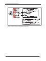
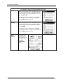
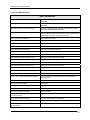
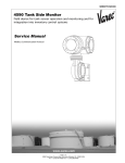
1
MC ToolKit Model MC101 User Manual Release 0 7/03 Doc. No.: 34-ST-25-20 Release: 0 Last Revision Date: 7/03 34-ST-25-20 MC Toolkit User Manual i Notices and Trademarks Copyright 2003 by Honeywell International Inc. Release 0 July, 2003 Warranty/Remedy Honeywell warrants goods of its manufacture as being free of defective materials and faulty workmanship. Contact your local sales office for warranty information. If warranted goods are returned to Honeywell during the period of coverage, Honeywell will repair or replace without charge those items it finds defective. The foregoing is Buyer's sole remedy and is in lieu of all other warranties, expressed or implied, including those of merchantability and fitness for a particular purpose. Specifications may change without notice. The information we supply is believed to be accurate and reliable as of this printing. However, we assume no responsibility for its use. While we provide application assistance personally, through our literature and the Honeywell web site, it is up to the customer to determine the suitability of the product in the application. Industrial Measurement & Control Honeywell 1100 Virginia Drive Fort Washington, PA 19034 Honeywell is a U.S. registered trademark of Honeywell Other brand or product names are trademarks of their respective owners. Page ii 34-ST-25-20 MC Toolkit User Manual Release 0 7/03 About This Document Revision Notes The following list provides notes concerning all revisions of this document. Doc ID Rel ID 34-ST-25-20 Release 0 Date 07/03 Notes First issue of document. Contacts World Wide Web The following lists Honeywell’s World Wide Web sites that will be of interest to our industrial automation and control customers. Honeywell Organization WWW Address (URL/e-mail) Corporate http://www.honeywell.com Industrial Measurement and Control http://content.honeywell.com/imc/ International http://www.honeywell.com/Business/global.asp Field Instruments http://www.field-measurement.com Technical Assistance Center [email protected] (e-mail) Telephone Contact us by telephone at the numbers listed below. Organization Honeywell Inc. Industrial Automation and Control 1-800-343-0228 1-800-525-7439 Technical Assistance Center 1-800-423-9883 Solution Support Center 1-602-313-3578 Asia Pacific Honeywell Asia Pacific Inc. Hong Kong (852) 8298298 Europe Honeywell PACE Brussels, Belgium [32-2] 728-2111 Latin America Honeywell Inc. Sunrise, Florida U.S.A. (305) 364-2355 United States and Canada Release 0 7/03 Phone Number 34-ST-25-20 MC Toolkit User Manual Sales Service iii Symbol definitions The following table lists those symbols used in this document to denote certain conditions. Symbol Definition This CAUTION symbol on the equipment refers the user to the Product Manual for additional information. This symbol appears next to required information in the manual. This WARNING symbol on the equipment refers the user to the Product Manual for additional information. This symbol appears next to required information in the manual. WARNING: risk of electrical shock. This symbol warns the user of a potential shock hazard where HAZARDOUS LIVE voltages greater than 30 Vrms, 42.4 Vpeak, or 60 VDC may be accessible. ATTENTION, Electrostatic Discharge (ESD) hazards. Observe precautions for handling electrostatic sensitive devices Protective Earth (PE) terminal. Provided for connection of the protective earth (green or green/yellow) supply system conductor. Functional earth terminal. Used for non-safety purposes such as noise immunity improvement. NOTE: This connection shall be bonded to protective earth at the source of supply in accordance with national local electrical code requirements. Earth Ground. Functional earth connection. NOTE: This connection shall be bonded to Protective earth at the source of supply in accordance with national and local electrical code requirements. Chassis Ground. Identifies a connection to the chassis or frame of the equipment shall be bonded to Protective Earth at the source of supply in accordance with national and local electrical code requirements. Page iv 34-ST-25-20 MC Toolkit User Manual Release 0 7/03 Contents Introduction ................................................................................................................ 1 Purpose/Scope ....................................................................................................................................1 Product Description .............................................................................................................................2 Procedural Considerations ..................................................................................................................4 Transmitter Type and Communication Mode...................................................................................4 Type of Procedure and Prerequisites ..............................................................................................4 Special Equipment and/or Environment for Calibration...................................................................4 Transmitter/Communications Characteristics......................................................................................5 Honeywell Transmitter (Analog Mode) ............................................................................................5 General Procedures ................................................................................................. 11 Overview............................................................................................................................................11 Headstart on Selected Features of the iPAQ PDA............................................................................11 Start-Up and Basic Operation and Navigation...............................................................................11 Input Methods: Letter, Numbers, Symbols ....................................................................................12 MC Toolkit Display Conventions .......................................................................................................14 Navigation ......................................................................................................................................14 Data Entry and Display ..................................................................................................................16 DE Operating Procedures ........................................................................................ 17 Introduction ........................................................................................................................................17 Summary of Operating Procedures...................................................................................................18 Procedural Considerations ................................................................................................................21 Input calibration..............................................................................................................................21 Output Calibration ..........................................................................................................................21 HART Procedures .................................................................................................... 37 Introduction ........................................................................................................................................37 General Procedures ..........................................................................................................................39 Procedural Considerations ................................................................................................................41 Input Calibration.............................................................................................................................41 Output Calibration ..........................................................................................................................41 Messages and Diagnostic Codes............................................................................. 71 Messages and Diagnostic Codes......................................................................................................71 Reference Data ........................................................................................................ 83 Release 0 7/03 34-ST-25-20 MC Toolkit User Manual v Honeywell DE Fields and Values ......................................................................................................85 Honeywell HART Fields and Values .................................................................................................87 Generic HART Fields and Values .....................................................................................................90 XML Database (Samples) .................................................................................................................97 XML Sample - Honeywell DE.........................................................................................................97 XML Sample - non-Honeywell HART ............................................................................................97 Maintenance............................................................................................................. 99 Modem Battery Replacement............................................................................................................99 MC Toolkit Software Installation/Maintenance ................................................................................100 Overview 100 Replacement Parts ..........................................................................................................................101 Page vi 34-ST-25-20 MC Toolkit User Manual Release 0 7/03 Tables Table 1 DE Displays / Tasks Summary ......................................................................................................................19 Table 2 DE Upload Procedures ..................................................................................................................................22 Table 3 DE Main Menu Procedures ...........................................................................................................................23 Table 4 Input Calibration (DE Transmitters) - Correct Input (Zero), LRV, URV; Reset Corrects ............................26 Table 5 Output Calibration - Loop Test......................................................................................................................31 Table 6 DE Output Calibration - Trim DAC Current .................................................................................................33 Table 7 DE Calibration - Apply Values......................................................................................................................35 Table 8 HART Displays / Tasks Summary.................................................................................................................40 Table 9 HART Device UPLOAD Procedure..............................................................................................................43 Table 10 Honeywell HART Main Menu Procedure ...................................................................................................45 Table 11 Honeywell HART Diagnostics/Service Menu Procedures ..........................................................................48 Table 12 Honeywell HART Calibration - Zero Trim .................................................................................................50 Table 13 Honeywell HART Calibration - LRV and URV..........................................................................................52 Table 14 Honeywell HART Calibration - Reset corrects ...........................................................................................53 Table 15 Honeywell HART Calibration - Loop Test .................................................................................................54 Table 16 Honeywell HART Calibration - D/A Trim..................................................................................................55 Table 17 Honeywell HART Calibration - Apply Values............................................................................................57 Table 18 HART Main Menu Procedures (non-Honeywell Transmitters)...................................................................60 Table 19 HART Diagnostics/Service (non-Honeywell Transmitters) ........................................................................63 Table 20 HART Calibration - Zero Trim (non-Honeywell Transmitter)....................................................................65 Table 21 Calibration - Apply Values (non-Honeywell Transmitter) ..........................................................................66 Table 22 HART Calibration - Loop Test (non-Honeywell Transmitters) ..................................................................68 Table 23 HART Calibration - D/A Trim (non-Honeywell Transmitters) ...................................................................69 Table 24 MC Toolkit Error Messages ........................................................................................................................71 Table 25 DE Messages ...............................................................................................................................................74 Table 26 HART Messages..........................................................................................................................................76 Table 27 ST 3000 Device Status Messages (DE) .......................................................................................................78 Table 28 STT Device Status Messages (DE)..............................................................................................................79 Table 29 ST 3000 Device Status Messages (HART)..................................................................................................80 Table 30 STT Device Status Messages (HART) ........................................................................................................81 Table 31 Glossary.......................................................................................................................................................83 Table 32 DE Fields and Values ..................................................................................................................................85 Table 33 HART Fields and Values.............................................................................................................................87 Table 34 Generic HART Fields and Values ...............................................................................................................90 Table 35 HART Universal Commands.......................................................................................................................95 Table 36 HART Common Practice Commands..........................................................................................................96 Table 37 Battery Removal and Replacement Procedure ............................................................................................99 Table 38 Replacement Parts .....................................................................................................................................101 Release 0 7/03 34-ST-25-20 MC Toolkit User Manual vii Figures Figure 1 Components of the MC Toolkit - w/ Compaq iPAQ......................................................................................1 Figure 2 Components of the MC Toolkit - w/ Symbol 2800 ........................................................................................3 Figure 3 Honeywell ST 3000 Smart Transmitter - Analog mode.................................................................................5 Figure 4 Honeywell Analog Value Scaling ..................................................................................................................7 Figure 5 Honeywell DE Mode Value Scaling ..............................................................................................................9 Figure 6 Honeywell (HART) Transmitter Diagram ......................................................................................................9 Figure 7 HART Point-point and Multi-Drop Value Scaling.......................................................................................10 Figure 8 Start-up - MC Toolkit Application ...............................................................................................................11 Figure 9 Menu Tree - Honeywell DE Displays ..........................................................................................................17 Figure 10 Menu Tree - Honeywell HART Displays...................................................................................................37 Figure 11 Menu Tree: non-Honeywell HART Displays.............................................................................................38 Figure 12 HART Menus (Display Summary).............................................................................................................39 Page viii 34-ST-25-20 MC Toolkit User Manual Release 0 7/03 Introduction Purpose/Scope This manual is intended to facilitate the use of the Honeywell MC Toolkit Model MCT101 communications tool. It is assumed that the user is skilled in the use and maintenance of process transmitters in process control, or that he/she is under direct supervision of others with such skills. The MC toolkit enables communication with several types of smart transmitters (pressure, temperature, etc) that are available for use in the process control industry. The emphasis of the information in this manual is directed primarily on the features and use of the MC Toolkit in performing common maintenance tasks relating to transmitter devices, rather than on the features and installation of specific transmitter devices. It is recommended that that user should have the appropriate manuals available for specific transmitter devices. For background information such as HART communications protocol and network wiring, it is also recommended that the user should obtain publications available from agencies such s the HART Communication Foundation. Figure 1 Components of the MC Toolkit - w/ Compaq iPAQ Release 0 7/03 34-ST-25-20 MC Toolkit User Manual 1 Product Description This manual includes information of two types: · background material that enables a skilled user to select the appropriate procedures in this manual and to apply them in the appropriate sequence, and · detailed descriptions of the MC Toolkit regarding functions, features, and procedures for applying them Product Description The Honeywell MC Toolkit is a handheld communication package that enables convenient and reliable communications with smart transmitters (temperature, pressure, and others) including: · any Honeywell analog transmitter with Honeywell proprietary digital communications protocol or with DE (Digital Enhanced) communications protocol. · any Honeywell transmitters with HART communications protocol · Any HART transmitter from other manufacturers. NOTE: The MC Toolkit supports HART Universal Commands and HART Common Practice Commands for non-Honeywell HART devices. The MC ToolKit includes the following (separately orderable) components: · Page 2 a PDA (Personal Digital Assistant), available in two versions, each with manufacturer's literature - Compaq iPAQ 3830/3850/3870 3950/3970, or - Symbol 2800 (monochrome or color) · a DE/HART Modem that provides an electrical/communications connection between the Pocket PC and the Modem · a Handheld Connector Cable that connects the MC Toolkit to the Modem · Holster for PDA and Modem · Honeywell MC Toolkit application software (CD ROM or 3.5" disks) · Spare Parts (Battery) 34-ST-25-20 MC Toolkit User Manual Release 0 7/03 Introduction Product Description Figure 2 Components of the MC Toolkit - w/ Symbol 2800 Both versions of the PDA incorporate the Microsoft Pocket PC Operating System. Honeywell software operates as an application package in the familiar MS Windows environment, and is virtually identical for both versions of the PDA. In either version, this MC Toolkit application can run simultaneously with other Pocket PC applications. Release 0 7/03 34-ST-25-20 MC Toolkit User Manual 3 Procedural Considerations Procedural Considerations CAUTION! WARNING! In some cases, the use of a field communicator with a transmitter that is connected on-line can have an adverse effect on process operations. Before using the MC Toolkit, be certain that you know the potential consequences of each procedure, and that you use the appropriate safeguards to prevent problems. For example, if the transmitter is an element of a control loop, the loop should be placed in the manual operating mode, and alarms and interlocks ("trips") should be disabled as appropriate before beginning the procedure. The primary factors to be considered are separated into three categories under the following three headings. The information under the following headings is intended as background for use of the DE Procedures and HART Procedures, which are given in separate sections of this manual. Transmitter Type and Communication Mode The MC Toolkit can be used with various types of field transmitters, most of which can be operated in more than one mode. · Honeywell DE transmitter operating in Smart Analog Mode · Honeywell DE transmitter operating in Digital Enhanced (DE) Mode · Honeywell (and other) HART transmitter operating in point-to-point (Analog w/ HART digital mode) · Honeywell (and other) HART transmitter operating in multi-drop (HART-only digital mode) The salient characteristics of each item listed, and the implications of each characteristic in procedures are described under Transmitter/Communications Characteristics Type of Procedure and Prerequisites The MC Toolkit is designed to provide three basic functions: · Monitoring · Configuration · Calibration Depending on combinations of factors such as transmitter type, and communications mode, some procedures such as monitoring the performance of a transmitter can be straightforward and innocuous, but in some cases can also require special preparation and precautions. Special Equipment and/or Environment for Calibration Typically, a smart transmitter delivered by a major manufacturer today is designed to provide a high degree of precision throughout its operating range, and has been calibrated to a high level of accuracy that is not easy to duplicate in the user's plant process areas. Moreover, the design, materials, and manufacturing process employed will ensure that the instrument will stay within calibration limits for an extended period. Typically, calibration of a process-connected transmitter will degrade, rather than augment, the capability of a smart transmitter. For this reason, the calibration procedures in this MC Toolkit User Manual include a recommendation that the transmitter is removed from service and is calibrated only in a controlled laboratory environment, using equipment whose precision is certified. Page 4 34-ST-25-20 MC Toolkit User Manual Release 0 7/03 Introduction Transmitter/Communications Characteristics Transmitter/Communications Characteristics The characteristics of a typical Honeywell Smart Pressure Transmitter are summarized in Figure 3 through Figure 7, following. Honeywell Transmitter (Analog Mode) Analog-to-Digital Sensing As indicated by key number ¬ in Figure 3, the sensor is a sealed assembly that typically includes three separate sensors: Differential Pressure (DP), Static Pressure (SP) and Temperature (Temp). Input Characterization The sensor also includes a PROM, , which is Non-Volatile Memory (NVM) that stores "characterization" constants written at the factory, and calibration constants, which can be written at the factory and/or at the user's site. The data in NVM is used in an algorithm in the microprocessor, ®, which is executed continuously to calculate the input value. Figure 3 Honeywell ST 3000 Smart Transmitter - Analog mode The characterization constants, which are written at the factory, are derived from highly precise testing of the sensor's response over a range of temperatures, and from the Lower Range Limit (LRL) to the Upper Range Limit (URL) of the sensor. The purpose of the characterization constants is to compensate for very small inaccuracies in the sensor that are introduced by variations inherent in construction materials, and to ensure that the calculated input is a high-fidelity representation of the analog input (linear or square root), with a precise "zero" reference. Input Calibration ("Corrects") To optimize accuracy, the PROM includes storage for calibration constants: Correct Input Zero, Correct LRV, and Correct URV. The corrects constants provide for optimum accuracy in that they enable fine-tuning of the input calculations, by first correcting at zero input, then bounding the input calculations at the user's operating Release 0 7/03 34-ST-25-20 MC Toolkit User Manual 5 Transmitter/Communications Characteristics range. That is, corrections are applied at the Lower Range Value (LRV) and the Upper Range Value (URV). Factory calibration can be specified in the purchase order. Also, if precision equipment, suitable environment, and required skill are available at the user's site, input calibration can be done locally. Reset Corrects In some cases, the calibration procedure yields unsatisfactory results such that the Corrects constants must be removed from memory. The Reset Corrects erases all three corrects constants, so that only the factorywritten characterization constants will be retained in the PROM. Digital Communication Path As indicated at key number ¯ in Figure 4, the Honeywell Smart Transmitter includes a path for digital communications between the sensor (via the microprocessor) and the 4-20 mA current loop that connects the transmitter to external communications devices such as process control equipment ("receiver") and/or to a MC Toolkit. Digital to-Analog Conversion and Transfer The digital-to-analog converter (D/A) shown at key number ° in Figure 3 is shown as a box with a dotted line to indicate that analog output mode is a user-selectable feature, for use in an application whose receiving equipment requires an analog input. Note that the Digital I/O (Comm) (communications) box is shown in Figure 3 with solid line to indicate that the digital communications path is available at all times, even when analog mode is selected. Honeywell Transmitter Output - Analog Mode The diagram in Figure 4 provides an overview of a Honeywell transmitter operating in the analog mode. Analog (PV Signal) Output The vertical scale at the left of Figure 4 is an example of the available range (LRL to URL) of a pressure transmitter sensor as built and characterized at the factory. The area of this scale that is highlighted in white represents the configured process operating range (LRV to URV) - in this case, from 100 in H2O to 225 in H2O. Note that Engineering Units (EUs) shown in Figure 4 are included here only for reference. The transmitter does not perform any conversion of the base units value to Engineering Units. All conversion to EUs is performed in the MC Toolkit and/or in other receiving devices such as operating panels associated with control equipment. Default conversion is to inches-H2O @39F.) The output of a Honeywell transmitter operating in the analog mode is a scaled value (0% - 100%) of current (4 mA to 20 mA), whose lower and upper limits correspond to the configured operating range (LRV-URV), respectively. At the right of Figure 4, "PVEULO", "PV", and "PVEUHI" are examples of parameter names that appear on Honeywell control equipment, which are used as follows. Page 6 Parameter Name Parameter Description Display Examples PVEULO Process Value , Engineering Units, Low PVEULO 100 in H20 PV Process Value PV 175 in H20 PVEUHI Process Value , Engineering Units, Low PVEUHI 225 in H20 34-ST-25-20 MC Toolkit User Manual Release 0 7/03 Introduction Transmitter/Communications Characteristics Figure 4 Honeywell Analog Value Scaling Digital (Communications Signal) Input/Output As indicated at the right of Figure 4, communications between the MC Toolkit and the Honeywell Smart Transmitter consist of digital pulse strings, with rapid transitions of current level between (approximately) 4 mA and 20 mA. Caution: These rapid transitions provide for effective communications, but will interfere adversely with a transmitter operating on-line in a control loop. The MC Toolkit communicates digitally; exercise caution and good judgement when connecting the unit to an on-line transmitter operating in the analog mode. Honeywell Transmitter Output - Digital Enhanced Mode Most of the operation of the Honeywell Smart Pressure Transmitter Digital Enhanced (DE) mode is similar to that of operation in the analog mode. The essential characteristics of operation in DE mode are shown in Figure 5. As indicated at the right of Figure 5, output values of process variables, as well as digital communications, are transferred to a receiving device digitally. The digital coding is Honeywell proprietary, which requires the use of DE-capable Honeywell control equipment. The use of DE mode offers several advantages: Release 0 7/03 process safety Unlike in the analog mode, communications devices do not "bump" the value of the PV. accuracy is retained with less maintenance Digital communications are relatively immune to small variations in circuit resistance or supply voltage. facilitates maintenance tasks Honeywell control systems include operating displays that enable direct communication with transmitters operating in DE mode. 34-ST-25-20 MC Toolkit User Manual 7 Transmitter/Communications Characteristics CAUTION: Although it in not necessary to put a control loop in manual before communicating with a transmitter operating in DE mode, caution is required if there is any potential for error in identifying operating mode. Honeywell HART Transmitters Transmitters with HART capability have features that vary among manufacturers and with the characteristics of specific devices. The MC Toolkit supports the HART Universal, Common Practice, and Device Specific Commands that are implemented in Honeywell HART transmitters. As the diagram in Figure 6 shows, the Honeywell HART Transmitter is virtually identical to non-HART transmitters, except that the HART version includes a Digital I/O Modulator/Demodulator block (key number ¯ ) instead of the Honeywell DE communications block. As indicated in Figure 7, the output of the HART includes two primary modes: · Point-to-Point Mode, in which one transmitter is connected via a two-conductor, 4-20 mA current loop to one receiver. · Multi-Drop Mode, in which several transmitters are connected via a two-conductor network to a multiplexed receiver device. In point-to-point mode, the value of the primary PV is represented by a 4-20 mA current loop, almost identical to that of the Honeywell Transmitter operating in analog mode. In this case however, the analog signal is modulated by Frequency Shift Keying (FSK) methods, using frequencies and a current amplitude that do not affect analog sensing at the receiver. Note that the accuracy of the analog level must be precisely controlled for accurate sensing, but that HART communications will not "bump" the process variables. In multi-drop mode, up to 16 transmitters (addresses 0-15) can exist on the two-conductor network, which precludes analog transmission methods. In this case, the same FSK modulation method is used for conveying levels of PV (and other variables) and also for communications. CAUTION: Before connecting to a HART transmitter, ensure that the MC Toolkit is not set up for DE communications, whose current amplitude can "bump" process variables in either point-topoint mode or in multi-drop mode. Other HART Transmitters HART-capable transmitters from any manufacturer and for any specific purpose are designed to commonagreement standards that provide for inter-operability. Guidelines published by the HART Communication Foundation enables manufacturers to design devices that communicate via a set of standard commands and responses. The standard set of commands is an integral component of the Honeywell MC Toolkit that enables communication with many HART transmitters from other manufacturers. The MC Toolkit supports the HART Revision 5.0 Universal Commands and HART Revision 5.0 Common Practice Commands. However, the MC Toolkit supports only a recommended number of Common Practice commands. The MC Toolkit does not support device-specific commands for non-Honeywell transmitters. For more information, refer to tables in the Reference Data section of this manual. Page 8 34-ST-25-20 MC Toolkit User Manual Release 0 7/03 Introduction Transmitter/Communications Characteristics Figure 5 Honeywell DE Mode Value Scaling Figure 6 Honeywell (HART) Transmitter Diagram Release 0 7/03 34-ST-25-20 MC Toolkit User Manual 9 Transmitter/Communications Characteristics Figure 7 HART Point-point and Multi-Drop Value Scaling Page 10 34-ST-25-20 MC Toolkit User Manual Release 0 7/03 General Procedures Overview The MC Toolkit includes Honeywell MC Toolkit software running in the PDA, a general-purpose, handheld computing device. This section highlights some of the general-purpose features that facilitate use of the MC Toolkit software. Headstart on Selected Features of the iPAQ PDA The following is intended as a primer for using selected Pocket PC features with the MC Toolkit application. Each of the following descriptions of features includes only the name of the feature and its functionality as it is used with the MC Toolkit. The details of each feature are provided in the HELP information that is included with the PDA. As you become familiar with the MC Toolkit, you may want to explore other features that are listed and described in the PDA HELP information. Start-Up and Basic Operation and Navigation The sequence for starting the Pocket PC and the MC Toolkit operation is illustrated in Figure 8 Start-up MC Toolkit Application. Figure 8 Start-up - MC Toolkit Application Release 0 7/03 34-ST-25-20 MC Toolkit User Manual 11 Headstart on Selected Features of the iPAQ PDA Input Methods: Letter, Numbers, Symbols The PDA includes four methods for character input: Block Recognizer, Keyboard, Letter Recognizer, and Transcriber. In the Keyboard method, the user selects a text field in display, and then selects a character at a time from a virtual keyboard. Using the keyboard involves familiar concepts that will enable quick and accurate entries. In the other three methods, the stylus is used to write the desired input directly onto the screen, and each requires some adaptation of user skills. Of these, the Transcriber is probably the most efficient and easiest to use. Input Methods: Selections and Options (Examples) Overview Display - Input Selection Display - Input Options Display - Input Selection Display - Input Options To select an input method, tap the at the lower-right of arrow the display, then tap the name of the desired input method. To select an option for the selected input method, select Settings from the Start Menu, Input from the Settings menu, and then select the desired input options. Note that the icon next to the selection arrow changes with the method selected. Block Recognizer Overview In the Block recognizer, the stylus is used to write characters into a letter pad (the box at bottom, on the left) or a numeric pad (on the right). The "?" icon is a link to HELP; the @$ icon is a link to a table of symbols. Page 12 34-ST-25-20 MC Toolkit User Manual Release 0 7/03 General Procedures Headstart on Selected Features of the iPAQ PDA Letter Recognizer Overview Empty Text Input Port Completing Entry Display - Input Selection Display - Input Options In the Letter Recognizer method, characters are simply selected from a virtual QWERTY keyboard. As indicated at right, options include small keys or large keys. Short-cut options such as "gestures" (stylus motion on the screen) and others are also available via the Settings menu. Transcriber Overview Transcriber facilitates entry of text in letters, numbers, and entire words. Extensive HELP is provided for very handy features. Release 0 7/03 34-ST-25-20 MC Toolkit User Manual 13 MC Toolkit Display Conventions MC Toolkit Display Conventions Navigation Menu Buttons In general, selecting a button in a display will call up the next-lower-level display, whose title is the same or similar to the label on the button. A menu tree for Honeywell DE Displays is given Figure 9, and a menu tree for HART display is given in Figure 10. Back Button In general, selecting the Back button at the bottom of any display will call up the next-higher-level (previous) display. In most displays, the Back button is at bottom-right or bottom-center. When it appears at bottom-left, along with a left-pointing arrow, it indicates that selecting the Back button will necessitate a new Upload of data from the transmitter to the MC Toolkit (~ 60 seconds). Menu Bar Menu Bar, Menu Selections, and HELP display Menu selections The menu bar, at the bottom of each display, enables the user to perform file, diagnostic, and utility functions. A typical display is shown below. Menu selections are shown in detail at right Page 14 34-ST-25-20 MC Toolkit User Manual Release 0 7/03 General Procedures MC Toolkit Display Conventions Menu Bar, Menu Selections, and HELP display File Exit Closes the MC Toolkit application To export an XML file, select File, Export. A popup message appears. Export Select the OK button. Enables export of database parameters in XML format, which can be used by other programs such as DocuMint. (Refer to the Reference Data section for more information.) The Export selection is not available until a transmitter database has been uploaded. Modem Diagnostics In DE Mode, the Connection State may be: · Analog · 4 Byte DE · 6 Byte DE In HART mode, the Connection State may be: · Burst Mode · Not in Burst Mode HELP display The Help display is available whenever the MC Toolkit is active. It includes three groups of topics, each of Selectable from the Help Menu - General - DE - HART Each group includes a list of topics. Each topic (in blue, underlined letters) is selectable to provide direct access to the Help information. Dragging the cursor in the scrollbar at right enables viewing of all three groups of topics. At the bottom of each group, a Back to Top selection moves the display to the beginning of the first group of topics. Teh Note: The View, Find and (arrows) selections at the bottom of the screen apply to the Help that applies to the Pocket PC, and not to the MC Toolkit application. Release 0 7/03 34-ST-25-20 MC Toolkit User Manual 15 MC Toolkit Display Conventions Data Entry and Display Key number / Description Illustration: Key Numbers 1. Box with no arrow and with gray background indicates a readonly (R/ ) field. Numeric or text values in transmitter are displayed only; user entry or modification is not permitted. 2. Box with white background and with no arrow indicates Read/Write (R/W) text or numeric input field. Values previously stored in memory (of the transmitter or of the MC Toolkit) are displayed. The user can enter or modify values using an appropriate Input Method (e.g., Keyboard). Entering a new value turns the background yellow, indicating that the value in the box is different from the value in memory. When the Send button (6) is selected, the value in the box is copied to memory in the transmitter, and the background color returns to white. If the user exits the screen before using the Send button, the changes will be ignored. 3. Box with white background and arrow at right indicates a read/write (R/W) selection list. The value previously selected and stored in memory is displayed. Selecting the arrow at right presents a list of available selections, and selecting an item from the list places it in the selection box. If the user exits the screen before using the Send button, the changes will be ignored. 4. The label above the box indicates the meaning of the data inside the box. 5. The Back button at the bottom of the display causes the display that was viewed previously to return the screen. 6. The Send button is at half intensity when no values have been changed. It changes to full intensity when one or more of the boxes contain a changed value. Selecting the Send button when it is highlighted will copy all changed values to memory, and the button will return to half-intensity. Page 16 34-ST-25-20 MC Toolkit User Manual Release 0 7/03 DE Operating Procedures Introduction DE Operating Procedures Introduction This section contains procedures for using the MC Toolkit to communicate with Honeywell DE Transmitters. For specific data relating to parameters involved in the procedures, refer to Reference Data. Figure 9 Menu Tree - Honeywell DE Displays Release 0 7/03 34-ST-25-20 MC Toolkit User Manual 17 Summary of Operating Procedures Summary of Operating Procedures To access displays for Honeywell DE Transmitters: Page 18 · Start the MC Toolkit application; the CONNECT TO ... display will appear. (Refer to Figure 8 Start-up - MC Toolkit Application.) · Upload the database from the transmitter. (The QUICK MONITOR display will enable viewing of key parameters before taking the time for database uploading.) The DE MAIN MENU appears. (Refer to Figure 9 Menu Tree - Honeywell DE Displays in this section.) · Select the appropriate display from the DE MAIN MENU. (Refer to 34-ST-25-20 MC Toolkit User Manual Release 0 7/03 DE Operating Procedures Summary of Operating Procedures Table 3 DE Main Menu Procedures in this section, and to the list of DE displays .) The content of each display is summarized in Table 1. Table 1 DE Displays / Tasks Summary Menu Item DEVICE INFO GENERAL DE CONFIGURE CALIBRATION LOCAL METER Release 0 7/03 Enter: Device Type: · Tag ID · Message (in Scratch Pad) Select: · PV Type Enter: · Comm Mode · Line Filter (STT) · T/C Fault Detect (STT) Select: · PV Units · SV Units · Conformity (ST) · Damping · Sensor Type (STT) · Linear Enter: · LRV · URV Enter/Select: · Correct Input (Zero) · Correct Input (LRV) · Correct Input (URV) · Reset Corrects (Zero, LRV, URV) · Loop Test (Check · Trim DAC Current (Calibrate output current) · Apply Values (that is, re-range LRV and URV to PV input) Task Observe (Read): · Type · Serial Number · Firmware Version Observe (Read): · Failsafe Direction Select: · Meter Units (EU) Enter: · Custom Units · (Custom) Flow (EU) value: Upper, Lower 34-ST-25-20 MC Toolkit User Manual Observe (Read): · LRL · URL · Span · Sensor Type (ST) Observe (Read): · Input at Zero, LRV, and URV · (Verify) Reset Corrects · · Loop Current (continuity) Output Current level (at 0 %, 100%) Applied values of LRV and URV · Observe (Read): · Meter Hardware Type · 19 Summary of Operating Procedures Menu Item MONITOR Auxiliary Configuration (STT 3000) Page 20 Select: · Critical Status Latching · Write Protection · NAMUR · CJ Compensation Enter: · CJ Temp · Password (Write Protection) · New Password 34-ST-25-20 MC Toolkit User Manual Task Observe (Read): · Input value · Output value · Secondary (Input) value · Gross Status (code) · Device Status (Messages) Observe (Read): · High/Low PV Values Release 0 7/03 DE Operating Procedures Procedural Considerations Procedural Considerations Input calibration Input calibration of pressure transmitters should be done only when necessary, and should be done only under conditions that will ensure accuracy: · The transmitter should be taken out of service, and should be moved to an area with favorable environmental conditions: clean, dry, and temperature-controlled. · The source for the input pressure must be very precise, and certified for correct operation. · The procedures should be done by qualified personnel. Details of requirements and procedure are given in Table 4. Output Calibration The Loop Test procedure is intended as a check for continuity and condition of components in the output current loop. The Loop Test procedure is given in Table 5. The Trim DAC Current procedure calibrates the output of the Digital to Analog converter for minimum (0%) and maximum (100%) values of 4 mA and 20 mA, respectively. This procedure is used for transmitters operating on-line in analog mode, to ensure proper operation of the transmitter with all associated circuit components (wiring, power supply, control equipment, etc). It is necessary to use precision test equipment (an ammeter or a voltmeter in parallel with precision resistor). The Trim DAC procedure is given in Table 6. The Apply Values procedure uses actual Process Variable input levels for calibrating the range of a transmitter. To measure a liquid level for example, a sight-glass can be used to determine the minimum (0%) and maximum (100%) level in a vessel. The Process Variable is carefully adjusted to stable minimum and maximum levels, and the LRV and URV values are then set by commands from the MC Toolkit. The DE Apply Values procedure is given in Table 7. Release 0 7/03 34-ST-25-20 MC Toolkit User Manual 21 Procedural Considerations Table 2 DE Upload Procedures DE Upload Procedures Select the DE Device button This Warning message appears. If the MC Toolkit is connected to a DE Device, select the OK button. Select the Upload button; the wait cursor and progress bar appear. Note: This Warning appears only if the transmitter is configured for operation in analog mode. Use this display to - - WARNING! Before proceeding, if the transmitter is part of a control loop, ensure that interlocks and alarms are secured and that the loop is in Manual control. Verify device identification and to monitor Gross Status process conditions Then, the Main Menu for an ST 3000 Transmitter appears. Select the desired Units for the Process Variable input using the PV Units drop-down list. Then, select the OK button in the popup message. The display at right appears. Page 22 34-ST-25-20 MC Toolkit User Manual Release 0 7/03 DE Operating Procedures Procedural Considerations Table 3 DE Main Menu Procedures DE Main Menu (ST 3000) Note: This message appears if the <Back button is selected if the transmitter was set to Output Mode (in Calibration procedures), and the Output was not later cleared. Device Info General DE Main Menu Procedures (STT 3000) (ST 3000) Tag ID (r/w) User ID up to 8 alphanumeric characters (suggestion: relate to functional process entities and/or plant areas). Type (r) Manufacturer's device type identifier (typically, a model number) Firmware Version (r) Manufacturer's Firmware version identifier Serial Number (r) Manufacturer Scratch Pad (r/w) Up to 32 alphanumeric characters (suggestion: messages to control room regarding observed/assigned operational status) (STT 3000) PV Type (r/w) Select: Dual Range (STDC) or Single Range or Single Range w/SV Communication Mode (r/w) Select: Analog or DE 4 Byte or DE 6 Byte FS Direction (r) (Upscale or Downscale; selection is jumpered in the transmitter). Line Filter (r) Select: 50hz or 60hz. T/C Fault Detect (r/w): Select: Enabled or Disabled. Release 0 7/03 34-ST-25-20 MC Toolkit User Manual 23 Procedural Considerations DE Main Menu Procedures DE Configure ST 3000 LRL (r): Lower Range Limit URL (r): Upper Range Limit LRV (r/w): Lower Range Value URV (r/w): Upper Range Value PV Units (r/w) Selection of scaling value (default: inches of H2O@39) SV Units (r/w) Selection of scaling value (0C/0F) Sensor Type (r) Sensor Type associated with the transmitter Damping (r/w) STT 3000 Selection of level of digital noise reduction Span (r) Process Range (URL - LRL) Conformity (r/w) (ST 3000) Selection of conformity to input form: Linear or Square Root Linearization (r/w) (STT 3000) Selection of conformity to input form: Linear or Non Linear Calibration For more information, refer to: Table 4, Table 5, Table 6, Table 7. Meter Hardware (r) Type designation of meter associated with the transmitter Meter Units (r/w) Selection EUs for Local Meter Custom Units (r/w) (Refer to Transmitter User Manual). Flow EU Upper Value (r/w) Selection of standard Engineering Units for Flow Upper Value Flow EU Lower Value (r/w) Selection of standard Engineering Units for Flow Lower Value Local Meter (ST 3000) Page 24 34-ST-25-20 MC Toolkit User Manual Release 0 7/03 DE Operating Procedures Procedural Considerations DE Main Menu Procedures Local Meter (ST 3000 example) Critical Status Latching Select Enabled or Disabled. Auxiliary Configure NAMUR Select Enabled or Disabled. Select the Read button to display the lowest and the highest PV values since last read. (Disable requires that Write Protect is set to Not Write Protected.) CJ Temp. Enter External Cold Junction Temperature. Select the Read HI/LO button to call up the READ HIGH/LOW PV display. Monitor SV (r) Secondary Variable in Engineering Units Gross Status (r) Gross transmitter status. Select the Device Status button to call up the Device Status display. Communication Status (r) Input (r) Sensor input in Engineering Units Output (r) Loop output as percent of Span Release 0 7/03 For status information, refer to the section on Messages and Diagnostic Codes. 34-ST-25-20 MC Toolkit User Manual 25 Procedural Considerations Table 4 Input Calibration (DE Transmitters) - Correct Input (Zero), LRV, URV; Reset Corrects Input Calibration (De Transmitters) - Correct Input (Zero), LRV, URV; Reset Corrects Requirements: Objective(s): · Using a precision PV input source as a reference, command the transmitter to write calibration coefficients to NonVolatile Memory associated with transmitter input hardware and software. Input source, with accuracy of at least 0.04% · resistor, at least 250-ohms · Voltmeter or Ammeter · 24 Vdc Power Supply (nominal) · · Clean work area with suitable environmental conditions. · Correct Input (Zero) · Correct LRV · Correct URV Pressure Transmitter must be level. Overview of Procedures: The Zero-Correct procedure establishes the correct vertical positioning of the response profile. The LRV Correct and URV Correct procedures establish the correct slope of the response profile in the process operating range by rotating the response profile around the zero-reference point as a pivot. The Zero-Correct procedure can be done at any time during the Correct LRV and Correct URV procedures in the same calibration session. The Correct LRV and Correct URV procedure should never be performed without first performing the Correct Input (Zero) procedure in the same calibration session. Page 26 34-ST-25-20 MC Toolkit User Manual Release 0 7/03 DE Operating Procedures Procedural Considerations Input Calibration (De Transmitters) - Correct Input (Zero), LRV, URV; Reset Corrects Set-Up On Bench A typical bench set-up is shown at right. Connect the MC Toolkit as indicated, and establish communication with the transmitter. For these procedures, components in the current loop are not critical, provided that they support reliable communication between the transmitter and the MC Toolkit. If a Honeywell ST 3000 Pressure Transmitter is being calibrated, positioning (leveling) is important, because the meter body contains fluids that can affect zero sensing. Enter (configure) From the DE MAIN MENU, select Configure to call up the DE CONFIGURE display. values for LRV and URV a. Use the PV Units to select the appropriate Engineering Units. b. Using the keyboard, enter the desired LRV and URV values. c. Select the Send button to copy all newly entered values to the transmitter. When the copy operation is complete, Send will be displayed in half intensity. Release 0 7/03 34-ST-25-20 MC Toolkit User Manual 27 Procedural Considerations Input Calibration (De Transmitters) - Correct Input (Zero), LRV, URV; Reset Corrects Call up Calibration display Navigate to the DE Calibration display as follows. Select Back (go to DE Main Menu), then select the Calibration button. Correct Input at Zero Select Corr. Input (zero). This message appears. As indicated below, this procedure will shift the slope up or down to eliminate the error at the zero reference. The slope (angle) of the response is unchanged. NOTE: The PV Input (Zero) refers to a known standard such as zero pressure (e.g.: vent both sides of a DP transmitter). Select Yes in the message box above; this message appears. ` At this point, ensure that the value of the PV applied at the input is exactly Zero. Then, select the OK button in the popup message. This action sends the Correct Input (Zero) command to the transmitter, which adjusts the input calculation. Wait until this message appears. Page 28 When the transmitter has completed the Zero Correction, this message appears. 34-ST-25-20 MC Toolkit User Manual Select the OK button to acknowledge. Release 0 7/03 DE Operating Procedures Procedural Considerations Input Calibration (De Transmitters) - Correct Input (Zero), LRV, URV; Reset Corrects Correct Input at LRV Select the Correct LRV button. This message appears. Select the OK button; this message appears. (ST 3000) Adjust the PV input pressure to the exact value of the LRV entered in the DE CONFIGURE display. Correct Input at LRV Select the Correct LRV button. This message appears. (STT 3000) Observe the input pressure at the applied value; when it is stable, select the OK button. Adjust the input temperature to the exact value of the LRV entered in the DE CONFIGURE display. When the transmitter has completed the LRV correction, this message appears. Select OK to acknowledge. Select the OK button; this message appears. Select the OK button to acknowledge Correct Input at URV Select the Correct URV button. This message appears. (ST 3000) Correct Input at URV (STT 3000) Select the Correct URV button. This message appears. Adjust the PV input pressure to the exact value of the URV entered in the DE CONFIGURE display. When the transmitter has completed the URV correction, this message appears. Select the OK button. Select OK to acknowledge. Adjust the input temperature to the exact value of the URV entered in the DE CONFIGURE display. Select the OK button; this message appears. Select the OK button to acknowledge Release 0 7/03 34-ST-25-20 MC Toolkit User Manual 29 Procedural Considerations Input Calibration (De Transmitters) - Correct Input (Zero), LRV, URV; Reset Corrects Reset Corrects Note: This function commands the transmitter to overwrite all user input corrections with factory default ("characterization") values. If corrects should not be overwritten with factory values, select the No button. If corrects need to be overwritten, select the Yes button. The timer will appear briefly, indicating the operation is performed. It is intended for use only when excessive corrections render the transmitter inaccurate. Page 30 34-ST-25-20 MC Toolkit User Manual Release 0 7/03 DE Operating Procedures Procedural Considerations Table 5 Output Calibration - Loop Test Output Calibration - Loop Test Objective Verify the integrity of electrical components in the output current loop. Connect the MC Toolkit as indicated, and establish communication with the transmitter. For these procedures, values of components in the current loop are not critical, provided that they support reliable communication between the transmitter and the MC Toolkit. Loop Test In the Output Calibration box, select the Loop Test button; the display at right appears. Select the Set button. Select the desired constant-level Output: 0 %, 100 %, or Other (any of 0 % - 100 %). Note: If the transmitter is in Analog mode, you can observe the output on an externally connected meter or on a Local Meter. Select the Yes button, and observe the output current at 0%, 100%, or Other (userentered) %. To view the Monitor display, navigate Back from the LOOP TEST display and select the MONITOR display. Example: DE output (100 %), as viewed on the MC Toolkit. This popup appears; select Yes to continue. In DE Mode, the output can be observed on the Local Meter or on the Monitor display on the MC Toolkit. Release 0 7/03 34-ST-25-20 MC Toolkit User Manual 31 Procedural Considerations Output Calibration - Loop Test Example The displays at right illustrate a Set Output selection and setting of Other, at 57 %. Caution: !! Unintended exit in Output Mode? !! Page 32 If Yes was selected as above in the CONFIRM! popup message, it is possible to exit MC Toolkit application while the Output is fixed at constant current. This message at right appears if the user performs an operation on the MC Toolkit that will terminate the connection to the transmitter while the transmitter is in output mode. 34-ST-25-20 MC Toolkit User Manual Select Yes button only if constant-current Output with the MC Toolkit is intended. Otherwise, select the No button, go back to the LOOP TEST display, and select the Clear Output button. Release 0 7/03 DE Operating Procedures Procedural Considerations Table 6 DE Output Calibration - Trim DAC Current DE Output Calibration - Trim DAC Current Overview of Objectives For a DE transmitter operating in analog mode in a user's application, calibrate the analog output current to the PV input range. That is, adjust the output such that 4 mA corresponds to 0% (LRV), and 20 mA corresponds to 100% (URV). Call up display In the DE MAIN MENU, select the Calibration button. Select the Trim DAC Curr. button; this display appears. The CALIBRATION menu appears. Release 0 7/03 34-ST-25-20 MC Toolkit User Manual 33 Procedural Considerations DE Output Calibration - Trim DAC Current Trim Output Current Select the Set Output To 0% button or the 100% button. The message popup at right appears. Caution: In Output Mode, output current is fixed at 0% or 100%. Ensure that the loop is in Manual control. Select the Yes button, and at the meter, observe the level of loop current. NOTE: On the voltmeter, 4 mA corresponds to 1 volt. Using the MC Toolkit, adjust the loop current to the Zero Percent level (4 mA). If the current is low, tap the Increment button; if it is high, tap the Decrement button, and observe the change on the meter. NOTE: If the error is large, you can accelerate the adjustment rate by changing the Step Size to 10 or to 100. When the zero current level (4 mA) is achieved, select the Set Output To 100 % button. NOTE: On the voltmeter, 20 mA corresponds to 5 volts. Use the Increment and/or Decrement buttons to adjust the output current to 20 mA. When the 100% current level (20 mA) is achieved, select the Clear Output button. (Note that the button changes to half intensity.) ? Change display while in Output Mode If you select the Back button before selecting the Clear Output button, the display at right will appear. If you are sure that you want to remain in Output Mode while viewing other displays, select the Yes button; otherwise, select the No button, and the Clear Output button ? Page 34 34-ST-25-20 MC Toolkit User Manual Release 0 7/03 DE Operating Procedures Procedural Considerations Table 7 DE Calibration - Apply Values De Calibration - Apply PV values to Set LRV and Set URV Overview · Manually set the Process Variable input to 0%, and apply this value to Set LRV; of · Manually set the Process Variable input to 100%, and apply this value to Set URV. Objectives: NOTE: This procedure applies to DE Transmitters operating in DE Mode as well as to those operating in Analog (current) Mode. On the DE MAIN MENU, select the Calibration button. In the Apply Values group, select the Set LRV button. The popup message at right appears. Note: The value of the Input indicated in this message updates only when the popup message is called up. To update this value, select the No button, and again select the Set LRV button in the CALIBRATION display. Release 0 7/03 34-ST-25-20 MC Toolkit User Manual 35 Procedural Considerations De Calibration - Apply PV values to Set LRV and Set URV Set LRV While observing the PV value at the physical process element, (using a sight glass, for example) adjust the Process Variable to the desired Minimum (0 %) level, then select Set LRV If the displayed value is satisfactory, select Yes to copy the Input Value to the LRV in the transmitter. If not, select NO and repeat this step. Set URV While observing the PV value at the physical process element, (using a sight glass, for example) adjust the process variable to the desired Maximum level, then select Set URV. If the displayed value is satisfactory, select Yes to copy the Input Value to the URV in the transmitter. If not, select NO and repeat this step. Verify settings Page 36 The results of the Set LRV and Set URV actions can be verified by calling up the DE CONFIGURE display. 34-ST-25-20 MC Toolkit User Manual Release 0 7/03 Introduction HART Procedures Introduction This section contains procedures for using the MC Toolkit to communicate with Honeywell and nonHoneywell Transmitters with HART communications protocol. In some cases, the Honeywell transmitters differ somewhat from non-Honeywell transmitters, separate procedures are provided as appropriate. For specific data relating to parameters involved in the procedures, refer to Reference Data. Figure 10 Menu Tree - Honeywell HART Displays Release 0 7/03 34-ST-25-20 MC Toolkit User Manual 37 Introduction Figure 11 Menu Tree: non-Honeywell HART Displays Page 38 34-ST-25-20 MC Toolkit User Manual Release 0 7/03 HART Procedures General Procedures Honeywell HART Transmitters Other HART Transmitters Figure 12 HART Menus (Display Summary) General Procedures To access displays for HART Transmitters: · Start the MC Toolkit application; the CONNECT TO ... display will appear. (Refer to Figure 8 Start-up - MC Toolkit Application). · Upload the database from the transmitter. (Refer to Table 9 in this section.) · - (The QUICK MONITOR display will enable viewing of key parameters before beginning other procedures.) - The HART MAIN MENU appears. Select the appropriate display from the HART MAIN MENU. (Refer to Table 10 Honeywell HART Main Menu Procedure in this section, and to the following task list.) NOTE: Although some of the MC Toolkit displays (and procedures) for Honeywell transmitters differ from those for non-Honeywell transmitters, the MC toolkit automatically provides the appropriate displays. Although the user is not required to make any selections in the displays, he must be aware of transmitter type to select the appropriate procedures in this manual. Release 0 7/03 34-ST-25-20 MC Toolkit User Manual 39 General Procedures Table 8 HART Displays / Tasks Summary Menu Item DEVICE INFO BASIC SETUP OUTPUT CONDITION ALARM (STT 3000) DIAGNOSTICS /SERVICE CALIBRATION Local Meter (ST 3000 only) Sensor (STT 3000) Page 40 Task Enter: Observe (Read): Device Type: · Model · Tag ID · Device ID · Message · Manufacturer · Descriptor Enter: Observe (Read): · LRV · LRL · URV · URL Select: · Sensor Type · PV Sensor Units · Damping (Time) · SV units · Transfer Function (ST 3000) Select: Observe (Read): · Poll Adrs (0-15) · PV Output · Scaled D/A Trim (Output · Alarm Direction Calibration procedure) · Requested Preambles · NAMUR (STT 3000) Select: · Break Detect · Latching Alarm · Clear Latching Select (Procedure): · Master Reset · Device Status · Monitor (Output: mA, %; PV Output, SV) · Write Protect (Enter/Change Password) Select (Procedure): Input Calibration · Zero Trim · Correct Input LRV · Correct Input URV · Reset Corrects Output Calibration · Loop Test · D/A Trim Input (Re-Range to PV) · Apply Values (LRV, URV) Select: Observe (Read): · Meter Units (EU) · Meter Type Enter: · Custom Units (conversion constant) · (Custom) EU Flow: Low/High Select: · Sensor Type · Line (AC ) Filter · CJ Compensation · 34-ST-25-20 MC Toolkit User Manual Observe (Read): · RTD Wire Selection Release 0 7/03 HART Procedures Procedural Considerations Menu Item EXTENDED INFO DYNAMIC VARS BURST MODE SPEC. MONITOR Task Observe (Read): · Universal Rev. · Software Rev. · Field Device Rev. · Poll Address · PROM ID · # Req. Preams · PV Sensor S/N · Final Assembly # Enter: · Primary Variable Code · Secondary Variable Code · Tertiary Variable Code · Quaternary variable Code Select: · Burst Mode · Burst Options Select: · No. of Var's Query · Device variable Observe (Read)_: · Values of selected variables Procedural Considerations The details of procedures vary with device type. This section contains a set of procedures for Honeywell HART Transmitters, and separate set of procedures for non-Honeywell HART devices. Input Calibration Input calibration of transmitters should be done only when necessary, and should be done only under conditions that will ensure accuracy: · The transmitter should be taken out of service, and should be moved to an area with favorable environmental conditions: clean, dry, and temperature-controlled. · The source for the input pressure must be very precise, and must be certified for correct operation. · The procedures should be done by qualified personnel. For Honeywell HART devices, input calibration procedures are given in Table 12 through Table 14, and for non-Honeywell HART devices, the procedure (Zero Trim) is given in Table 20. Output Calibration The Loop Test procedure is intended as a check for continuity and condition of components in the output current loop. The procedure for Honeywell HART devices is given in Table 15, and for non-Honeywell devices, it is given in Table 22. The D/A Trim procedure calibrates the output of the Digital to Analog converter for minimum (0%) and maximum (100%) values of 4 mA and 20 mA, respectively. This procedure is used for transmitters operating on-line in analog mode, to ensure proper operation of the transmitter with all associated circuit components (wiring, power supply, control equipment, etc). It is necessary to use precision test equipment (a voltmeter and in-circuit resistor or an ammeter). The procedure for Honeywell HART devices is given Table 16, and for non-Honeywell HART devices, it is given in Table 23. Release 0 7/03 34-ST-25-20 MC Toolkit User Manual 41 Procedural Considerations The Apply Values procedure uses actual Process Variable input levels for calibrating the range of a transmitter. To measure a liquid level for example, a sight-glass can be used to determine the minimum (0%) and maximum (100%) level in a vessel. The PV is carefully adjusted to stable minimum and maximum levels, and the LRV and URV values are then set by commands from the MC Toolkit. For Honeywell HART devices, the procedure is given in Table 17, and for non-Honeywell Hart devices, it is given in Table 21. Page 42 34-ST-25-20 MC Toolkit User Manual Release 0 7/03 HART Procedures Procedural Considerations Table 9 HART Device UPLOAD Procedure HART Device UPLOAD Procedure Initiate Connection Select the HART Device button; this display appears. (Refer to Figure 8.) Device Polling and Selection Select the OK button to initiate communications. If you know the address of the device on the HART network, select it in the Address drop-down box. - or If you don't know the address of the device, select the POLL button. The MC toolkit will look for devices on all addresses (0-15), and will then list the addresses of all transmitters that respond. When the POLL button is selected, the MC toolkit will look for devices on all addresses (0-15), and will then list the addresses of all transmitters that respond. Select the device from the list. Note that at this point, the UPLOAD button is half intensity (inactive). Release 0 7/03 34-ST-25-20 MC Toolkit User Manual 43 Procedural Considerations HART Device UPLOAD Procedure Initiate Upload Select the UPLOAD button. When the Quick Monitor display appears, use it to assess transmitter conditions. A wait cursor and a progress bar appear while the database is copied from the device to the MC ToolKit (~ 10 seconds). Then, select the Close button. HART MAIN MENU Then, the HART MAIN MENU appears. (Honeywell HART ST 3000) (non-Honeywell HART Device) The MC Toolkit automatically determines the type of transmitter device, and includes the appropriate MENU content for Honeywell or nonHoneywell devices. Honeywell HART STT 25H Page 44 34-ST-25-20 MC Toolkit User Manual Release 0 7/03 HART Procedures Procedural Considerations Table 10 Honeywell HART Main Menu Procedure Honeywell HART Main Menu Procedures Menu styles: Honeywell ST 3000 HART Transmitter Note that the Alarm and Sensor functions are not available. Device Info Honeywell STT25H Transmitter Note that the Local Meter function is not available Tag ID - Enter up to 8 characters Message - Enter up to 32 characters Descriptor - Enter up to 16 characters Release 0 7/03 34-ST-25-20 MC Toolkit User Manual 45 Procedural Considerations Honeywell HART Main Menu Procedures Basic Setup Honeywell ST 3000 Transfer Function - Linear or Square Root (select) Honeywell STT 3000 CJT Units - Engineering Units for Cold Junction Temperature (select) SV Units - Engineering Units for Secondary Variable (select) Sensor Type- DP, GP, AP (read): LRL - Lower Range Limit; URL - Upper Range Limit (read) LRV - Lower Range Value ; URV - Upper Range Value (enter or read) PV Sensor Units (r/w) - Engineering Units (select) Damping - Filtering factor for process "noise" (in seconds - select) Output Condition Alarm Direction - Failsafe (Upscale | Downscale) jumpered or switched in field device) HART Output Poll Address To change the Poll Address (0-15) of the connected device: NAMUR - Select output levels: Standard or NAMUR · Select the desired address from the pull-down list Req. Preambles - Number of preambles required · Select the Send button. Scaled D/A Trim - (Refer to Table 23 for more information.) Alarm Break Detect - select Disabled or Enabled When Enabled, the transmitter checks for open Thermocouple. Latching Alarm - select Disabled or Enabled Click on the When Enabled, the output remains in Failsafe until the critical status condition is cleared, and the transmitter is reset. Page 46 When Disabled, if the transmitter goes to Failsafe, the transmitter will clear Failsafe as soon as the critical status condition is cleared. Clear Latching button to clear the Failsafe condition if the Latching Alarm is Enabled. 34-ST-25-20 MC Toolkit User Manual Release 0 7/03 HART Procedures Procedural Considerations Honeywell HART Main Menu Procedures Diagnostics /Service Refer Table 11 for more information. Menu Calibration Menu Refer to: Refer to: Table 12 - Zero Trim Table 13 - Corr. Input LRV and Corr. Input URV Table 14 - Reset Corrects Table 17 - Apply Values Table 15 - Loop Test Table 16 - D/A Trim Local Meter Local Meter refers to a meter installed integrally in an ST 3000 transmitter, or to a remote-mounted meter that is associated with the ST 3000 transmitter. For more information, refer to the user manuals(s) for the transmitter and/or for the Remote Meter Assembly (RMA 3000). Meter Units - Engineering Units associated with the Local Meter Sensor Sensor refers to a temperature transmitter sensor. Sensor Type - Select from list. (See Reference Data section for more information.) Line Filter - Select: 50 Hz/60 Hz. CJ Mode Comp. - (Cold Junction Mode Compensation) Select: Internal/External RTD Wire - If the sensor is an RTD type, this field indicates whether it is a 3-wire or a 4-wire RTD. Release 0 7/03 34-ST-25-20 MC Toolkit User Manual 47 Procedural Considerations Table 11 Honeywell HART Diagnostics/Service Menu Procedures Honeywell HART Diagnostics/Service Menu Procedures Menu Master Reset Master Reset is the functional equivalent of cycling power on the transmitter. No parameters are changed. Select the Master Reset button, then confirm by selecting the Yes button. Monitor The Monitor display enables viewing of transmitter status and of the value of the output. PV - Primary variable Selecting the Device Status button calls up the DEVICE STATUS display (see above). For status information, refer to the section on Messages and Diagnostic Codes. SV - Secondary variable TV - Tertiary variable QV - Quaternary variable Page 48 34-ST-25-20 MC Toolkit User Manual Release 0 7/03 HART Procedures Procedural Considerations Honeywell HART Diagnostics/Service Menu Procedures Device Status The Critical status block lists the conditions that render the transmitter device inoperable. The Non-Critical status block lists advisories of conditions that are noteworthy, but that do not cause non-operability. Refer to the section on Messages and Diagnostic Codes. Write Protect The Write Protect function is available for the Honeywell STT 250 Temperature Transmitter. Provides write protection for all parameters. To enable write protection, select Write protected, then select the Send button. To disable Write Protection, select Not write protected, enter the password, and then select the Send button. The password can be changed only when Not Write Protected. To Change Password, select the Start button, type in the new password, and then select the Send button. Release 0 7/03 34-ST-25-20 MC Toolkit User Manual 49 Procedural Considerations Table 12 Honeywell HART Calibration - Zero Trim Honeywell HART Calibration Zero Trim Overview of Objectives Requirements: Objective(s): · Using a precision PV input source as a reference, command the transmitter to write calibration coefficients to NVM associated with transmitter input hardware and software. Input source, with accuracy of at least 0.04% · resistor, at least 250-ohms · Voltmeter or Ammeter · 24 Vdc Power Supply (nominal) · · Clean work area with suitable environmental conditions. · Correct Input (Zero) · Correct LRV · Correct URV Pressure Transmitter must be level. Overview of Procedures: The Zero-Correct procedure establishes the correct vertical positioning of the response profile. The LRV Correct and URV Correct procedures establish the correct slope of the response profile by rotating the response profile around the zeroreference point as a pivot. The Zero-Correct procedure can be done at any time during the Correct LRV and Correct URV procedures in the same calibration session. The Correct LRV and Correct URV procedure should never be performed without first performing the Correct Input (Zero) procedure in the same calibration session. The transmitter should be removed from service and moved to a clean area. The input source should be derived from a precision input source such as a deadweight tester. Page 50 34-ST-25-20 MC Toolkit User Manual Release 0 7/03 HART Procedures Procedural Considerations Honeywell HART Calibration Zero Trim Menu Honeywell ST 3000 Honeywell STT 3000 (Note - Zero Trim is available.) Zero Trim (Note - no Zero Trim.) To acknowledge the message, select the Yes button; another message appears. NOTE: This procedure will change LRV and URV settings. Apply the zero-reference input source to the sensor. Select the OK button, and wait for this message: Select Zero Trim. The first of a series of Pop-Up messages appears. Select the OK button; the following message should appear. Release 0 7/03 34-ST-25-20 MC Toolkit User Manual 51 Procedural Considerations Table 13 Honeywell HART Calibration - LRV and URV Correct LRV Ensure that pressure input source is correct and is not varying. Select Corr. Input LRV The LRV value is stored in the transmitter. Then, to set the LRV parameter in the transmitter to the applied value, select OK in the pop-up window. Connect precision input pressure source, and set to the desired Lower Range Value. Correct URV Select Correct Input URV. Connect precision input pressure source, and set to the desired Upper Range Value. Page 52 Ensure that pressure input source is correct and is not varying. The URV value is stored in the transmitter. Then, to set the LRV parameter in the transmitter to the applied value, select OK in the pop-up window. 34-ST-25-20 MC Toolkit User Manual Release 0 7/03 HART Procedures Procedural Considerations Table 14 Honeywell HART Calibration - Reset corrects Reset Corrects Select the Reset Corrects button. Note: This function commands the transmitter to overwrite all user input corrections with factory default ("characterization") values. . It is intended for use only when excessive corrections render the transmitter inaccurate. Release 0 7/03 34-ST-25-20 MC Toolkit User Manual 53 Procedural Considerations Table 15 Honeywell HART Calibration - Loop Test Honeywell HART Calibration - Loop Test Loop Test This function verifies the integrity of the physical components of analog output loop current in a process application Select the desired current level, then select Set Output. To observe output current levels, connect a voltmeter or current meter into the current loop. Observe the meter, and select Yes in the popup message to command the transmitter to go to the selected current level. To return to the inputdependent current level, select Clear Output; this popup message appears. Page 54 If the Back button is selected before using the Clear Output command, the message at right appears. To go back to the Calibration Menu, select OK in the popup, select the Clear Output button, then select the Back button. 34-ST-25-20 MC Toolkit User Manual Release 0 7/03 HART Procedures Procedural Considerations Table 16 Honeywell HART Calibration - D/A Trim Honeywell HART Calibration - D/A Trim D/A Trim NOTE: This procedure calibrates the value of the analog output current at minimum (0%) and maximum (100%) values. This display appears. Select the Start D/A Trim button. A popup message appears. Observe the meter, and select the OK button in the popup message to command the transmitter to go to 4.0 mA output. In this example, the observed value of 1.038 V is converted to 4.152 mA. To begin, select the D/A Trim button on the Calibration menu. . Calibrate 4 mA Output Connect a voltmeter or ammeter into the current loop. Then, select the OK button in the popup; the next message popup appears. In the Meter Value field, key-in the value (in milliamps) observed on the meter, as indicated in the example at right. Note: If you are using a voltmeter, use the calculator to convert the voltage value to mA. Select Send; the keyed-in value is copied to the transmitter output algorithm. If the observed value is 4.000 mA, select Yes. The popup message shown at right appears. Select OK to proceed to 20.0 mA calibration. Again, observe the resulting mA output on the connected meter. If the observed value is not 4.000 mA, select No in the popup message, enter the observed current value, and select Send. Repeat until the observed value is 4.000 mA. Release 0 7/03 34-ST-25-20 MC Toolkit User Manual 55 Procedural Considerations Honeywell HART Calibration - D/A Trim Calibrate 20 mA Output The 20 mA calibration display appears. (Example 1) Again, observe the resulting mA output on the connected meter. In the example at right, meter indication of 4.97 V is converted to 19.80 mA and entered into the Meter Value field. Select Send to copy the entered value to the transmitter output algorithm. Calibrate 20 mA Output In the example at right, the corrected value was 5.02 V (20.08 mA). (Example 2) This new value is entered and Send is selected again. The new value is observed as 5.00 V (20.00 mA), which is entered into the Meter Value field. When the Send button is selected, this display appears. The calibration is completed, but the 20.00 mA calibration value is retained until OK in the popup message is selected. When the OK button is selected, the output current goes back to tracking the input value, and the popup message disappears. Select Back to return to the CALIBRATION menu. Page 56 34-ST-25-20 MC Toolkit User Manual Release 0 7/03 HART Procedures Procedural Considerations Table 17 Honeywell HART Calibration - Apply Values Honeywell HART Calibration - Apply Values Overview of Objectives (Adjust and View Process Variable input value at LRV.) · Manually set Process Variable input to 0%, and apply this value to Set LRV (output) at 4 MA. · Manually set Process Variable input to 100%, and apply this value to set URV (output) at 20 mA. Select the Send button. This function uses actual process values to calibrate input of LRV and URV. This popup message appears. Physically observe the value of the Process Variable, and adjust it manually to the desired LRV value. Select the Apply Values button on the Calibration menu; the display at right appears. Release 0 7/03 34-ST-25-20 MC Toolkit User Manual 57 Procedural Considerations Honeywell HART Calibration - Apply Values Apply Values: Select the OK button. The display at right appears. LRV The Current Applied Process Value field shows the value of the Process Value. A new sample of the input level is displayed each time the user selects the Read New Value button. Adjust the process variable to the desired value while repeatedly selecting the Read New Value button to monitor and verify the input value. (Write input value as LRV.) When the Process Variable is stabilized at the desired input level, select the Set New Value button. The popup at right appears. Select the OK button to write the input value as the LRV calibration value; and the popup message box will disappear. (Adjust and View Process Variable input value at URV.) Page 58 Select the 20 mA button. The popup at right appears. This display at right is the same one used for applying PV input as LRV value. Adjust the PV input to the desired URV level while using the Read New Value button for monitoring. 34-ST-25-20 MC Toolkit User Manual Release 0 7/03 HART Procedures Procedural Considerations Honeywell HART Calibration - Apply Values (Write input value as URV.) When the PV is stabilized, select the Set as New Value button. This popup at right appears. Select the OK button to write the input value as the URV calibration value; and the popup message box will disappear. Release 0 7/03 34-ST-25-20 MC Toolkit User Manual 59 Procedural Considerations Table 18 HART Main Menu Procedures (non-Honeywell Transmitters) HART Main Menu Procedures (non-Honeywell Transmitters) HART Main Menu Device Info Tag ID (R/W) up to 8 Alphanumeric characters Message (R/W) up to 32 Alphanumeric characters Descriptor (R/W) up to 16 Alphanumeric characters Note: Check site policies for appropriate entries. Selecting the Extended Info button calls up read-only information that was written to non-volatile memory by the device manufacturer. Basic Setup LRV (r/w) Real Number, between values of LRL and URL URV (r/w) Real Number, between values of LRL and URL Damping (r/w) Noise-filtering factor (in seconds - select) Transfer Function (r/w) (Select from list) PV Units Type (r/w) (Select from list.) PV Sensor Units Type (r/w) (Select from list.) Note: Refer to the Reference Data section on for lists of selections for each parameter. PV Units Type (r/w) (Select from list.) PV Sensor Units Type (r/w) (Select from list.) Page 60 34-ST-25-20 MC Toolkit User Manual Release 0 7/03 HART Procedures Procedural Considerations HART Main Menu Procedures (non-Honeywell Transmitters) Output Condition Analog Output: HART Output: · PV Output (current value) · Poll Address - Select (015), the select Send · Alarm Direction Low/High · Scaled D/A Trim Calls the D/A Trim display. (Refer to Table 23 for more information.) Dynamic Variables Displays the Device Variable numbers that are assigned to the Primary, Secondary, Tertiary, and Quaternary variables. Can also be assigned by the user. Diagnostics /Service For more information, refer to Table 19. Calibration For more information, refer to: Req. Preambles - Number of requested preambles Table 20 (Zero Trim) Table 21 (Apply Values) Table 22 (Loop Test) Table 23 (D/A Trim) Release 0 7/03 34-ST-25-20 MC Toolkit User Manual 61 Procedural Considerations HART Main Menu Procedures (non-Honeywell Transmitters) Burst Mode Spec. Monitor Page 62 Burst Mode - select Off or On. Burst Options - select PV or % Range and Current or all PVs and Current. Enables the user to view outputs of up to four variables. No. of Dev Var.s Query Select number (1-4) of variables to be viewed For more information, refer to the user manual for the transmitter. Dev Var n - select index number of variable. (Refer to the user manual for the field device.) 34-ST-25-20 MC Toolkit User Manual Release 0 7/03 HART Procedures Procedural Considerations Table 19 HART Diagnostics/Service (non-Honeywell Transmitters) HART Diagnostics/Service (non-Honeywell Transmitters) Diagnostics /Service Menu Master Reset Self Test Device Status Selecting the Master Reset button, and then the Yes button in the popup message commands the transmitter to perform the equivalent of a power cycle. The parameters that are affected vary with device type; refer to the user manual for the transmitter. Selecting the Self Test button, and then the Yes button in the popup message commands the transmitter to perform a selfdiagnostic test. When the Self-Test is completed, this popup message appears. This display indicates which status bits are/are not set. Refer to the user manual for the transmitter for status information. For status information, refer to the user manual for the field device. Release 0 7/03 34-ST-25-20 MC Toolkit User Manual 63 Procedural Considerations HART Diagnostics/Service (non-Honeywell Transmitters) Monitor The Monitor display enables viewing of transmitter status and of the value of the output. PV - Primary variable Selecting the Device Status button calls up the DEVICE STATUS display (see above). For status information, refer to the section on Messages and Diagnostic Codes. SV - Secondary variable TV - Tertiary variable QV - Quaternary variable Page 64 34-ST-25-20 MC Toolkit User Manual Release 0 7/03 HART Procedures Procedural Considerations Table 20 HART Calibration - Zero Trim (non-Honeywell Transmitter) HART Calibration - Zero Trim (non-Honeywell Transmitter) Overview of Objective Requirements: · Precision input source Note: This procedure outlines the steps for using the MC Toolkit with various non-Honeywell HART transmitters. · (See Note at right.) Overview: The Zero-Trim procedure establishes zero reference point of the input-response profile. Zero Trim For specific requirements, refer to the user manual for the transmitter being calibrated. Select Zero Trim. The first of a series of pop-up message appears. Apply the zero-reference input source to the sensor. Wait for the message at right to appear. Then, select the OK button. Release 0 7/03 34-ST-25-20 MC Toolkit User Manual 65 Procedural Considerations Table 21 Calibration - Apply Values (non-Honeywell Transmitter) Calibration - Apply Values (non-Honeywell Transmitter) Overview of Objectives · Manually set Process Variable input to 0%, and apply this value to Set LRV (output) at 4 MA. · Manually set Process Variable input to 100%, and apply this value to set URV (output) at 20 mA. Apply Values (4mA - LRV) Select Apply Values. Page 66 Select 4mA. 34-ST-25-20 MC Toolkit User Manual Release 0 7/03 HART Procedures Procedural Considerations Calibration - Apply Values (non-Honeywell Transmitter) Select the OK button. The display at right appears. The Current Applied Process Value field shows the value of the Process Value. A new sample of the input level is displayed each time the user selects the Read New Value button. Adjust the process variable to the desired LRV while repeatedly selecting the Read New Value button to monitor and verify the input value. Apply Values When the Process Variable is stabilized at the desired input level, select the Set New Value button. Select the OK button to write the input value as the LRV calibration value; the popup message box will disappear. The popup at right appears. Select the 20 mA button. The popup at right appears. (20 mAURV)) Adjust the process variable to the desired LRV while repeatedly selecting the Read New Value button to monitor and verify the input value. This popup message appears. Release 0 7/03 When the Process Variable is stabilized at the desired input level, select the Set New Value button. Select the OK button to write the input value as the URV calibration value. 34-ST-25-20 MC Toolkit User Manual 67 Procedural Considerations Table 22 HART Calibration - Loop Test (non-Honeywell Transmitters) HART Loop Test (non-Honeywell Transmitters) Loop Test This function verifies the integrity of the physical components of analog output loop current in a process application Select the desired current level, then select Set Output. To observe output current levels, connect a voltmeter or current meter into the current loop. Observe the meter, and select Yes in the popup message to command the transmitter to go to the selected current level. To return to the inputdependent current level, select Clear Output; this popup message appears. Page 68 If the Back button is selected before using the Clear Output command, the message at right appears. To go back to the Calibration Menu, select OK in the popup, select the Clear Output button, then select the Back button. 34-ST-25-20 MC Toolkit User Manual Release 0 7/03 HART Procedures Procedural Considerations Table 23 HART Calibration - D/A Trim (non-Honeywell Transmitters) Honeywell HART Calibration - D/A Trim D/A Trim NOTE: This procedure calibrates the value of the analog output current at minimum (0% and maximum (100%) values. This display appears. Select the Start D/A Trim button. A popup message appears. Observe the meter, and select the OK button in the popup message to command the transmitter to go to 4.0 mA output. In this example, the observed value of 1.038 V is converted to 4.152 mA. To begin, select the D/A Trim button on the Calibration menu. . Calibrate 4 mA Output Connect a voltmeter or ammeter into the current loop. Then, select the OK button in the popup; the next message popup appears. In the Meter Value field, key-in the value (in milliamps) observed on the meter, as indicated in the example at right. Note: If you are using a voltmeter, use the calculator in the PDA to convert the voltage value to mA. Select Send; the keyed-in value is copied to the transmitter output algorithm. If the observed value is 4.000 mA, select Yes. The popup message shown at right appears. Select OK to proceed to 20.0 mA calibration. Again, observe the resulting mA output on the connected meter. If the observed value is not 4.000 mA, select No in the popup message, enter the observed current value, and select Send. Repeat until the observed value is 4.000 mA. Release 0 7/03 34-ST-25-20 MC Toolkit User Manual 69 Procedural Considerations Honeywell HART Calibration - D/A Trim Calibrate 20 mA Output The 20 mA calibration display appears. (Example 1) Again, observe the resulting mA output on the connected meter. In the example at right, meter indication of 4.97 V is converted to 19.80 mA and entered into the Meter Value field. Select Send to copy the entered value to the transmitter output algorithm. Calibrate 20 mA Output In the example at right, the corrected value was 5.02 V (20.08 mA). (Example 2) This new value is entered and Send is selected again. The new value is observed as 5.00 V (20.00 mA), which is entered into the Meter Value field. When the Send button is selected, this display appears. The calibration is completed, but the 20.00 mA calibration value is retained until OK in the popup message is selected. When the OK button is selected, the output current goes back to tracking the input value, and the popup message disappears. Select Back to return to the CALIBRATION menu. Page 70 34-ST-25-20 MC Toolkit User Manual Release 0 7/03 Messages and Diagnostic Codes Messages and Diagnostic Codes Messages and Diagnostic Codes Messages and Diagnostic Codes Table 24 MC Toolkit Error Messages MC TOOLKIT ERROR MESSAGES MESSAGE CORRECTIVE ACTION Another Secondary master has been detected! HART Protocol does not support more than one secondary master on the HART Network. Remove one of the secondary masters from the network. Checksum error on Modem Response! A noisy environment can cause this error. Repeat the command again. Com Port Read Timeout! Ensure that the Honeywell supplied modem cable is used and that the connections are secure. Make sure the modem has a good battery. Com read Error! Make sure ActiveSync is not running. Error writing to Com Port! If several programs are active, try closing one or more open programs. Error writing to Com Port! Stop the MC Toolkit application by doing File | Exit and restart the program. EscapeCom function Error! GetCommState Error! Use the Pocket PC hardware reset. See your Pocket PC documentation reset the unit. Caution: If the Symbol PPT 2800 computer is reset, it will lose all its installed programs and data. The program will have to be installed again. Make sure you are using a Honeywell approved Pocket PC. Host Failed to get good response from the Modem! Ensure that the Honeywell supplied modem cable is used and that the connections are secure. Make sure the modem has a good battery. Invalid Command number from the Modem! Communications problem between the Pocket PC and the modem. Repeat the command again. Invalid Handle Value! Make sure ActiveSync is not running. If Several programs are active, try closing one or more open programs. Stop the MC Toolkit application by doing File | Exit and restart the program. Use the Pocket PC hardware reset. See your Pocket PC documentation reset the unit. Caution: If the Symbol PPT 2800 computer is reset, it will lose all its installed programs and data. The program will have to be installed again. Make sure you are using a Honeywell approved Pocket PC. Release 0 7/03 34-ST-25-20 MC Toolkit User Manual 71 Messages and Diagnostic Codes MC TOOLKIT ERROR MESSAGES Memory Error If several programs are active, try closing one or more open programs. Too many programs installed in the Pocket PC. Check the Pocket PC free memory. Uninstall programs if need to release memory. Too many data files in the Pocket PC. Check the Pocket PC free memory. Delete unused data files to release memory. Use the Pocket PC hardware reset. See your Pocket PC documentation reset the unit. Caution: If the Symbol PPT 2800 computer is reset, it will lose all its installed programs and data. The program will have to be installed again. Message length is longer than expected Message length is shorter than expected Communications problem between the Pocket PC computer and the modem. Repeat the command again. Modem bad checksum This could indicate a defective modem. Repeat the command again. If the problem persist contact Honeywell TAC. Modem Buffer overflow Communications problem between the Pocket PC computer and the modem. Repeat the command again. Modem busy Modem framing error Modem illegal command Modem illegal data Modem network error Modem Transmitter Serial Error! No Response from the Transmitter Make sure that the MC Toolkit field connections are connected to the transmitter. Verify the transmitter is wired correctly and that it is powered. If connected to a DE transmitter, make sure the polarity of the cables connecting to the transmitter is correct. If connected to a HART transmitter, make sure the address number is correct. Make sure the correct protocol for the transmitter is selected. A defective transmitter can also cause this error message. Verify that a 250 ohm resistor in series with the transmitter. Resume Monitor Thread Failed! Close all the other running applications. Restart MC Toolkit application. Page 72 34-ST-25-20 MC Toolkit User Manual Release 0 7/03 Messages and Diagnostic Codes Messages and Diagnostic Codes MC TOOLKIT ERROR MESSAGES Serial Port is not Available Make sure ActiveSync is not running. SetCommMask Error! If Several programs are active, try closing one or more open programs. SetCommState Error! Stop the MC Toolkit application by doing File | Exit and restart the program. SetCommTimeouts Error! Use the Pocket PC hardware reset. See your Pocket PC documentation reset the unit. Caution: If the Symbol PPT 2800 computer is reset, it will lose all its installed programs and data. The program will have to be installed again. Make sure you are using a Honeywell approved Pocket PC. Suspend monitor Thread Failed! Upload Cannot Continue. System failed to suspend the monitor function Too Many bytes received on ComPort! Repeat the command. If the problem persist contact Honeywell TAC. Transmitter-Modem Receive Buffer overflow! This could indicate a software problem with the MC Toolkit Software. Repeat the command again. If the problem persist contact Honeywell TAC. Unknown Error! This could indicate a defective modem. Repeat the command again. If the problem persist contact Honeywell TAC. Release 0 7/03 34-ST-25-20 MC Toolkit User Manual 73 Messages and Diagnostic Codes Table 25 DE Messages DE MESSAGES Write NVM Failed Write to transmitter Non-Volatile Memory failed. Unknown Device MC Toolkit does not support this transmitter. Invalid Range User-entered value is too high or too low. Invalid Request This transmitter does not support the command requested. NACK MC Toolkit sensed Non-Acknowledgement of message to the Transmitter. Illegal Operation Typically caused by an invalid parameter or an attempt to perform an operation in a mode not allowed by the transmitter. Transmitter in Local Mode Transmitter in Factory Mode Transmitter is Busy Transmitter was communicating when MC Toolkit sent message to transmitter. Invalid operation on Write Protected Field Attempt to write to a protected field. Undefined Gross Status Byte from the Transmitter The transmitter has reported a status indication not understood by MC Toolkit. Gross Status Reserved Bit Set The transmitter has reported a status indication not understood by MC Toolkit. Data Inaccessible Unable to access the parameter value. Bad character in Scratchpad The scratchpad contains an invalid data byte. Invalid Float value Value is not a valid floating point value. Value Out of Range User-entered number is too high or too low. Transmitter is in DE Mode. D/A Trim is allowed only in Analog Mode. DE mode is digital only (no digital-to-analog conversion). The transmitter is in Output Mode. Are you sure you want to terminate the connection? User tried to Exit MC Toolkit application while the DE Transmitter is still in Output Mode. The changes you have made are about to be sent to the transmitter. Continue? Values entered into this display will be written into transmitter memory. Please make sure you are connected to a DE device. Sending DE commands to a non-DE device could potentially cause a process upset. DE communications (~ 4-20 mA amplitude) could cause erroneous transmission in non-DE protocols. Leaving the Main Menu will require an upload in order to return. Are you sure you want to do this? A new Upload will require approximately 60-second wait. Put loop in Manual ... Trips secured? Changing values of transmitter parameters can cause process upset. Page 74 34-ST-25-20 MC Toolkit User Manual Release 0 7/03 Messages and Diagnostic Codes Messages and Diagnostic Codes DE MESSAGES Conformity must be square root to select this unit. Units for Flow indications are available only when Square Root conformity is selected. Are you sure you wand to Reset All Corrects to factory defaults? Executing Reset All Corrects will overwrite all user input calibration values (Zero, LRV, URV) with factory-default values. Are you sure you want to place the transmitter in output mode (?) In Output Mode, output current will be set to the selected constant value, rather than to calculated Square Root is not allowed for GP and AP Sensor Types. Square Root conformity is available only for FLOW (DP) input applications. Release 0 7/03 34-ST-25-20 MC Toolkit User Manual 75 Messages and Diagnostic Codes Table 26 HART Messages HART MESSAGES Bad Manufacturer Code MC Toolkit does not recognize the manufacturer code from the transmitter. Bad Status code from the transmitter MC Toolkit does not recognize the status code from the transmitter. Bad Start character on HART Message! First byte in HART response message is not a valid byte(valid bytes:0x02,0x82,0x06,0x86,0x01,0x81) Device specific command error Possible error codes 6, 8, 9, 10, 11, 12, 13, 14 and 15. Subset of these is defined for commands. If any value other than these subset values, this message is displayed. Error code 02: Invalid Selection The selection is not valid. Error code 03:Passed parameter too large Entered value is too large. Error code 04:Passed parameter too small Entered value is too small. Error code 05:Too few data bytes received Internal error. Repeat command. Error code 06:Wrong Password! The password entered is incorrect. Error code 07:In Write Protect Mode The transmitter is in Write Protect Mode. Error Code 08:Set to Nearest Possible Value Set to Nearest Possible Value Error Code 09:Applied process too high Applied process too high or out of range. Error code 09:LRV too high LRV is too high or out of range. Error Code 09:Not in Proper Current Mode Not in Proper Current Mode Error Code 10:Applied process too low Applied process too low or out of range. Error code 10:LRV too low LRV too low or out of range. Error Code 11:Excess correction attempted Attempted correction value is out of range. Error Code 11:Invalid Transmitter variable Selected variable is invalid for this transmitter. Error Code 11:Transmitter in Multidrop Mode! Action could not be completed because the transmitter is in multidrop mode. Error code 11:URV too high URV too high or out of range. Error Code 12:Invalid Units Invalid Units Error code 12:URV too low URV too low or out of range. Error code 13:Parameter out of limits Parameter is out of the valid range. Error code 14:Span Too Small Span Too Small Error Code 14:Warning:New LRV pushed URV over Sensor Limit The new URV has caused the URV to go over the sensor limits. Error code 16:Access restricted Access to the parameter is not allowed. Error code 32:Device is Busy! Device is currently busy; try command again. Error Code 64: Command not implemented in the Transmitter! Action is not supported by the transmitter. Page 76 34-ST-25-20 MC Toolkit User Manual Release 0 7/03 Messages and Diagnostic Codes Messages and Diagnostic Codes HART MESSAGES Error on Burst Response! The burst message contained a communications error. HART Communication Error! MC Toolkit detected a communications error in the HART message. Invalid command number from the Transmitter. Please make sure that another secondary master is not on the network! The HART protocol supports only one secondary master on the network. Manufacturer Code not be found Manufacturer Code not be found No device found! No HART devices could be found on the network. Non primary variable out of limits Process applied to the non-primary variable is outside the operating limits of the field device. Parity Error! Bit 6 on first response code byte set. MC Toolkit detected a communications error in the HART message. Overrun Error! Bit 5 on first response code byte set Framing Error! Bit 4 on first response code byte set. MC Toolkit detected a communications error in the HART message. Checksum Error! Bit 3 on first response code byte set Reserved Field Error! Bit 2 on first response code byte set Receive Buffer Overflow! Bit 1 on first response code byte set Primary variable out of limits Process applied to the primary variable is outside the operating limits of the field device. Undefined Response code for the command associated with the current operation! Response code (First byte) value 1 is returned from the transmitter. This response value is undefined in the currently supported HART devices Release 0 7/03 34-ST-25-20 MC Toolkit User Manual 77 Messages and Diagnostic Codes Table 27 ST 3000 Device Status Messages (DE) ST3000 DEVICE STATUS MESSAGES (DE) Meter Body Fault Characterization PROM Fault or bad checksum SUSPECT INPUT: The input process data seems wrong CRITICAL Electronics Fault(A). MDU/DAC Compensation Fault Electronics Fault(B)-RAM Fault Electronics Fault(C)-NVM Fault Electronics Fault(D)-NVM Fault Electronics Fault(E)-NVM Fault Meter Body Sensor Over Temperature(>125C) ZERO correction value is outside the acceptable limits for accurate operation SPAN correction value is outside the acceptable limits for accurate operation NON CRITICAL Transmitter is in the OUTPUT mode and is using a fixed output that is "not from the process" Meter Body Overload Meter Body Fault: The pressure input is greater than two times the URL of the transmitter Calibration correction values are Reset to Factory default Data for the DAC Temperature compensation is corrupted Page 78 34-ST-25-20 MC Toolkit User Manual Release 0 7/03 Messages and Diagnostic Codes Messages and Diagnostic Codes Table 28 STT Device Status Messages (DE) STT DEVICE STATUS MESSAGES (DE) Power up self test failure Isolated Microprocessor Communications Failure: An electronics failure was detected on the isolated electronics An open circuit detected at the input. Note: Power cycling is not required to reset this critical status CRITICAL Factory calibration data is corrupted User Configuration data is corrupted Isolated microprocessor NVM write failure User NVM write failure STT body ambient temperature out of specification (-40 to +85 deg C) Uncertain or inconsistent input reading Input measurement is out of specification for this STT Configuration Low quality CJ compensation temperature reading The zero correction value is outside the acceptable limits for accurate operation The SPAN correction value is outside the acceptable limits for accurate operation The transmitter is in the OUTPUT MODE and using a fixed output that is ""not from the process"" NON CRITICAL User correction active Suspect Input Backup thermocouple is active Input Status not Latched Custom Input Sensor Redundant T/C Mode Delta Temperature Mode 4 wire RTD mode Release 0 7/03 34-ST-25-20 MC Toolkit User Manual 79 Messages and Diagnostic Codes Table 29 ST 3000 Device Status Messages (HART) ST3000 DEVICE STATUS MESSAGES (HART) Invalid Database PROM Failure Suspect Input CRITICAL DAC Diode Fault NVM Fault RAM Fault PROM Fault PAC Fault Sensor Over-temperature Excess Zero Correction Excess Span Correction In Output Mode M.B. Overload Meter Body Fault Corrects Reset No DAC Temp. Compensation NON CRITICAL Primary variable out of limits Non primary variable out of limits Loop current saturated - Analog output 1 and its digital representation are outside the operating limits of the field device. Loop current fixed - Analog output 1 and its digital representation are in fixed mode and are not responding to input changes. Cold Start A reset or self test of the device has occurred, or power has been removed or applied. Configuration changed Device Malfunction - Field device has malfunctioned due to a hardware error or failure. Page 80 34-ST-25-20 MC Toolkit User Manual Release 0 7/03 Messages and Diagnostic Codes Messages and Diagnostic Codes Table 30 STT Device Status Messages (HART) STT DEVICE STATUS MESSAGES (HART) RAM Failure ADC Failure CRITICAL Input Open Factory Calibration Corrupted User Configuration Corrupted Ambient Temp. Out of Range Uncertain Input NON CRITICAL Input Out of Spec. Output Saturated In Current Fixed Mode User Correct Active Suspect Input Non-Latched 4 Wires RTD/Ohm Primary variable out of limits Non primary variable out of limits INFORMATION Loop current saturated Loop current fixed Cold Start Configuration changed Device Malfunction Release 0 7/03 34-ST-25-20 MC Toolkit User Manual 81 Messages and Diagnostic Codes Page 82 34-ST-25-20 MC Toolkit User Manual Release 0 7/03 Reference Data Table 31 Glossary Item Definition Description Conformity Response form of sensor. User selection of PV conversion algorithm: Linear or Square Root D/A Trim Digital to Analog Trim Adjustment to digital-to analog (output) conversion algorithm that aligns minimum and maximum values of scaled digital range to minimum (0%) and maximum (100%) values of analog output. Damping EU Digital algorithm in transmitter MPU that reduces noise in a PV that is generated in the process or induced in transmitter components. Engineering Units Input A standard scale of values, selected by the user from a standard set for convenient display and interpretation. 1. Physical property (e.g., pressure) applied to a sensor 2. Digital value, calculated in the transmitter, that represents magnitude of the physical input Local Meter A device associated with a single transmitter and installed locally (in the transmitter housing) or remotely (in a separate housing) that displays variables sensed or calculated in the transmitter. Loop Test (In Analog Mode only) a set of commands from the HHC that causes the transmitter to provide 0% (4 mA) and 100% (20 mA) for testing proper operation of all components of the current loop. LRL Lower Range Limit Minimum value in the useful range of the physical property of a transmitter at which a sensor can operate. LRV Lower Range Value Minimum value in a continuous range of "normal" process values. Meter Units User-selected scale of values that provides for convenient interpretation of values in the associated transmitter. Output Analog or digital value, calculated from the input, that is transferred from the transmitter to a receiver (e.g., process control equipment) PV Process Variable PV Input PV Units Sensor Type Release 0 7/03 Measured magnitude of a primary physical property such as pressure or temperature. Physical property such as pressure or temperature, applied to an input sensor Process Variable Units Standard scale of values of a PV, selected by the user for convenient display and interpretation. Standardized designation of the physical design property of a sensor (e.g., DP, AP for pressure TC, RTD for temperature.) 34-ST-25-20 MC Toolkit User Manual 83 Messages and Diagnostic Codes Item Definition Span Description The continuous range of values in the "normal" operating range of PV values (that is, URV-LRV). SV Secondary Variable A measured physical value of a physical property (e.g., temperature) that relates to the measured primary physical property (e.g., pressure). SV Units Secondary Variable Units Standard scale of values of an SV, chosen by the user for convenient display and interpretation. URL Upper Range Limit Minimum value in the useful range of the physical property of a transmitter sensor can operate. URV Upper Range Value Maximum value in a continuous range of "normal" process values. SEND 84 Command from the HHC to copy the values of displayed parameters to either the transmitter to which it is connected, or to (NV? memory) in the HHC. 34-ST-25-20 MC Toolkit User Manual Release 0 7/03 Reference Data Honeywell DE Fields and Values Honeywell DE Fields and Values Table 32 DE Fields and Values Dialog Field Value Device Info Tag ID Tag id (8 chars.) Type Transmitter type Firmware version Firmware version of the transmitter Serial number Serial number of transmitter Scratch pad 32 chars. PV Type Dual Range (STDC) Single Range Single Range w/SV Communication mode Analog DE 4 byte DE 6 byte Failsafe Direction Upscale Downscale Line Filter (STT only) 50 Hz 60 Hz T/C Fault Detect (STT only) Enabled Disabled LRL, URL, LRV, URV Floating point PV Units (STT only) °C General DE Configure K °R InH2O @ 39F MPa inHg @ 32F InH2O @ 68F mBar mmH2O @ 4C MmHg @ 0C bar mH2O @ 4C Psi g/cm² ATM KPa kg/cm² InH2O @ 60F SV Units °C °F Sensor Type (STT only) T/C J T/C N RTD-Cu10 T/C K RTD-PT100J RTD-Cu25 T/C T Millivolts T/C S RTD-PT100D T/C–RH Radiamatic T/C R RTD-PT200 T/C–W5W26 T/C E RTD-PT500 T/C–W3W25 T/C B RTD-Ni500 Ohms °F PV Units (ST only) T/C-NiNiMo Sensor Type (ST only) DP AP GP Damping (STT only) 0.00 3.10 25.50 0.30 6.30 51.10 0.70 12.70 102.30 0.00 1.00 8.00 0.16 2.00 16.0 0.32 4.00 32.0 1.50 Damping (ST only) 0.48 Release 0 7/03 34-ST-25-20 MC Toolkit User Manual 85 Honeywell DE Fields and Values Dialog Field Value DE Configure Span Floating point (URV – LRV) (continued) Linearization (STT only) Linear Non-Linear Conformity (ST only) Linear Square Root Critical Status Latching Enabled Disabled NAMUR Enabled Disabled CJ Compensation Internal External CJ Temperature Floating point Write Protection Enabled Password Write protection password (4 digits) New Password 4 digits Confirm New Password 4 digits Input Transmitter input in engineering units (floating point) Output Transmitter output in percent (floating point) SV Secondary variable (floating point) Gross Status Critical Critical Critical status strings Non-Critical Non-critical status strings Auxiliary Configure (STT only) Change Password Disabled (STT only) Monitor Device Status Local Meter (ST only) Meter Hardware Full Functional Meter Non-Critical No Meter, Local Span & Zero Invalid Database No Meter Installed Meter, NO Local Span or Zero Meter Units % mBar mHg @ 0C inH2O @ 39F bar mH2O 4C mmHg @ 0C g/cm² GPM psi kg/cm² GPH kPa mmH2O @ 4C Custom mPa 86 Custom Units 8 characters Flow EU Upper Value Floating point Flow EU Lower Value Floating point 34-ST-25-20 MC Toolkit User Manual Release 0 7/03 Reference Data Honeywell HART Fields and Values Honeywell HART Fields and Values Table 33 HART Fields and Values Dialog Field Value Device Info Tag ID 8 chars Model Transmitter type Device ID Transmitter’s device ID Manufacturer String Message 32 chars Descriptor 16 chars Universal Rev. Numerical Software Rev. Numerical Field Device Rev. Numerical Poll Address Numerical # Req. Preams Numerical PV Sensor S/N Numerical Final Assembly # Numerical PROM ID Numerical LRL, URL, LRV, URV Floating point PV Sensor Units (ST only) InH2O @ 68F Bar Torr InHg @ 0C Mbar ATM FtH2O @ 68F g/cm² InH2O @ 60F MmH2O @ 68F kg/cm² MPa MmHg @ 0C pascals InH2O @ 4C Psi kPa MmH2O @ 4C PV Sensor Units °C °R MV (STT only) °F Kelvin Ohms Sensor Type (ST only) DP AP GP SV Units °C °R Kelvin Extended Info Basic Setup °F Transfer Function Linear Square root Damping (ST only) 0.00 1.00 8.00 0.16 2.00 16.0 0.32 4.00 32.0 0.48 Damping (STT only) Release 0 7/03 Floating point between 0 and 100 34-ST-25-20 MC Toolkit User Manual 87 Honeywell HART Fields and Values Dialog Field Value Output Condition PV Output Floating point Alarm Direction High Low NAMUR (STT only) Enabled Disabled Poll Address 0 - 15 Device Status Monitor Local Meter (ST only) Req. Preambles Numerical Critical String Non-Critical String Info (STT only) String Output (ma) Output current (floating point) Output (%) Output percent (floating point) PV Primary variable output in engineering units (floating point) SV Secondary variable in engineering units (floating point) TV Tertiary variable in engineering units (floating point) QV Quaternary variable in engineering units (floating point) Meter Hardware Meter Installed No Meter Installed Meter Units % of Span mBar inHg @ 0C inH2O @ 4C bar mH2O @ 4C mmHg @ 0C g/cm² gal/min psi kg/cm² gal/hr kPa mmH2O @ 4C Custom MV T/C-T JPT 100 T/C-E T/C-S PT100 T/C-J T/C-R PT200 T/C-K T/C-B Ohms mPa Alarm (STT only) Custom Units 8 chars Flow EU High Floating point Flow EU Low Floating point Break Detect Enabled Disabled Latching Alarm Enabled Disabled Sensor (STT only) Sensor Type T/C-N 88 Line Filter 50 Hz 60 Hz RTD Wire 3 Wire 4 Wire CJ Mode Compensation Internal CJ External CJ 34-ST-25-20 MC Toolkit User Manual Release 0 7/03 Reference Data Honeywell HART Fields and Values Dialog Field Value Write Protect (STT only) Write Protect Write protected Password 4 chars New Password 4 chars Release 0 7/03 34-ST-25-20 MC Toolkit User Manual Not write protected 89 Generic HART Fields and Values Generic HART Fields and Values Table 34 Generic HART Fields and Values Dialog Field Value Device Info Tag ID 8 chars Model Transmitter type Device ID Transmitter’s device ID Manufacturer String Message 32 chars Descriptor 16 chars Universal Rev. Numerical Software Rev. Numerical Field Device Rev. Numerical Hardware Revision Numerical # Req. Preams Numerical PV Sensor S/N Numerical Final Assembly # Numerical Physical Signaling Code Numerical LRL, URL, LRV, URV Floating point Minimum Span Floating point Damping Floating point Extended Info Basic Setup PV Units Type Temperature Mass flow Pressure Mass per volume Electromagnetic unit of resistance Volumetric flow Viscosity Energy Velocity Electromagnetic unit of electric potential Power Volume Length Time Electrostatic unit of current Radial velocity Miscellaneous Generic Mass PV Sensor Units Temperature Pressure 90 degC degF inH2O @ 39F inHg @ 32F ftH2O @ 68F mmH2O @ 68F mmHg @ 0C psi degR Kelvin bar Mbar g/cm² kg/cm² Pascals KPa torr ATM inH2O @ 60F MPa inH2O @ 4C mmH2O @ 4C 34-ST-25-20 MC Toolkit User Manual Release 0 7/03 Reference Data Generic HART Fields and Values Dialog Basic Setup Field Volumetric Flow (Continued) Velocity Volume Length Time Mass Mass Flow Mass Per Volume Viscosity Release 0 7/03 Value ft³/min gal/min l/min ImpGal/min m³/hr gal/s MillionGal/day l/s MillionL/day ft³/s ft/s m/s gal liter Imperial Gal m³ bbl ft meter min sec gram kg Metric Ton g/s g/min g/hr kg/s kg/min kg/hr kg/day SGU g/cm³ kg/m³ lb/gal lb/ft³ g/ml centistokes Electromagnetic Unit of Electric Potential mV Electrostatic Unit of Current Electromagnetic Unit of Resistance mA Ohm ft³/day m³/s m³/day ImperialGal/hr ImperialGal/day norm. m³/hr norm. l/hr std. ft³/min ft³/hr m³/min bbl/s bbl/min bbl/hr bbl/day gal/hr ImperialGal/s l/hr gal/day in/s in/min bushel yd³ ft³ in³ liquid bbl in cm hr ft/min m/hr normal m³ normal liter std ft³ hectoliter lb Short Ton Long Ton ounce MetTon/min MetTon/hr MetTon/day lb/s lb/min lb/hr lb/day ShTon/min ShTon/hr ShTon/day LTon/hr LTton/day kg/l g/l lb/in³ ShTon/yd³ degTwaddell degBaum (heavy) degBaum (light) degAPI ug/l ug/m³ mm day centipoises V kOhms 34-ST-25-20 MC Toolkit User Manual 91 Generic HART Fields and Values Dialog Field Energy Basic Setup (Continued) Miscellaneous Generic Value newton-meter deka therm foot pound force Hz uMho Percent, pH mSiemen/cm uSiemen/cm Newton degBrix % solids/wt Use Enumeration Not Used Transfer Function btu Mcalorie % solids/vol degBalling proof/vol proof/mass parts/million degrees radian % consistency volume % None ml/l ul/l % LEL ppb % SteamQual ftin16 ft³/lb pFarads % plato Special Unknown Linear Square Square Root Discrete(switch) Sq. Rt 5th+Spec. Curve Sq. Root 3rd Power Sq. Rt+Spec. Curve Not Used Sq. Root 5th Power Sq. Rt 3rd+Spec. Curve None Special Curve Dynamic Variable Map kilowatt hour Mjoule Unknown PV Output Floating point Alarm Direction High NAMUR Not applicable for Generic HART transmitter Poll Address 0 - 15 Req. Preambles Numerical Primary Var. Code Numerical Secondary Var. Code Numerical Tertiary Var. Code Numerical Quaternary Var. Code Numerical Master Reset Performs a Master Reset of device Device Status Displays the Device Status screen Self Test Performs a Self Test of the device Monitor Displays the Monitor screen Low Diagnostics/Se rvice 92 34-ST-25-20 MC Toolkit User Manual Release 0 7/03 Reference Data Generic HART Fields and Values Dialog Field Value Device Status Status Byte Status Byte 0 - Status Byte 15 Status Bit Status Bit 0 - Status Bit 7 OK Non Critical Status (Field Device Status) Primary Variable Out of Limits Non Primary Variable Out of Limits Loop Current Fixed More Status Available Cold Start Configuration Changed Device Malfunction Loop Current Saturated Monitor Output (mA) Floating point Output (%) Floating point PV Floating point SV Floating point TV Floating point QV Floating point Comm. Status String value Device Status Displays the Device Status screen Zero Trim Performs a Zero Trim Apply Values Displays the Apply Values screen Loop Test Displays the Loop Test screen D/A Trim Displays the D/A Trim screen Apply Values, screen 1 Set the (output current to) 4 mA Apply Values, screen 2 Current Applied Process Value Floating point Set As New Value Sets the LRV or URV equal to the value in the Current Applied Process Value edit box. Read New Value Updates the Current Applied Process Value edit box Mode Normal Output Mode Choose Analog Output Level 4 mA 20 mA Other Floating point Set Output Sets the device output Clear Output Clears the Output Mode Field Device Will Be Scaled From Floating Point Change Scale Activates the 2 edit boxes mentioned above. Start D/A Trim Starts the D/A Trim process Meter Value Floating point Calibration Loop Test D/A Trim Release 0 7/03 20 mA 34-ST-25-20 MC Toolkit User Manual Other 93 Generic HART Fields and Values Dialog Field Value Burst Mode Burst Mode Off Not Used Unknown On None Special Burst Options PV % Range and Current All PVs and Current Number of Device Variables to Query 1-4 Dev. Var. 1 0 - 22 Dev. Var. 2 0 - 22 Dev. Var. 3 0 - 22 Dev. Var. 4 0 - 22 Dev. Var. 1 Floating point Dev. Var. 2 Floating point Dev. Var. 3 Floating point Dev. Var. 4 Floating point Specific Monitor 94 34-ST-25-20 MC Toolkit User Manual Release 0 7/03 Table 35 HART Universal Commands Command Number Function 0 Read Unique Identifier 1 Read Primary Variable 2 Read Current and % of Range 3 Read Current and Four Dynamic Variables 6 Write Polling Address 12 Read Message 13 Read Tag, Descriptor, Date 14 Read PV Sensor information 15 Read Output information 16 Read final assembly number 17 Write Message 18 Write Tag, Descriptor, Date Release 0 7/03 34-ST-25-20 MC Toolkit User Manual 95 Table 36 HART Common Practice Commands Command Number 96 Function 33 Read Transmitter Variables 34 Write Damping Value 35 Write Range Values 36 Set Upper Range Value 37 Set Lower Range Value 40 Enter/Exit fixed current mode 41 Perform Device Self-test 42 Perform Master Reset 43 Set(trim) PV Zero 44 Write PV Units 45 Trim DAC Zero 46 Trim DAC Gain 47 Write Transfer Function 48 Read additional device status 50 Read Dynamic Variable Assignments 51 Write Dynamic Variable Assignments 53 Write Transmitter Variable Units 105 Read Burst mode configuration 107 Write Burst Device Variables 108 Write Burst mode command number 109 Burst mode control 34-ST-25-20 MC Toolkit User Manual Release 0 7/03 Reference Data XML Database (Samples) XML Database (Samples) For the first release of the MC Toolkit, the XML database files that can be exported from the MC Toolkit to Documint (or other XML file utility) includes thirteen items. The specific content of each file depends on the type of field device from which it is exported, but the form of each item is the same for all devices. Example: <Field name="Bus Type">HART</Field> <Field name="Parameter Name">Parameter Value</Field> Two samples of XML files are given below - one for a Honeywell STT 3000 Smart Temperature Transmitter, and the other for a non-Honeywell (or "generic") device by Smar. An explanation of the parameters/values for eacn XML item is given in the table that follows the samples. XML Sample - Honeywell DE ******************************************************* <Record> <Field name="Bus Type">DE</Field> <Field name="Device">STT 3000</Field> <Field name="Tag ID">XXXXXXXX</Field> <Field name="Serial Number">B125340037</Field> <Field name="Manufacturer">Honeywell</Field> <Field name="Model Number">1.5</Field> <Field name="Transfer Function">1</Field> <Field name="Input Range : In Low">-20.0</Field> <Field name="Input Range : In High">107.5</Field> <Field name="Input Range : In Units">0</Field> <Field name="Output Range : Out Low">4.00</Field> <Field name="Output Range : Out High">20.00</Field> <Field name="Output Range : Out Units">mA</Field> </Record> XML Sample - non-Honeywell HART ********************************************************* <Database> <Table name="Instrument"> <Record> <Field name="Bus Type">HART</Field> <Field name="Device">Generic</Field> <Field name="Tag ID">SMAR</Field> <Field name="Serial Number">816923</Field> <Field name="Manufacturer">62</Field> <Field name="Model Number">12345</Field> <Field name="Transfer Function">0</Field> <Field name="Input Range : In Low">-10.0</Field> <Field name="Input Range : In High">100.0</Field> <Field name="Input Range : In Units">39</Field> <Field name="Output Range : Out Low">1.00</Field> <Field name="Output Range : Out High">5.00</Field> <Field name="Output Range : Out Units">58</Field> </Record> ******************************************************* Release 0 7/03 34-ST-25-20 MC Toolkit User Manual 97 XML Database (Samples) Field # Parameter Name Parameter Description 1 Bus Type Protocol type 2 Device Classification of device type: Honeywell DE (ST 3000, STT 3000, Honeywell HART (STT25H), or generic (nonHoneywell) HART 3 Tag ID User-defined identifier 4 Serial Number Serial Number of device (assigned by Manufacturer) 5 Manufacturer a. Name of Manufacturer (Honeywell) b. Numeric Code for Manufacturer's Name 6 Model Number a. Firmware Version (Honeywell DE Transmitter) b. Final assembly number (Honeywell HART and generic HART) 7 Transfer Function Code for output form (0= Linear; 1= Square Root) 8 Input Range : In Low LRV 9 Input Range : In High URV 10 Input Range : In Units Code for Engineering Units (PV Input) 11 Output Range : Out Low Output Range 0 % value (1 V or 4 mA) 12 Output Range : Out High Output Range 100 % value (5 V or 20 mA) 13 Output Range : Out Units a. mA or Volts (Honeywell DE) b. Numeric Code for Engineering Units (HART) 98 34-ST-25-20 MC Toolkit User Manual Release 0 7/03 Maintenance Modem Battery Replacement Maintenance Modem Battery Replacement The battery should be replaced: · · when, in the Modem Diagnostics display (in the Modem Status box) one of these messages appears - Modem Battery: Low - Modem Battery: Unknown (after checking wiring connections) in periodic maintenance, when voltmeter test indicates low voltage. WARNING !! Never remove the cover of the battery compartment, or attempt battery replacement in areas designated as having a potentially Explosive atmosphere. Table 37 Battery Removal and Replacement Procedure Step Action WARNING !! Do not perform this procedure in an area designated as having a potentially explosive atmosphere. Release 0 7/03 1 Remove the screw that holds the battery cover in place, and remove the cover from the battery compartment. 2 Press lightly on the bottom of the battery as shown in the picture below, rotating the battery outward at the top. Note the orientation of the battery in the compartment, and then remove it from the case. 3 Noting orientation of the new battery and the terminals, insert the new battery into the case. 4 Replace the cover and the retaining screw. 34-ST-25-20 MC Toolkit User Manual 99 MC Toolkit Software Installation/Maintenance MC Toolkit Software Installation/Maintenance Overview Before using your MC Toolkit, you will need to install the software in your Pocket PC. To enable installation, it is necessary to establish a partnership between your desktop PC and the handheld computer. Follow the Pocket PC instructions provided by the manufacturer of the Pocket PC on how to install ActiveSync, and on how to establish a connection to your Pocket PC. The ActiveSync software is provided on the CD-ROM disk that came with your Pocket PC, or it can be obtained directly from Microsoft at: http://www.microsoft.com/pocketpc/downloads/activesync.asp To install the MC Toolkit software, place the MC Toolkit CD-ROM in your computer, and run the "Setup.exe" program. The installation program will appear. Follow the onscreen instructions to complete the installation. Once the software is installed, it can be run by selecting "MC Toolkit" from the Start menu on your Pocket PC. Note: The handheld computer needs to be connected to the MC Toolkit Modem for the MC Toolkit software to operate correctly. If the modem is not connected to the handheld computer, an error message will appear. Use the short interface cable provided for this purpose. 100 34-ST-25-20 MC Toolkit User Manual Release 0 7/03 Maintenance - Replacement Parts Table 38 Replacement Parts Description Part Number Pocket PC Handheld Compaq IPAQ 3950 51452982-501 Compaq IPAQ 3970 51452982-502 Symbol 2800 Monochrome 51452717-502 Symbol 2800 Color 51452717-501 Interface Hardware DE/HART Modem 51453372-501 Holster Compaq IPAQ Holster 51452720-501 Symbol 2800 Holster 51452719-501 Field Connection Cable (Modem-to-PDA) Compaq IPAQ 3700 Series 51452983-501 Compaq IPAQ 3800/3900 51452987-501 Symbol 2800 Series 51452721-501 Field Connection Cable (Modem-to-Transmitter) 6 Ft. - Standard 30752453-501 20 Ft. 30752453-505 Software Release 0 7/03 CD ROM - Standard 51453286-501 3.5" Disks 51453287-501 34-ST-25-20 MC Toolkit User Manual 101 Industrial Measurement and Control Honeywell International Inc. 16404 N. Black Canyon Highway Phoenix, AZ 85053 34-ST-25-20 MC Toolkit User Manual Release 0 7/03