1
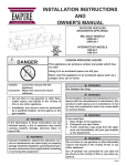
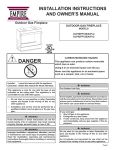
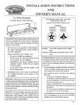
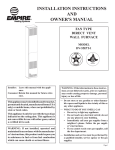
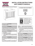
EMPIRE
Comfort Systems
Installation Instructions
And
Owner's Manual
OUTDOOR VENTLESS
DECORATIVE APPLIANCE
GAS-FIRED
! DANGER
INTERMITTENT IGNITION MODELS
OLI-24-1
OLI-30-1
CARBON MONOXIDE HAZARD
This appliance can produce carbon monoxide which has no
odor.
Using it in an enclosed space can kill you.
Never use this appliance in an enclosed space such as a camper, tent, car or home.
WARNING
For Outdoor Use Only.
Installer:Leave this manual with the appliance.
Consumer:Retain this manual for future reference.
— Do not store or use gasoline or other flammable vapors and liquids in the vicinity of this or any other appliance.
— Installation and service must be performed by a qualified installer, service agency or the gas supplier.
WARNING
If not installed, operated and maintained in accordance with the manufacturer's instructions, this
product could expose you to substances in fuel
or from fuel combustion which can cause death
or serious illness.
WARNING
WARNING
If the information in these instructions are
not followed exactly, a fire or explosion may
result causing property damage, personal
injury or loss of life.
If you smell gas:
1. Shut off gas to the appliance.
2. Extinguish any open flame.
3. If odor continues, keep away from the appliance and immediately call your gas supplier
or fire department.
WARNING
Improper installation, adjustment, alteration,
service or maintenance can cause injury
or property damage. Read the installation,
operating and maintenance instructions
thoroughly before installing or servicing this
equipment.
WARNING
Do not store or use gasoline or other flammable
vapors and liquids in the vicinity of this or any
other appliance.
An LP-cylinder not connected for use shall not
be stored in the vicinity of this or any other appliance.
Page 1
Table of Contents
Section Page
Important Safety Information........................................................................................................... 3
Safety Information for Users of LP-Gas.......................................................................................... 4
Introduction...................................................................................................................................5-7
General Information......................................................................................................................... 7
Clearances...................................................................................................................................... 8
Specifications.................................................................................................................................. 8
Before Fully Installing the Appliance............................................................................................... 8
Gas Supply...................................................................................................................................... 9
Operation Instructions/Flame Appearance.................................................................................... 10
OLI-(24,30) Lighting Instructions................................................................................................... 11
Main Burner Flame Characteristics............................................................................................... 12
Cleaning and Servicing................................................................................................................. 12
Wiring............................................................................................................................................ 12
Remote Control Installation and Operation................................................................................... 13
Parts View..................................................................................................................................... 14
Parts List....................................................................................................................................... 14
Master Parts Distributor List.......................................................................................................... 15
How To Order Repair Parts........................................................................................................... 15
Warranty Terms............................................................................................................................. 16
Page 2
28095-6-0115
IMPORTANT SAFETY INFORMATION
Installer: Please leave these instructions with the owner for future
reference.
This unit complies with ANSI Z21.97/CSA 2.41 Decorative Gas
Appliances For Installation In Solid Fuel Burning Fireplaces. Do not
burn wood or solid fuels in a fireplace where a decorative gas log
set is installed. This appliance is for installation only in a solid fuel
burning fireplace, masonry fireplace or manufactured fireplace.
Warning: Any modification to this appliance or to controls
can be dangerous. Improper installation or use of the gas log set
can cause serious injury or death from fire, burns, explosion or
carbon monoxide poisoning.
2.
Proper installation, burner pan location is important to achieve
optimum look and performance of your appliance.
3. Do not operate this appliance with glass doors in the closed
position. A fireplace screen must be in place when the appliance is burning.
4. Young children must be carefully supervised when they are
in the same room as the gas log while in operation. Do not
place stockings, clothing or any flammable material above or
near the fireplace.
5. Do not substitute or use materials other than those supplied
for use with the log set.
CAUTION:Sharp edges, wear protective gloves when installing appliance.
1. Please follow all local codes regarding installation, combustion and ventilation air or in the absence of local codes follow
the National Fuel Gas Code ANSI Z223.1(U.S. installation),
or CAN/CGA-B149, Installation Code (Canada installation).
Do Not Operate THIS GAS APPLIANCE With Glass Doors Closed.
DANGER: Indicates a hazardous situation which, if not
avoided, will result in death or serious injury.
WARNING: Indicates a hazardous situation which, if
not avoided, could result in death or serious injury.
CAUTION: Indicates a hazardous situation which, if not
avoided, could result in minor or moderate injury.
NOTICE: Addresses practices not related to personal injury.
•
•
•
•
•
•
Children and adults should be alerted to the hazards of
high surface temperatures and should stay away to avoid
burns or clothing ignition.
Young children should be carefully supervised when they
are in the same room as the appliance.
Clothing or other flammable material should not be placed
on or near the appliance.
Do not place trash or other articles on the log set during
operation.
During manufacturing, fabricating and shipping, various
components of this appliance are treated with certain oils,
films or bonding agents. These bonding agents are not
harmful but may produce annoying smoke and smells as
they are burned off during initial operation of the appliance.
This is a normal temporary occurrence.
Keep burner and control compartment clean.
28095-6-0115
•
•
•
•
•
Installation and repair should be done by a qualified
service person. The appliance should be inspected
before use and at least annually by a qualified service
person. More frequent cleaning may be required due to
excessive lint from carpeting, bedding materials, etc. It
is imperative that control compartments, burners and
circulating air passageways of the appliance be kept
clean.
Do keep the appliance area clear and free from combustible
material, gasoline and other flammable vapors and
liquids.
A yearly examination and cleaning of the venting system
of the solid-fuel burning fireplace must be performed by
a qualified agency.
Do make a periodic visual check of pilot and burners.
Clean and replace damaged parts.
Do not use this appliance if any part has been under
water. Immediately call a qualified service technician
to inspect the appliance and to replace any part of the
control system and any gas control which has been under
water.
Page 3
SAFETY INFORMATION FOR USERS OF LP-GAS
Propane (LP-Gas) is a flammable gas which can cause fires
and explosions. In its natural state, propane is odorless and
colorless. You may not know all the following safety precautions
which can protect both you and your family from an accident.
Read them carefully now, then review them point by point
with the members of your household. Someday when there
may not be a minute to lose, everyone's safety will depend
on knowing exactly what to do. If, after reading the following
information, you feel you still need more information, please
contact your gas supplier.
LP-GAS WARNING ODOR
•
•
•
•
If a gas leak happens, you should be able to smell the gas because of the odorant put in the LP-Gas.
That's your signal to go into immediate action!
Do not operate electric switches, light matches, use your
phone. Do not do anything that could ignite the gas.
Get everyone out of the building, vehicle, trailer, or area. Do
that IMMEDIATELY.
Close all gas tank or cylinder supply valves.
LP-Gas is heavier than air and may settle in low areas such
as basements. When you have reason to suspect a gas leak,
keep out of basements and other low areas. Stay out until
firefighters declare them to be safe.
•
Use your neighbor's phone and call a trained LP-Gas service
person and the fire department. Even though you may not
continue to smell gas, do not turn on the gas again. Do not
re-enter the building, vehicle, trailer, or area.
•Finally, let the service man and firefighters check for escaped
gas. Have them air out the area before you return. Properly
trained LP-Gas service people should repair the leak, then
check and relight the gas appliance for you.
no odor detected - odor fade
Some people cannot smell well. Some people cannot smell the
odor of the chemical put into the gas. You must find out if you
can smell the odorant in propane. Smoking can decrease your
ability to smell. Being around an odor for a time can affect your
sensitivity or ability to detect that odor. Sometimes other odors in
the area mask the gas odor. People may not smell the gas odor
or their minds are on something else. Thinking about smelling a
gas odor can make it easier to smell.
The odorant in LP-gas is colorless, and it can fade under some
circumstances. For example, if there is an underground leak, the
movement of the gas through soil can filter the odorant. Odorants
in LP-Gas also are subject to oxidation. This fading can occur if
there is rust inside the storage tank or in iron gas pipes.
The odorant in escaped gas can adsorb or absorb onto or into walls,
masonry and other materials and fabrics in a room. That will take
some of the odorant out of the gas, reducing its odor intensity.
LP-Gas may stratify in a closed area, and the odor intensity could
vary at different levels. Since it is heavier than air, there may be
more odor at lower levels. Always be sensitive to the slightest gas
odor. If you detect any odor, treat it as a serious leak. Immediately
go into action as instructed earlier.
some points to remember
•
Learn to recognize the odor of LP-gas. Your local LP-Gas
Dealer can give you a "Scratch and Sniff" pamphlet. Use it to
find out what the propane odor smells like. If you suspect that
your LP-Gas has a weak or abnormal odor, call your LP-Gas
Dealer.
•
If you are not qualified, do not light pilot lights, perform service,
or make adjustments to appliances on the LP-Gas system. If
you are qualified, consciously think about the odor of LP-Gas
prior to and while lighting pilot lights or performing service or
making adjustments.
•
Sometimes a basement or a closed-up house has a musty
smell that can cover up the LP-Gas odor. Do not try to light
pilot lights, perform service, or make adjustments in an area
where the conditions are such that you may not detect the
odor if there has been a leak of LP-Gas.
•
Odor fade, due to oxidation by rust or adsorption on walls of
new cylinders and tanks, is possible. Therefore, people should
be particularly alert and careful when new tanks or cylinders
are placed in service. Odor fade can occur in new tanks, or
reinstalled old tanks, if they are filled and allowed to set too
long before refilling. Cylinders and tanks which have been
out of service for a time may develop internal rust which will
Page 4
cause odor fade. If such conditions are suspected to exist,
a periodic sniff test of the gas is advisable. If you have any
question about the gas odor, call your lp-gas dealer. A
periodic sniff test of the lp-gas is a good safety measure
under any condition.
•
If, at any time, you do not smell the LP-Gas odorant and you
think you should, assume you have a leak. Then take the same
immediate action recommended above for the occasion when
you do detect the odorized LP-Gas.
•
If you experience a complete "gas out," (the container is under no vapor pressure), turn the tank valve off immediately.
If the container valve is left on, the container may draw in
some air through openings such as pilot light orifices. If this
occurs, some new internal rusting could occur. If the valve is
left open, then treat the container as a new tank. Always be
sure your container is under vapor pressure by turning it off
at the container before it goes completely empty or having it
refilled before it is completely empty.
28095-6-0115
Introduction
Product Components
Always consult your local Building Department regarding regulations, codes or ordinances which apply to the installation of a vented
decorative gas log set in a solid-fuel burning fireplace.
This appliance is only for use with the type of gas indicated on the
rating plate.
Instructions to Installer
1. Installer must leave instruction manual with owner after
installation.
2. Installer must have owner fill out and mail warranty card supplied
with the fireplace.
3. Installer should show owner how to start and operate the
fireplace.
WARNING
Any change to this appliance or its controls can
be dangerous.
Improper installation or use of the appliance can cause serious injury or death from fire, burns, explosion or carbon
monoxide poisoning.
Instructions to Installer
1. Installer must leave instruction manual with owner after
installation.
2. Installer must have owner fill out and mail warranty card supplied
with this fireplace.
3. Installer should show owner how to start and operate unvented
room heater.
Always consult your local Building Department regarding regulations,
codes or ordinances which apply to the installation of an unvented
room heater.
Important
All correspondence should refer to complete Model Number, Serial
Number and type of gas.
Moisture Resistance
This outdoor fireplace will shed moderate amounts of water, but is
not waterproof. Water and condensing water vapor may enter the
chase under certain conditions.
The fireplace will not perform as an exterior wall. Moisture penetration
must be considered for construction that places the fireplace in
structure walls or on moisture sensitive surfaces.
When installed on exterior walls: Empire Comfort Systems
recommends the fireplace chase be constructed outside the
structure's weather envelope. Where the platform meets the wall, use
a flashing detail similar to that required for attached decks. Chase
platforms, including hearths should slope away from the structure
at 1/4 in per foot. The fireplace can be shimmed level.
When installed on surfaces where water may collect or cause
damage: Empire Comfort Systems recommends a slope of 1/8 in
to 1/4 in per foot towards the drain port suggested. The fireplace
can be shimmed level.
Hearths should slope away from the front of the fireplace and chase
at 1/8 in to 1/4 in per foot. Metal safety strips must be on top of any
combustible hearth materials used for moisture management.
Screened Porch Installation
The fireplace may be installed safely and is design certified by CSA
to be installed in a screen porch with the following guidelines.
Minimum Porch Area
96 sq. feet (9 sq m)
Minimum Ceiling Height
92" (234 cm)
Minimum of two (2) walls must be screened
Minimum top of screen height, side walls
6'6" (198 cm)
Minimum screen area
64 sq. feet (6 sq m)
*Aftermarket: Completion of sale, not for purpose of resale, from
the manufacturer.
This appliance is only for use with the type of gas indicated on the
rating plate. This appliance is not convertible for use with other
gases.
Warning: Any change to this HEATER or its
controls can be dangerous.
Improper installation or use of the heater can cause serious
injury or death from fire, burns, explosion or carbon
monoxide poisoning.
This series is design certified in accordance with American National
Standard Z21.97.1/CSA 2.41 by the Canadian Standards Association
Laboratories as an Outdoor Gas Fireplace and should be installed
according to these instructions.
Any alteration of the original design, installed other than as
shown in these instructions or use with a type of gas not
shown on the rating plate is the responsibility of the person
and company making the change.
28095-6-0115
Page 5
Introduction
Qualified Installing Agency
Installation and replacement of gas piping, gas utilization equipment
or accessories and repair and servicing of equipment shall be
performed only by a qualified agency. The term "qualified agency"
means any individual, firm, corporation or company which either in
person or through a representative is engaged in and is responsible for
(a) the installation or replacement of gas piping or (b) the connection,
installation, repair or servicing of equipment, who is experienced in
such work, familiar with all precautions required and has complied
with all the requirements of the authority having jurisdiction.
State of Massachusetts: The installation must be made by
a licensed plumber or gas fitter in the Commonwealth of
Massachusetts.
Sellers of unvented propane or natural gas-fired supplemental
room heaters shall provide to each purchaser a copy of 527
CMR 30 upon sale of the unit.
In the Sate of Massachusetts, unvented propane and natural
gas-fired space heaters shall be prohibited in bedrooms and
bathrooms.
The installation must conform with local codes or, in the absence of
local codes, with the National Fuel Gas Code, ANSI Z223.1.*
*Available from the American National Standards Institute, Inc. 1430
Broadway, New York, N.Y. 10018.
High Altitudes
For altitudes/elevations above 2,000 feet (610m), ratings should be
reduced at the rate of 4 percent for each 1,000 feet (305m) above
sea level. Contact the manufacturer or your gas company before
changing spud/orifice size.
Well Head Gas Installations
Some natural gas utilities use "well head" gas. This may affect the
Btu output of the unit. Contact the gas company for the heating value.
Contact the manufacturer or your gas company before changing
spud/orifice size.
WARNING: This appliance is equipped for (natural gas or propane)
gas. Field conversion is not permitted.
•
When the appliance is connected to a fixed piping system,
the installation must conform with ocal codes, or in the absence of local codes with the National Fuel Gas Code, ANSI
Z223.1/NFPA 54, or International Fuel Gas Code.
•
When installed, the appliance must be electrically grounded
in accordance with local codes, or in the absence of local
codes with the National Electrical Code, ANSI/NFPA 70, if
applicable.
•
Solid fuels shall not be burned in this appliance.
•
The maximum gas inlet supply pressure is 13" for LP and
10.5" for NAT.
•
For appliances for fixed fuel piping system and equipped
with an appliance gas pressure regulator, the required manifold pressure in inches water column: 10" for LP and 3.5"
NAT.
Page 6
•
For appliances for fixed fuel piping system and equipped
with an appliance gas pressure regulator, the appliance and
its individual shutoff valve must be disconnected from the
gas supply piping system during any pressure testing of that
system at test pressures in excess of 1/2 psi (3.5 kPa).
The appliance must be isolated from the gas supply piping
system by closing its individual manual shutoff valve during
any pressure testing of the gas supply piping system at test
pressures equal to or less than 1/2 psi (3.5 kPa).
For an appliance designed for use with a non-disposable selfcontained LP-gas supply system:
•
Propane cylinders may be acceptable for use with the appliance provided they are are compatible with the appliance
retention means.
•
LP-gas supply cylinder must be constructed and marked
in accordance with the U.S. Department of Transportation
(D.O.T.) Specifications for LP-Gas Cylinders, or the Standard for Cylinders, Spheres and Tubes for Transportation
of Dangerous Goods and Commission, CAN/CSA-B339 as
applicable.
•
LP-gas supply cylinder must have an overfill prevention
device.
•
LP-gas supply cylinder must have a connection device compatible with the connection of the appliance.
•
If the appliance is equipped with a CGA No. 600 Cylinder
Connection Device, the cylinder must be disconnected when
the appliance is not in use.
•
If appliance is to be permanently connected to a gas piping
system from a remote supply tank, installation must be in accordance with local codes or, in the absence of local codes,
with the National Fuel Gas Codes ANSI Z223.1/NFPA 54.
Enclosures for LP-gas supply cylinders shall be ventilated by
openings at the level of the cylinder valve and at floor level. The
effectiveness of the opening(s) for purposes of ventilation shall
be determined with the LP-gas supply cylinder(s) in place. This
shall be accomplished by one of the following.
a. One side of the enclosure shall be completely open; or
b. For an enclosure having four sides, a top and a bottom:
1. At least two ventilation openings at cylinder valve
level shall be provided in the side wall, equally
sized, spaced at 180 degrees (3.14rad), and unobstructed. Each opening shall have a total free area
of not less than 1/2 square inch per pound (2.3 sq.
cm/kg) of stored fuel capacity and not less than a
total free area of 10 square inches (64.5 sq. cm).
28095-6-0115
Introduction
2. Ventilation opening(s) shall be provided at floor
level and shall have a total free area of not less
than 1/2 square inch per pound (3.2 sq. cm/kg) of
stored fuel capacity and not less than a total free
area of 10 square inches (64.5 sq. cm). If ventilation openings at floor level are in a side alll, there
shall be at least two openings. The bottom of the
openings shall be at floor level and the upper edge
no more than 5 inches (127 mm) above the floor.
The openings shall be equally sized, spaced at 180
degrees (3.14 rad) and unobstructed.
3. Every opening shall have minimum dimensions so
as to permit the entrance of a 1/8 inch (3.2 mm)
diameter rod.
•
Cylinder valves shall be readily accessible for hand operation. A door on the enclosure to gain access to the cylinder
valves is acceptable, provided it is non-locking and can be
opened without the use of tools.
•
There shall be aminimum clearance of 2 inches (51 mm)
between the lower surface of the floor of the LP-gas supply
cylinder enclosure and the ground.
•
The design of the appliance shall be such that (1) the LP-gas
supply cylinder(s) can be connected, disconnected and the
connections inspected and tested outside the cylinder enclosure; and (2) those connections which could be disturbed
when installing the cylinder(s) in the enclosure can be leak
tested inside the enclosure;
General Information
This series is design certified in accordance with American National
Standard/CSA Standard Z21.97 Outdoor Fireplace, respectively, by
the Canadian Standards Association as a Outdoor Decorative Appliance and should be installed according to these instructions.
Any alteration of the original design, installed other than as
shown in these instructions or use with a type of gas not
shown on the rating plate is the responsibility of the person
and company making the change.
Important
All correspondence should refer to complete Model Number, Serial
Number and type of gas.
Gas Inlet
3/8" (9.5mm)
Qualified Installing Agency
Installation and replacement of gas piping, gas utilization equipment
or accessories and repair and servicing of equipment shall be performed only by a qualified agency. The term "qualified agency" means
any individual, firm, corporation or company which either in person
or through a representative is engaged in and is responsible for (a)
the installation or replacement of gas piping or (b) the connection,
installation, repair or servicing of equipment, who is experienced in
such work, familiar with all precautions required and has complied
with all the requirements of the authority having jurisdiction.
High Altitude Installation
When installing this unit at an elevation above 2000 feet (in the
United States) it may be necessary to decrease the input rating by
changing the existing burner orifice to a smaller size. Generally,
input should be reduced 4 percent for each 1000 feet above sea
level. However, if the heating value of the gas has been reduced,
this general rule may not apply. Check with local gas utility for proper
orifice size identification.
For Canadian high altitude applications, this appliance is suitable for
installation at elevations between 0 feet (0m) and 4,500 (1,370m)
without change.
When installing this unit at an elevation above 4500 feet (1,370m)
(in Canada), check with local authorities.
Consult your local gas utility for assistance in determining the proper
orifice for location.
State of Massachusetts: The installation must be made
by a licensed plumber or gas fitter in the Commonwealth of
Massachusetts.
The installation and the provisions for combustion and ventilation
air must conform with the National Fuel Gas Code, ANSI Z223.1/
NFPA54* Canadian Installation Code CAN/CGA B149.
*Available from the American National Standards Institute, Inc. 11
West 42nd St., New York, N.Y. 10018.
28095-6-0115
Page 7
CLEARANCES
Minimum Dimensions For Solid Fuel Burning Fireplaces
Model
A
B
C
D
OLI-24
27"
18"
34"
18"
OLI-30
30"
18"
36"
18"
Glass Doors
Make sure that glass doors are open during all operations of the
appliance. The opening of the glass door frame should be the
dimension used for the minimum front opening of the firebox.
The dimensions shown and defined in the fireplace instructions
are minimum clearances to maintain in installing this heater. Left
and right clearances are determined when facing the front of the
heater.
Follow these instructions to ensure safe installation.
Failure to follow instructions exactly can create a fire hazard.
SPECIFICATIONS
MODEL
OLI24P
OLI24N
OLI30P
OLI30N
Input BTU/Hr Maximum
36,000
36,000
40,000
40,000
Input BTU/Hr Minimum
28,000
27,000
28,000
28,000
#50
#31
#49
#31
FULL OPEN
1/8" OPEN
FULL OPEN
1/8" OPEN
Orifice
Air Shutter Opening
Before Fully installing the appliance
You must secure the gas burner to the firebox floor. If not, the
entire unit may move when you adjust the controls.
ANCHOR SCREWS
1. Center the gas burner in the fireplace or firebox. The burner
must clear the firebox screen.
2. An anchor hole is provided in the two bottom side burner. After
centering the burner correctly, mark the hole positions on the
firebox floor. Drill two (2) 5/32" diameter holes approximately
1-1/2" deep for masonry screws or 1/8" hole for sheet metal
screws.
3. Anchor the burner to the firebox floor using the screws provided.
Figure 1
Page 8
28095-6-0115
gas supply
Check all local codes for requirements, especially for the size and
type of gas supply line required.
Recommended Gas Pipe Diameter
Pipe Length
Schedule 40 Pipe
Inside Diameter
Tubing, Type L
Outside Diameter
Nat.
L.P.
Nat.
L.P.
0-10 feet
0-3 meters
1/2”
12.7mm
3/8”
9.5mm
1/2”
12.7mm
3/8”
9.5mm
10-40 feet
4-12 meters
1/2”
12.7mm
1/2”
12.7mm
5/8”
15.9mm
1/2”
12.7mm
40-100 feet
13-30 meters
1/2”
12.7mm
1/2”
12.7mm
3/4”
19mm
1/2”
12.7mm
100-150 feet
31-46 meters
3/4”
19mm
1/2”
12.7mm
7/8”
22.2mm
3/4”
19mm
NOTICE: Never use plastic pipe. Check to confirm whether your
local codes allow copper tubing or galvanized.
NOTICE: Since some municipalities have additional local codes, it is
always best to consult your local authority and installation code.
Installing a New Main Gas Cock
Each appliance should have its own manual gas cock.
In the state of Massachusetts the gas cock must be a T handle
type.
A manual main gas cock should be located in the vicinity of the unit.
Where none exists, or where its size or location is not adequate,
contact your local authorized installer for installation or relocation.
Compounds used on threaded joints of gas piping shall be resistant
to the action of liquefied petroleum gases. The gas lines must be
checked for leaks by the installer. This should be done with a soap
solution watching for bubbles on all exposed connections, and if
unexposed, a pressure test should be made.
Never use an exposed flame to check for leaks. Appliance must
be disconnected from piping at inlet of control valve and pipe
capped or plugged for pressure test. Never pressure test with
appliance connected; control valve will sustain damage!
A gas valve and ground joint union should be installed in the gas
line upstream of the gas control to aid in servicing. It is required by
the National Fuel Gas Code that a drip line be installed near the gas
inlet. This should consist of a vertical length of pipe tee connected
into the gas line that is capped on the bottom in which condensation
and foreign particles may collect.
The use of the following gas connectors is recommended:
— ANS Z21.24 Appliance Connectors of Corrugated Metal Tubing
and Fittings
— ANS Z21.45 Assembled Flexible Appliance Connectors of Other
Than All-Metal Construction
Figure 2
Pressure Testing of the Gas Supply System
1. To check the inlet pressure to the gas valve, a 1/8" (3.175mm)
N.P.T. plugged tapping, accessible for test gauge connection, must
be placed immediately upstream of the gas supply connection
to the appliance.
2. The appliance and its individual shutoff valve must be disconnected
from the gas supply piping system during any pressure testing of
that system at test pressures in excess of 1/2 psig (3.5 kPa).
3. The appliance must be isolated from the gas supply piping system
by closing its individual manual shutoff valve during any pressure
testing of the gas supply piping system at test pressures equal
to or less than 1/2 psig (3.5 kPa).
Attention! If one of the procedures results in pressures in excess
of 1/2 psig (14" w.c.) (3.5 kPa) on the appliance gas valve, it will
result in a hazardous condition.
Checking Manifold Pressure
Natural gas models will have a manifold pressure of approximately
3.5" w.c. (.871kPa) at the pressure regulator outlet with the inlet
pressure to the pressure regulator from a minimum of 5.0" w.c.
(1.120kPa) for the purpose of input adjustment to a maximum of
10.5" w.c. (2.615kPa).
Propane gas models will have a manifold pressure approximately
10.0" w.c. (2.49kPa) at the pressure regulator outlet with the inlet
pressure to the pressure regulator from a minimum of 11.0" w.c.
(2.739kPa) for the purpose of input adjustment to a maximum of
13.0" w.c. (3.237kPa).
OLI
NOTICE: The gas control is equipped with a captured screw type
pressure test point, therefore it is not necessary to provide a 1/8"
test point up stream of the control.
The above connectors may be used if acceptable by the authority
having jurisdiction. The state of Massachusetts requires that a flexible
appliance connector cannot exceed three feet in length.
28095-6-0115
Page 9
operation instructionS/flame appearance
NOTICE: all flames will be random by design, flame height will go
up and down.
During manufacturing, fabricating and shipping, various components
of this appliance are treated with certain oils, films or bonding agents.
These chemicals are not harmful, but may produce annoying smoke
and smells as they are burned off during the initial operation of the
appliance, possibly causing headaches or eye or lung irritation. This
is a normal and temporary occurrence.
The initial break-in operation should last 2-3 hours with the burner
at the highest setting. Any odors remaining after this initial break-in
will be slight and will disappear with continued use.
PERIODIC CLEANING – Refer to parts diagram for location of
items discussed below.
• Do not use cleaning fluid to clean any part of heater.
• Remove loose particles and dust from the burner areas,
controls, covers and grate.
• Inspect and clean burner air intake hole. Remove lint or particles
with brush. Failure to keep air intake hole clean will result in
sooting and poor combustion.
Millivolt - Figure 3
ANNUAL CLEANING/INSPECTION – Refer to parts diagram for
location of items discussed below.
• Inspect and clean burner air intake hole. Remove lint or particles
with vacuum or brush. Failure to keep air intake hole clean will
result in sooting and poor combustion.
• Inspect and clean all burner ports.
• Inspect pilot for operation and accumulation of lint at air intake
holes.
• Verify flame pattern and log placement for proper operation.
• Verify smooth and responsive ignition of main burner.
REMOVING THE BURNER TOP
• Grasp front left and right corners of the burner.
• Lift upward to release the corners from the bottom.
• Slide the top to the right and lift up the rear burner top.
BATTERY INSTALLATION
• Install the provided batteries into the hand held transmitter and
receiver.
RECEIVER INSTALLATION
• Install the receiver to the right of the large opening in burner
bottom.
Page 10
28095-6-0115
OLI-(24,30) Lighting Instructions
FOR YOUR SAFETY READ BEFORE LIGHTING
WARNING: IF YOU DO NOT FOLLOW THESE INSTRUCTIONS EXACTLY, A FIRE OR
EXPLOSION MAY RESULT CAUSING PROPERTY DAMAGE, PERSONAL INJURY, OR
LOSS OF LIFE.
A. BEFORE LIGHTING, smell around the appliance area for
gas. Be sure to smell next to the floor because some gas
in heavier than air and will settle on the floor.
WHAT TO DO IF YOU SMELL GAS
• Do not try to light any appliance.
• Do not touch any electrical switch.
• Do not use any phone in your building.
• Immediately call your gas supplier from a
neighbor's phone. Follow the gas supplier's
instructions. If you can not reach your gas
supplier, call the fire department.
B.Use only your hand to push in or turn the gas control
knob. Never use tools. If the knob will not push in or
turn by hand, don't try to repair it, call a qualified service
technician. Force or attempted repair may result in a fire
or explosion.
C.Do not use this appliance if any part has been under water.
Immediately call a qualified service technician to inspect
the appliance and to replace any part of the control system
and any gas control which has been under water.
LIGHTING INSTRUCTIONS
1.STOP! Read the safety information above.
to "ON"
2.Turn gas cock counterclockwise
position.
3.Wait ten (10) minutes to clear out any gas. Then smell
for gas, including near the floor. If you smell gas, STOP!
Follow "B" in the safety information above on this label.
If you do not smell gas, go to the next step.
4.Turn ON electric power to the appliance.
5. Find spark and sensor probes.
6. Using the remote control, turn main flame to "ON." If the
burner does not light within 60 seconds, stop and go to
Step 5.
SENSING
PROBE
SPARKING PROBE
7. If the burner does not stay lit, stop and immediately call
a qualified service technician or gas supplier.
8. If the burner does not operate properly after several tries,
turn the gas control knob clockwise
to "OFF"
and call your service technician or gas supplier.
9.Operation of the gas valve must be controlled by using
the hand held remote control. Refer to remote instructions
for detailed operation information.
OFFProvided by installer.ON
TO TURN OFF GAS TO APPLIANCE
1.Locate On/Off gas cock and turn clockwise to
"OFF." Do not force.
28095-6-0115
Page 11
main burner flame characteristics
Main Burner Flame Pattern
The main burner flame will be completely yellow.
Main Burner Flame Ignition and Extinction
When the main burner is ignited it will take a few seconds for the
full flame pattern to develop.
When the main burner is extinguished it will take a few seconds for
the flames to disappear.
Cleaning and servicing
Keep the control compartment and burner area surrounding the
burner clean.
Always keep the appliance area clear and free from combustible
materials, gasoline, and other flammable vapors and liquids.
Never obstruct the flow of combustion and ventilation air. Keep the
front of the appliance clear of all obstacles and materials.
Cleaning Instructions
This appliance is built using mostly high-grade stainless steel to
resist rust-through. In outdoor applications, all stainless steel will
develop a dull patina and, depending on the local environment
and on the materials used in the installation, may develop some
surface oxidation (rust). This does not affect the performance of
the fireplace, and does not require any action to correct. If you
prefer keeping your fireplace front looking factory-fresh, clean it as
required with stainless steel cleaner.
When installation application includes highly acidic applications
such as mortar or stone etching, do not remove the protective PVC
film from the stainless steel until after this application is complete.
Once the film has been removed we recommend that the appliance be cleaned with a stainless steel cleaner immediately.
Please note that areas where the film has been formed (corners,
hems, etc.) may require extra cleaning due to the properties of
the film. Ensure that all protective film has been removed from the
fireplace prior to burning the appliance.
Wiring
CUSTOMER PROVIDED
WALL SWITCH
N/A
BROWN
(GND)
Learn MOTOR COMM.
MAIN
IPI
PILOT
Continuous
Pilot
Off/On
Remote/Off
BLACK
HI/LO
Solenoid
GREEN
POWER
WHITE
ORANGE
GAS CONTROL
VALVE
ADJ.
S
PILOT
I
BLACK
(SENSOR)
ELECTRONIC
CONTROL MODULE
ORANGE
(IGNITOR)
AF-4000 B/P
RED
Page 12
BLACK
ORANGE
RED
BROWN
BLACK
Note: The fireplace may be operated without the remote by
connecting the brown control module wires to a wall switch. The
remote/off switch on the control module must be in the "OFF"
position.
28095-6-0115
REMOTE CONTROL INSTALLATION & OPERATION
TWO-FUNCTION WIRELESS REMOTE CONTROL SYSTEM
FOR ON/OFF-HI/LO OPERATION OF THE AF-4000 GAS CONTROL VALVE
IF YOU CANNOT READ OR UNDERSTAND THESE INSTALLATION INSTRUCTIONS DO NOT
ATTEMPT TO OPERATE
INTRODUCTION
This remote control system was developed to provide a safe, reliable, and user-friendly remote control system for use with the AF-4000
gas control valve used with some gas heating appliances. The system operates on radio frequencies (RF) within a 20’ range using nondirectional signals. The system operates on one of 255 security codes that are programmed into the transmitter at the factory; the remote
receiver must learn the transmitter code prior to initial use.
TRANSMITTER
This remote control TRANSMITTER offers the user a battery-operated hand held control to
operate the AF-4000 control module functions that are used with some decorative gas fireplaces and other gas heating appliances.
The transmitter operates with a 12V battery (Included) made specifically for remote controls
and electronic lighters. Before using the transmitter, install the 12-volt (A-23) battery in the
battery compartment.
It is recommended that ALKALINE batteries always be used for longer battery life and maximum operational performance.
The transmitter has ON/OFF and HI/LO functions that are activated by pressing the button
on the face of the transmitter. When a button on the transmitter is pressed, a signal light on
the transmitter illuminates to verify that a signal is being sent. Upon initial use, there may be
a delay of three seconds before the remote receiver will respond to the transmitter. This is
part of the system’s design. If the signal light does not illuminate, check the position of the
transmitter’s battery.
MATCHING SECURITY CODES
Each transmitter can use one of 255 unique security codes. It may be necessary to program (LEARN FUNCTION) the module to accept
the transmitter security code upon initial use, if batteries are replaced, or if a replacement transmitter is purchased from your dealer or the
factory. In order for the module to accept the transmitter security code, be sure the slide button on the module is in the REMOTE position;
the module will NOT “LEARN” if the slide switch is in the OFF position. Press and release the LEARN button on the module to accept the
transmitter security code and then pressing any button on the transmitter. A change in the beeping pattern, at the module, indicates the
transmitter’s code has been accepted into the module. When an existing module has accepted the new transmitter code, the new security
code will replace the old one.
The microprocessor that controls the security code matching procedure is controlled by a timing function. If you are unsuccessful in
matching the security code on the first attempt, wait 1 - 2 minutes before trying again - this delay allows the microprocessor to reset its
timer circuitry - and try up to two or three more times.
OPERATION
1. This remote control will operate the AF-4000 gas control valves ON/OFF and flame height HI/LO of the main burner.
2. When the ON button is depressed the transmitter sends a RF signal to the module. The module then sends 3 volts of power to the
internal solenoid. The internal solenoid then opens the gas flow to the main burner ON/OFF. The system uses a pulse or continuous
3 volts DC power to operate the flame HI/LO solenoid or flame HI/LOW DC motor drive.
BATTERY LIFE
Life expectancy of the alkaline batteries in the RCAF-3 TX can be up to 12 months depending on use of the solenoid function. Check and
replace all batteries annually. The transmitter should operate with as little as 9.0 volts battery power.
SPECIFICATIONS
BATTERIES:
Transmitter 12V - (A23)
Operating Frequency: 303.8 MHZ
FCC ID No.’s: transmitter K9l1001
Canadian ISC ID No.’s: transmitter - 2439 102 728
FCC REQUIREMENTS
NOTE: THE MANUFACTURER IS NOT RESPONSIBLE FOR ANY RADIO OR TV INTERFERENCE CAUSED BY UNAUTHORIZED
MODIFICATIONS TO THIS EQUIPMENT. SUCH MODIFICATIONS COULD VOID THE USER’S AUTHORITY TO OPERATE THE
EQUIPMENT.
28095-6-0115
Page 13
Parts view
Parts List
Index No.
Part No.
Description
OLI24
OLI30
1
28103
28105
Top Cover
2
27972
27972
Inlet Tubing
3
P212
P212
Orifice Holder
4
P245
P265
Orifice - LP
4
P301
P209
Orifice - NAT
5
R10808
R10808
6
28739
28740
Air Shutter
Burner with Bracket
7
R10814
R10814
Spark Probe
8
28089
28089
Valve Shield
9
R10810
R10810
Gas Valve - LP
9
R12005
R12005
Gas Valve - NAT
10
R10812
R10812
Harness Wire
11
28106
28109
Bottom
12
28111
28111
13
R10811
R10811
Module
Module Shield
14
R10815
R10815
Transmitter Remote Control
15
R10813
R10813
Battery Pack
N/S
27802
27802
Spark Probe Bracket
Use Only Manufacturer's Replacement Parts. Use of Any Other Parts Could Cause Injury Or Death.
Page 14
28095-6-0115
MASTER PARTS DISTRIBUTOR LIST
To Order Parts Under Warranty, please contact your local Empire dealer. See the dealer locator at www.empirecomfort.
com. To provide warranty service, your dealer will need your name and address, purchase date and serial number, and the
nature of the problem with the unit.
To Order Parts After the Warranty Period, please contact your dealer or one of the Master Parts Distributors listed below.
This list changes from time to time. For the current list, please click on the Master Parts button at www.empirecomfort.com.
Please note: Master Parts Distributors are independent businesses that stock the most commonly ordered Original
Equipment repair parts for Heaters, Grills, and Fireplaces manufactured by Empire Comfort Systems Inc.
Dey Distributing
1401 Willow Lake Boulevard
Vadnais Heights, MN 55101
Victor Division of F. W. Webb Company
200 Locust Street
Hartford, CT 06114
Phone: 651-490-9191
Toll Free: 800-397-1339
Website: www.deydistributing.com
Parts: Heater, Hearth and Grills
Phone: 860-722-2433
Toll Free: 800-243-9360
Fax: 860-293-0479
Toll Free Fax: 800-274-2004
Websites: www.fwwebb.com & www.victormfg.com
Parts: Heater, Hearth and Grills
East Coast Energy Products
10 East Route 36
West Long Branch, NJ 07764
Able Distributors
2501 North Central Avenue
Chicago, IL 60639
Phone: 732-870-8809
Toll Free: 800-755-8809
Fax: 732-870-8811
Website: www.eastcoastenergy.com
Parts: Heater, Hearth and Grills
Phone: 773-889-5555
Toll Free: 800-880-2253
Fax: 773-466-1118
Website: www. abledistributors.com
Parts: Heater
HOW TO ORDER REPAIR PARTS
Parts Not Under Warranty
Parts can be ordered through your Service Person, Dealer, or a Master Parts Distributor. See this page for the Master Parts Distributors list. For best results, the service person or dealer should order parts through the distributor. Parts can be shipped directly to the
service person/dealer.
Warranty Parts
Warranty parts will need a proof of purchase and can be ordered by your Service Person or Dealer. Proof of purchase is required for
warranty parts.
All parts listed in the Parts List have a Part Number. When ordering parts, first obtain the Model Number and Serial Number from the
name plate on your equipment. Then determine the Part Number (not the Index Number) and the Description of each part from the following illustration and part list. Be sure to give all this information . . .
Appliance Model Number
Appliance Serial Number
Part Description
Part Number
Type of Gas (Propane or Natural)
Do not order bolts, screws, washers or nuts. They are standard hardware items and can be purchased at any local hardware store.
Shipments contingent upon strikes, fires and all causes beyond our control.
28095-6-0115
Page 15
WARRANTY TERMS
Empire Comfort Systems Inc. warranties this hearth product to be free from defects at the time of purchase and for the periods specified below. Hearth products must be installed by a qualified technician and must be maintained and operated
safely, in accordance with the instructions in the owner’s manual. This warranty applies to the original purchaser only and
is not transferable. All warranty repairs must be accomplished by a qualified gas appliance technician.
Limited Five-Year Parts Warranty – All Components
(Except Remote Controls, Thermostats, Accessories and Replacement Parts)
Should any part fail because of defective workmanship or material within five years from the date of purchase,
Empire will repair or replace at Empire’s option.
Limited One-Year Parts Warranty – Remote Controls, Thermostats, Accessories, and Parts
Should any remote control, thermostat, accessory, or other part fail because of defective workmanship within one
year from the date of purchase, Empire will repair or replace at Empire’s option.
Duties of the Owner
The appliance must be installed by a qualified installer and operated in accordance with the instructions furnished
with the appliance.
A bill of sale, cancelled check, or payment record should be kept to verify purchase date and establish warranty
period.
Ready access to the appliance for service.
What Is Not Covered
Damages that might result from the use, misuse, or improper installation of this appliance.
Travel, diagnostic costs and freight charges on warranted parts to and from the factory.
Claims that do not involve defective workmanship or materials.
Unauthorized service or parts replacements.
Removal and reinstallation cost.
Inoperable due to improper or lack of maintenance.
How To Get Service
To make a claim under this warranty, please have your receipt available and contact your installing dealer. Provide the dealer with the model number, serial number, type of gas, and purchase verification. The installing dealer is responsible for providing service and will contact the factory to initiate any warranted parts replacements. Empire will make
replacement parts available at the factory. Shipping expenses are not covered.
If, after contacting your Empire dealer, service received has not been satisfactory, contact: Consumer Relations
Department, Empire Comfort Systems Inc., PO Box 529, Belleville, Illinois 62222, or send an e-mail to [email protected] with “Consumer Relations” in the subject line.
Your Rights Under State Law
This warranty gives you specific legal rights, and you may also have other rights, which vary from state to state.
EMPIRE
Comfort Systems
Empire Comfort Systems Inc.
918 Freeburg Ave. Belleville, IL 62220
If you have a general question about our products, please e-mail us at
[email protected].
If you have a service or repair question, please contact your dealer.
www.empirecomfort.com
Page 16
28095-6-0115