1
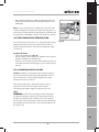
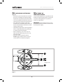
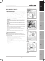
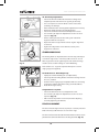
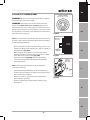
EN DE STEALTH 255 255 Original Instructions FR IT JP NL Written in UK English V1 Date Published: 07 / 05 / 2014 www.evolutionpowertools.com TABLE OF CONTENTS* English Page 02 Deutsch Seite 40 Français Page 82 Italiano Pagina 126 日本語 ページ 168 Nederlands Pagina 204 MACHINE SPECIFICATION 04 Introduction 06 Guarantee 06 Vibration 07 Intended use of this Power Tool 08 Prohibited use of this Power Tool 08 SAFETY PRECAUTIONS 08 Electrical Safety 08 General Power Tool Safety Instructions 08 Health Advice 10 Specific Safety Instructions 11 Personal Protective Equipment (PPE) 11 Safe Operation 12 Additional Safety Advice 12 GETTING STARTED 13 Unpacking 13 Additional Accessories 13 Machine Overview 14 Assembly and Preparation 15 Operating Instructions 21 Use of Additional Accessories 34 Final Safety Check List 36 MAINTENANCE 37 Care and Cleaning 37 Environmental Protection 37 EC Declaration of Conformities 38 *This manual is originally written in UK English. 2 www.evolutionpowertools.com EN DE FR IT JP NL 3 www.evolutionpowertools.com 210mm (8-1/4”) TCT MULTIPURPOSE SLIDING MITRE SAWS MACHINE SPECIFICATIONS METRIC IMPERIAL Motor UK (230V ~ 50/60 Hz) 1500W 7A Motor UK (110V ~ 50/60 Hz) 1500W 14A Motor USA (120V ~ 60 Hz) 1500W No Load Speed 3750min Weight 13A 3750rpm -1 N: 13kg / G: 14.6kg N: 29lb / G: 32lb 6mm 1/4” CUTTING CAPACITIES Mild Steel Plate (Max Thickness) 3mm 1/8” 0° Mitre / 0° Bevel Cut 220 x 60mm 8-3/4 x 2-3/8” 45° Mitre / 45° Bevel Cut 140 x 35mm 5-1/2 x 1-3/8” 45° Mitre / 0° Bevel Cut 140 x 60mm 5-1/2 x 2-3/8” 0° Mitre / 45° Bevel Cut 220 x 35mm 8-3/4 x 1-3/8” Diameter 210mm 8-1/4” Arbor Diameter 25.4mm 1” Max Speed 4000min 4000rpm Thickness 1.7mm Mild Steel Box Section (Max Wall Thickness) BLADE DIMENSIONS -1 2/8” LASER Class 2 Laser Class Laser Source Laser Diode Laser Power 1 Max mW Wave Length 650nm NOISE & VIBRATION DATA Sound Pressure Level 110V: 95.29 dB (A) 230V: 94.54 dB (A) K = 3 dB(A) Sound Power Level 110V: 108.29 dB (A) 230V: 107.54 dB (A)K = 3 dB(A) Vibration Level 110V: 2.339 m/s2 230V: 2.561 m/s2 K = 1.5m/s2 4 www.evolutionpowertools.com EN STEALTH 210mm (8-1/4”) TCT MULTIPURPOSE SLIDING MITRE SAW WITH 300mm SLIDE 255 255 255mm (10”) TCT MULTIPURPOSE SLIDING MITRE SAWS METRIC IMPERIAL METRIC IMPERIAL 1500W 7A 2000W (Soft Start) 9A (Soft Start) 1500W 14A 1600W (Soft Start) 15A (Soft Start) 1500W 13A 1800W (Soft Start) 15A (Soft Start) 3000min-1 3000rpm 2500min-1 2500rpm N: 13kg / G: 17kg N: 23lb / G:38 lb N: 19.6kg / G: 21kg N: 43lb / G: 46lb 6mm 1/4” 6mm 1/4” 3mm 1/8” 3mm 1/8” 300 x 60mm 11-3/4 x 2-3/8” 300 x 75mm 11-3/4 x 3” 210 x 35mm 8-1/4 x 1-3/8” 210 x 40mm 8-1/4 x 1-5/8” 210 x 60mm 8-1/4 x 2-3/8” 210 x 75mm 8-1/4 x 3” 300 x 35mm 11-3/4 x 1-3/8” 300 x 40mm 11-3/4 x 1-5/8” 210mm 8-1/4” 255mm 10” 25.4mm 1” 25.4mm 1” 4000min-1 4000rpm 2500min-1 2500rpm 1.7mm 2/8” 2mm 2/8” Class 2 Class 2 Laser Diode Laser Diode 1 Max mW 1 Max mW 650nm 635 - 670nm 95 dB (A) K = 3 dB(A) 90.37 dB (A) K = 3 dB (A) 108 dB (A)K = 3 dB(A) 103.37 dB (A) K = 3 dB (A) 3.236 m/s2 K = 1.5m/s2 2.944m/s2 K = 1.5m/s2 DE FR IT JP NL 5 www.evolutionpowertools.com (1.3) IMPORTANT Please read these operating and safety instructions carefully and completely. For your own safety, if you are uncertain about any aspect of using this equipment please access the relevant Technical Helpline, the number of which can be found on the Evolution Power Tools website. We operate several Helplines throughout our worldwide organization, but Technical help is also available from your supplier. WEB www.evolutionpowertools.com/register EMAIL [email protected] (1.4) Congratulations on your purchase of an Evolution Power Tools Machine. Please complete your product registration ‘online’ as explained in the A4 online guarantee registration leaflet included with this machine. You can also scan the QR code found on the A4 leaflet with a Smart Phone. This will enable you to validate your machine’s guarantee period via Evolutions website by entering your details and thus ensure prompt service if ever needed. We sincerely thank you for selecting a product from Evolution Power Tools. EVOLUTION LIMITED GUARANTEE Evolution Power Tools reserves the right to make improvements and modifications to the product design without prior notice. Please refer to the guarantee registration leaflet and/or the packaging for details of the terms and conditions of the guarantee. 6 (1.5) Evolution Power Tools will, within the guarantee period, and from the original date of purchase, repair or replace any goods found to be defective in materials or workmanship. This guarantee is void if the tool being returned has been used beyond the recommendations in the Instruction Manual or if the machine has been damaged by accident, neglect, or improper service. This guarantee does not apply to machines and / or components which have been altered, changed, or modified in any way, or subjected to use beyond recommended capacities and specifications. Electrical components are subject to respective manufacturers’ warranties. All goods returned defective shall be returned prepaid freight to Evolution Power Tools. Evolution Power Tools reserves the right to optionally repair or replace it with the same or equivalent item. There is no warranty – written or verbal – for consumable accessories such as (following list not exhaustive) blades, cutters, drills, chisels or paddles etc. In no event shall Evolution Power Tools be liable for loss or damage resulting directly or indirectly from the use of our merchandise or from any other cause. Evolution Power Tools is not liable for any costs incurred on such goods or consequential damages. No officer, employee or agent of Evolution Power Tools is authorized to make oral representations of fitness or to waive any of the foregoing terms of sale and none shall be binding on Evolution Power Tools. Questions relating to this limited guarantee should be directed to the company’s head office, or call the appropriate Helpline number. www.evolutionpowertools.com EN (1.7) VIBRATION WARNING: When using this machine the operator can be exposed to high levels of vibration transmitted to the hand and arm. It is possible that the operator could develop “Vibration white finger disease” (Raynaud syndrome). This condition can reduce the sensitivity of the hand to temperature as well as producing general numbness. Prolonged or regular users of mitre saws should monitor the condition of their hands and fingers closely. If any of the symptoms become evident, seek immediate medical advice. a. The actual vibration level during use will depend on the workpiece stability/ rigidity and the condition of the cutter being used. These factors may increase the vibration experienced by the operator. Each individual application of the tool should be assessed for the effect of these application variable factors, before exposure. WARNING: The vibration emission during actual use of the power tool can differ from the declared total value depending on the ways in which the tool is used. The need to identify safety measures and to protect the operator are based on an estimation of exposure in the actual conditions of use (taking account of all parts of the operating cycle, such as the times the tool is switched off, when it is running idle, in addition to trigger time). DE (1.8) SAFETY LABELS & SYMBOLS WARNING: Do not operate this machine if warning and/or instruction labels are missing or damaged. Contact Evolution Power Tools for replacement labels. Note: All or some of the following symbols may appear in the manual or on the product. Symbol b. The measurement and assessment of human exposure to hand-transmitted vibration in the workplace is given in: BS EN ISO 5349-1:2001 and BS EN ISO 5349-2:2002 c) The following factors can influence the level of vibration. Reducing these factors will help to reduce the effects of vibration: FR Description V Volts A Amperes Hz Hertz Min-1 (RPM) Speed ~ Alternating Current no No Load Speed IT Wear Safety Goggles Wear Ear Protection Handling: • Handle the machine with care, allowing the machine to do the work. • Avoid using excessive physical effort on any of the machines controls. • Consider your security and stability, and the orientation of the machine during use. Do Not Touch, Keep hands away Wear Dust Protection CE certification JP Waste electrical and electronic equipment Read Manual Workpiece: • Consider the work surface material; its condition, density, strength, rigidity and orientation. WARNING Laser Warning Double Insulation Protection CSA certification 7 NL www.evolutionpowertools.com INTENDED USE OF THIS POWER TOOL (1.14) WARNING: This product is a Multipurpose Sliding Mitre Saw and has been designed to be used with special Evolution Multipurpose blades. Only use blades designed for use in this machine and/or those recommended specifically by Evolution Power Tools Ltd. This machine is fitted with the correct moulded plug and mains lead for the designated market. If the supply cord is damaged, it must be replaced by a special cord or assembly available from the manufacturers or its service agent. WHEN FITTED WITH A CORRECT BLADE THIS MACHINE CAN BE USED TO CUT: (1.15) ELECTRICAL SAFETY OUTDOOR USE WARNING: For your protection if this tool is to be used outdoors it should not be exposed to rain, or used in damp locations. Do not place the tool on damp surfaces. Use a clean, dry workbench if available. For added protection use a residual current device (R.C.D.) that will interrupt the supply if the leakage current to earth exceeds 30mA for 30ms. Always check the operation of the residual current device (R.C.D.) before using the machine. If an extension cable is required it must be a suitable type for use outdoors and so labelled. The manufacturers instructions should be followed when using an extension cable. Wood Wood derived products (MDF, Chipboard, Plywood, Blockboard, Hardboard etc) Aluminium Mild Steel (6mm / 1/4” Thickness) Note: Wood containing non galvanised nails or screws can, with care, can be safely cut PROHIBITED USE OF THIS POWER TOOL WARNING: This product is a Multipurpose Sliding Mitre Saw and must only be used as such. It must not be modified in any way, or used to power any other equipment or drive any other accessories other than those mentioned in this Instruction Manual. (2.1) POWER TOOL GENERAL SAFETY INSTRUCTIONS (These General Power Tool Safety Instructions are as specified in BS EN 60745-1:2009 & EN 61029-1:2009) (1.13) WARNING: When using electric tools basic WARNING: This product is not intended safety precautions should always be followed to reduce the risk of fire, electric shock and personal injury including the following. for use by persons (including children) with reduced physical, sensory or mental capabilities, or lack of experience and knowledge, unless they have been given supervision or instruction concerning the safe use of the product by a person responsible for their safety and who is competent in its safe use. Read all these instructions before attempting to operate this product and save these instructions. WARNING: Read all safety warnings and instructions. Failure to follow the warnings and instructions may result in electric shock, fire and/ or serious injury. 8 www.evolutionpowertools.com EN SAVE ALL WARNINGS & INSTRUCTIONS FOR FUTURE REFERENCE The term “power tool” in the warnings refers to your mains-operated (corded) power tool or battery-operated (cordless) power tool. (2.2) 1. General Power Tool Safety Warnings [Work area safety] a. Keep work area clean and well lit. Cluttered or dark areas invite accidents. b. Do not operate power tools in explosive atmospheres, such as in the presence of flammable liquids, gasses or dust. Power tools create sparks which may ignite the dust or fumes. c. Keep children and bystanders away while operating power tool. Distractions can cause you to lose control. (2.3) 2. General Power Tool Safety Warnings [Electrical Safety] a) Power tool plugs must match the outlet. Never modify the plug in any way. Do not use any adapter plugs with earthed (grounded) power tools. Unmodified plugs and matching outlets will reduce the risk of electric shock. b. Avoid body contact with earthed or grounded surfaces, such as pipes, radiators, ranges and refrigerators. There is an increased risk of electric shock if your body is earthed or grounded. c. Do not expose power tools to rain or wet conditions. Water entering a power tool will increase the risk of electric shock. d. Do not abuse the cord. Never use the cord for carrying, pulling or unplugging the power tool. Keep cord away from heat, oil, sharp edges or moving parts. Damaged or entangled cords increase the risk of electric shock) When operating a power tool outdoors, use an extension cord suitable for outdoor use. Use of a cord suitable for outdoor use reduces the risk of electric shock. f) If operating a power tool in a damp location is unavoidable, use a residual current device (RCD) protected supply. Use of an RCD reduces the risk of electric shock. (2.4) 3) General Power Tool Safety Warnings [Personal Safety]. a) Stay alert, watch what you are doing and use common sense when operating a power tool. Do not use a power tool while you are tired or under the influence of drugs, alcohol or medication. A moment of inattention while operating power tools may result in serious personal injury. b) Use personal protective equipment. Always wear eye protection. Protective equipment such as dust masks, non-skid safety shoes, hard hat or hearing protection used for appropriate conditions will reduce personal injuries. c) Prevent unintentional starting. Ensure the switch is in the off-position before connecting to power source and or battery pack, picking up or carrying the tool. Carrying power tools with your finger on the switch or energising the power tools that have the switch on invites accidents. d) Remove any adjusting key or wrench before turning the power tool on. A wrench or key left attached to a rotating part of a power tool may result in personal injury. e) Do not overreach. Keep proper footing and balance at all times. This enables better control of the power tool in unexpected situations. f) Dress properly. Do not wear loose clothing or jewellery. Keep your hair, clothing and gloves away from moving parts. Loose clothes, jewelry or long hair can be caught in moving parts. g) If devices are provided for the connection of dust extraction and collection facilities, ensure that these are connected and properly used. Use of dust collection can reduce dust-related hazards. DE FR IT JP NL 9 www.evolutionpowertools.com (2.5) 4) General Power Tool Safety Warnings [Power tool use and care]. a) Do not force the power tool. Use the correct power tool for your application. The correct power tool will do the job better and safer at a rate for which it was designed. b) Do not use the power tool if the switch does not turn it on or off. Any power tool that cannot be controlled with the switch is dangerous and must be repaired. c) Disconnect the power tool from the power source and/or battery pack from the power tool before making any adjustments, changing accessories, or storing power tools. Such preventative safety measures reduce the risk of starting the power tool accidentally. d) Store idle power tools out of the reach of children and do not allow persons unfamiliar with the power tool or these Instructions to operate the power tool. Power tools are dangerous in the hands of untrained users. e) Maintain power tools. Check for misalignment or binding of moving parts, breakage of moving parts and any other condition that may affect the power tools operation. If damaged, have the power tool repaired before use. Many accidents are caused by poorly maintained power tools. f) Keep cutting tools sharp and clean. Properly maintained cutting tools with sharp cutting edges are less likely to bind and are easier to control. g) Use the power tool, accessories and tool bits etc. in accordance with these instructions, taking into account the working conditions and the work to be performed. Use of the power tool for operations different from those intended could result in a hazardous situation. 10 (2.6) 5) General Power Tool Safety Warnings [Service]a) Have your power tool serviced by a qualified repair person using only identical replacement parts. This will ensure that the safety of the power tool is maintained. (2.7) HEALTH ADVICE WARNING: If you suspect that paint on surfaces in your home contains lead seek professional advice. Lead based paints should only be removed by a professional and you should not attempt to remove it yourself. Once the dust has been deposited on surfaces, hand to mouth contact can result in the ingestion of lead. Exposure to even low levels of lead can cause irreversible brain and nervous system damage. The young and unborn children are particularly vulnerable. (2.8) WARNING: Some wood and wood type products, especially MDF (Medium Density Fibreboard), can produce dust that may be hazardous to your health. We recommend the use of an approved face mask with replaceable filters when using this machine, in addition to using the dust extraction facility. www.evolutionpowertools.com EN (3.5) MITRE SAW SPECIFIC SAFETY The following specific safety instructions for Mitre Saws are based on the requirements of EN61029-2-9:2009. BLADE SAFETY WARNING: Rotating Saw Blades are extremely dangerous and can cause serious injury and amputation. Always keep fingers and hands at least 150mm (6”) away from the blade at all times. Never attempt to retrieve sawn material until the cutting head is in the raised position, the guard is fully closed and the saw blade has stopped rotating. Only use saw blades that are recommended by the manufacturer and as detailed in this manual and that comply with the requirements of EN 847-1 Do Not use saw blades that are damaged or deformed as they could shatter and cause serious injury to the operator or bystanders. (3.6) PERSONAL PROTECTIVE EQUIPMENT (PPE) Hearing protection should be worn in order to reduce the risk of induced hearing loss. Eye protection should be worn in order to prevent the possibility of the loss of sight from ejected chippings. DE Respiratory protection is also advised as some wood and wood type products especially MDF (Medium Density Fibreboard) can produce dust that can be hazardous to your health. We recommend the use of an approved face mask with replaceable filters when using this machine in addition to using the dust extraction facility. FR Gloves should be worn when handling blades or rough material. It is recommended that saw blades should be carried in a holder wherever practicable. It is not advisable to wear gloves when operating the mitre saw. Do Not use saw blades that are manufactured from high speed steel (HSS). IT If the table insert becomes damaged or worn it must be replaced with an identical one available from the manufacturer as detailed in this manual. JP NL 11 www.evolutionpowertools.com (3.7) (3.8) Always ensure that you have selected the correct saw blade for the material being cut. Do not use this mitre saw to cut materials other than those specified in this Instruction Manual. Wherever practicable always secure the work piece to the saw table using the work clamp where provided. SAFE OPERATION PERFORM CUTS CORRECTLY & SAFELY When transporting a mitre saw ensure that the cutting head is locked in the 90° down position (if a sliding mitre saw ensure that the slide bars are locked). Lift the machine by gripping the outer edges of the base with both hands (if a sliding mitre saw, transport using the handles provided). Under no circumstances shall the machine be lifted or transported using the retractable guard or any part of its operating mechanism. Always ensure that before each cut the mitre saw is mounted in a stable position. If needed the mitre saw can be mounted on a wooden base or work bench or attached to a mitre saw stand as detailed in this Instruction Manual. Long work pieces should be supported on the work supports provided or on appropriate additional work supports. (2.8) Before each use check the operation of the retractable guard and its operating mechanism ensuring that there is no damage, and that all moving parts operate smoothly and correctly. Keep the work bench and floor area clear of all debris including sawdust, chips and off-cuts. Always check and ensure that the speed marked on the saw blade is at least equal to the no load speed marked on the mitre saw. Under no circumstances shall a saw blade be used that is marked with a speed that is less than the no load speed marked on the mitre saw. WARNING: the operation of any mitre saw Where it is necessary to use spacer or reducing rings these must be suitable for the intended purpose and only as recommended by the manufacturer. (3.9) can result in foreign objects being thrown towards your eyes, which could result in severe eye damage. Before beginning power tool operation, always wear safety goggles or safety glasses with side shield or a full face shield when needed. WARNING: If any parts are missing, do not operate your mitre saw until the missing parts are replaced. Failure to follow this rule could result in serious personal injury. ADDITIONAL SAFETY ADVICE CARRYING YOUR MITRE SAW WARNING: When using electric tools basic If the mitre saw is fitted with a laser it shall not be replaced with a different type. If the laser fails to operate it shall be repaired or replaced by the manufacturer or his authorised agent. The saw blade shall only be replaced as detailed in this Instruction Manual. safety precautions should always be followed to reduce the risk of fire, electric shock and personal injury including the following. Never attempt to retrieve off-cuts or any other part of the work piece until the cutting head is in the raised position, the guard is fully closed and the saw blade has stopped rotating. Safety Advice: • Although compact, this Mitre Saw is heavy. To reduce the risk of back injury, get competent help whenever you have to lift the saw. 12 READ all these instructions before attempting to operate this product and save these instructions. www.evolutionpowertools.com EN • To reduce the risk of back injury, hold the tool close to your body when lifting. Bending your knees so you can lift with your legs, not your back. Lift by using the handheld areas at each side of the machines base. • Never carry the Mitre Saw by the power cord. Carrying the Mitre Saw by the power cord could cause damage to the insulation or the wire connections resulting in electric shock or fire. • Before moving the Mitre Saw tighten the mitre and bevel locking screws and the sliding carriage locking screw to guard against sudden unexpected movement. • Lock the Cutting Head in its lowest position. Ensure that the Cutting Head Locking Pin is completely engaged in its socket. WARNING: Do not use the blade guard as a ‘lifting point’. The power cord must be removed from the power supply before attempting to move the machine. • Lock the Cutting Head in the down position using the Cutting Head Locking Pin. • Loosen the Mitre Angle Locking Screw. Turn the table to either of its maximum settings. • Lock the table in position using the Locking Screw. • Use the two carry handle cut-outs machined into either side of the machine base, to transport the machine. Check carefully to ensure that the machine is in good condition and account for all the accessories listed in this manual. Also make sure that all the accessories are complete. If any parts are found to be missing, the machine and its accessories should be returned together in their original packaging to the retailer. Do not throw the packaging away; keep it safe throughout the guarantee period. Dispose of the packaging in an environmentally responsible manner. Recycle if possible. Do not let children play with empty plastic bags due to the risk of suffocation. (4.2) ITEMS SUPPLIED • Instructions • Hold Down Clamp • Blade Change Hex Key • Side Extension Hex Key • Multipurpose Blade • Extraction Port Adapter Tube • Exhaust Port Plug FR (4.3) OPTIONAL ACCESSORIES (NOT SUPPLIED) In addition to the standard items supplied with this machine, other accessories are available to enhance its performance. These include the following items: Place the saw on a secure stationary work surface and check the saw over carefully. Check particularly the operation of all the machines safety features before attempting to operate the machine. (4.1) GETTING STARTED - UNPACKING Caution: This packaging contains sharp objects. Take care when unpacking. This machine could require two persons to lift, assemble and move this machine. Remove the machine, together with the accessories supplied from the packaging. DE Description Part N° Evolution Diamond Blades DIAMOND210 or DIAMOND255 Dust Collection Bag EV3S174 or SR3S174 Workpiece Support Bars EV3S1 or SR3S1 End Stop (Repetitive Cutting) EV3SM3 or SR3SM3 Additional accessories and information on the use and type of accessory suitable for your machine can be obtained by contacting your local dealer or Evolution Power Tools. 13 IT JP NL www.evolutionpowertools.com OVERALL VIEW OF MITRE SAW 20 4 21 1 22 2 10 3 8 9 7 11 16 6 18 5 17 13 15 12 19 14 12. MITRE HANDLE 13. MITRE ANGLE SCALE 14. POSITIVE STOP LOCKING LEVER 15. WORKPIECE SUPPORT (Optional Accessory) 16. REPEAT END STOP (Optional Accessory) 17. FENCE 18. HOLD DOWN CLAMP 19. MOUNTING HOLE (x 4) 20. ARBOR LOCK BUTTON 21. HEAD LATCHING PIN 22. DEPTH GAUGE 1. ON/OFF TRIGGER SWITCH 2. LOCK-OFF BUTTON 3. CUTTING HANDLE 4. DUST BAG (Optional Accessory) 5. ROTARY TABLE 6. TABLE TOP 7. LOWER BLADE GUARD 8. UPPER BLADE GUARD 9. BLADE 10. SLIDE LOCKING SCREW 11. BEVEL LOCK LEVER 14 www.evolutionpowertools.com EN (7.1) ASSEMBLY AND PREPARATION 1 WARNING: Always disconnect the saw from the power source before making any adjustments. Note: It is recommended that all instructions are always read before operating. (7.2) Permanently mounting the mitre saw To reduce the risk of injury from unexpected saw movement, place the saw in the desired location either on a workbench or other suitable machine stand. The base of the saw has four mounting holes through which suitable bolts (not supplied) can be placed to secure the miter saw. If the saw is to be used in one location, permanently fasten it to the workbench using appropriate fastenings (not supplied). Use locking washers and nuts on the underside of the workbench. (Fig. 1) • To avoid injury from flying debris, position the saw so that other people or bystanders cannot stand too close (or behind) it. • Locate the saw on a firm, level surface where there is plenty of room for handling and properly supporting the workpiece. • Support the saw so the machine table is level and the saw does not rock. • Bolt or clamp the saw securely to its support stand or workbench. (7.3) For portable use: • Mount the saw on a 18mm thick piece of plywood or MDF (800mm x 500mm min size recommended) using appropriate fastenings (not supplied). • It may be necessary to countersink the washers, nuts, etc. to the underside of the plywood or MDF mounting board to avoid an uneven work surface. • Use G-clamps to attach the mounting board to the work surface. (Fig. 2) 2 3 4 5 6 7 8 9 DE Fig. 1 1) Hex headed bolt 2) Spring washer 3) Flat washer 4) Mitre saw base 5) Workbench 6) Flat washer 7) Spring washer 8) Hex nut 9) Lock nut FR IT Fig. 2 JP Note: Some machines are fitted with a rear stabilizing arm found just below the Bevel Pivot. If so fitted, this arm should be deployed/withdrawn from the base, particularly if the machine is to be used free standing on a work bench. (Fig. 3) 15 Fig. 3 NL www.evolutionpowertools.com This arm will provide extra stability to prevent the machine from toppling in the event of sudden release of the Cutting Head. (7.4) Hold down clamp (Fig. 4) Two sockets (one either side) are incorporated into the rear of the machines fence. These sockets are for positioning the Hold Down Clamp. Fig. 4 Fig. 5 • Fit the clamp to the retaining socket that best suits the cutting application, ensuring that it is fully pushed down. • Tighten the fence thumbscrew to lock the pillar of the clamp into the fence socket. • Place the workpiece to be cut onto the saw table, against the fence and in the desired position. • Adjust the clamp using the thumbscrews and hand-wheel so that it securely holds the workpiece to the saw table. Conduct a ‘dry run’ with the power disconnected. Ensure that the Hold Down Clamp does not interfere with the path of the blade, or with the path of any other part of the Cutting Head as it is lowered. The laser This machine is equipped with a Laser Cutting Guide. This allows the operator to preview the path of the blade through the workpiece. The ON/OFF switch for the Laser Guide is positioned on the top of the motor housing. (Fig 5) Avoid direct eye contact with the laser beam, and do not use on material that could reflect the laser beam. WARNING: Do not stare directly at the laser beam. A hazard may exist if you deliberately stare into the beam. Please observe all of the following safety rules. • The laser beam must not be deliberately aimed at personnel and must be prevented from being directed towards the eyes of a person. • Always ensure that the laser beam is used only on workpieces that have non-reflective surfaces, i.e natural wood or matt surfaces etc. • Never exchange the laser module assembly for a different type or class of laser. • Repairs to the laser module must only be conducted by Evolution Power Tools or their authorized agent. 16 www.evolutionpowertools.com EN LASER ADJUSTMENT FOR EUROPEAN PLUG MODELS WARNING: At no time during this procedure should the motor be started. To check laser alignment: • Place a piece of cardboard, or similar, onto the rotary table of the machine. • With the carriage slide in the rearmost position, lower the Cutting Head so that a blade tooth makes a mark in the cardboard. • Allow the Cutting Head to rise, and then repeat the above with the carriage slide in an approximate mid- way position. • Again repeat, but with the carriage slide moved to its most forward position. • With the Cutting Head raised, turn on the laser and slide the Cutting Head backwards and forwards to observe if the projected laser beam is in line with the marks previously made: Beam is aligned with the marks = No further action required. Beam is not parallel with the marks = Follow section A Beam is parallel but not aligned with the marks = Proceed to B A. If the laser beam is not parallel to the marks proceed as follows: • Untighten the clamping screw (Fig. 6, a) • Carefully rotate the laser module, (Fig. 6, b) until the line is parallel with the marks in the cardboard. • Re-tighten the clamping screw. • Recheck the alignment. DE (a)(b) Fig. 6 (c) (c) FR Fig. 7 IT B. If the laser beam is parallel with the marks, but not going through them: • Slacken the two screws. (Fig. 7, c) • The laser mounting block can now be moved sideways to align the laser beam with the marks made in the cardboard. • When the laser beam is in the correct place, re-tighten the two screws. • Repeat procedure ‘A’ to check alignment. JP Note: The above adjustments & alignments should be checked on a regular basis to ensure laser accuracy. Note: The following WARNING labels may be found on this machine: LASER RADIATION DO NOT STARE INTO THE BEAM CLASS 2 LASER PRODUCT NL 17 www.evolutionpowertools.com LASER ADJUSTMENT FOR NORTH AMERICAN PLUG MODELS WARNING: At no time during this procedure should the motor be started. The Laser Module is held in a ‘mounting block’, The ‘mounting block, itself is located within the machine on two (2) sprung loaded socket headed screws. Fig. 8a + 8b By loosening the cross headed screw (Fig. 8a) slightly, the Laser Module can be rotated slightly within the “mounting block’. This will enable the operator ensure that the projected laser line is set at the vertical. The two (2) socket headed screws (Fig. 8b) should be viewed and be adjusted as a pair. They enable the projected laser line to be aligned exactly with the path of the blade as it enters the machines table. Fig. 8c To check Laser alignment: • Place the cardboard laser jig (Fig. 8c) onto the rotary table. • Lower the Cutting Head and trace the path of the blade across the cardboard jig by sliding the Cutting Head forward and backwards. • Position the cardboard so that the ‘Path of the Blade’ as marked on the jig exactly matches the actual path of the blade. • Fix the cardboard jig in position by using masking tape or similar. Turn on the Laser. • If the projected laser line exactly matches the ‘Path of the Blade’ both across the table and also in the vertical axis, no further action is required. Projected laser line not vertical: • Loosen the cross-head screw and gently rotate the laser module within its mounting block until the laser line is vertical. • Retighten the screw and recheck. Projected laser line not aligned with the ‘Path of the Blade’ across the table: • Adjust the two socket head screws alternately by no more than a ¼ of a turn in either direction, observing the movement of the projected laser line. • When the projected laser line matches the ‘Path of the Blade’ adjustment has been achieved. 18 www.evolutionpowertools.com EN Note: The above adjustments & alignments should be checked on a regular basis to ensure laser accuracy. Note: The following WARNING labels may be found on this machine: LASER RADIATION DO NOT STARE INTO THE BEAM CLASS 2 LASER PRODUCT DE LASER SAFETY The Laser guide line used in this product uses a class 2 Laser with a maximum power output of 1mW at a wave length of between 635 and 670nm. These lasers do not normally present an optical hazard, although staring at the beam may cause temporary flash blindness. WARNING: Do not stare directly at the Laser beam. The laser FR must be used and maintained as detailed in this manual. Never intentionally aim the laser beam at any person and prevent it from being directed towards the eye, or an object other than the workpiece. Always ensure that the laser beam is directed at the workpiece only when it is located on the mitre saw table. Never direct the laser beam onto any bright, shiny reflective surface, as the laser beam could be reflected back towards the operator. Do not change the laser unit for any other type. IT Do not tamper with the laser unit. Only touch the unit when making adjustments. Repairs to the laser shall only be carried out by an authorised service centre. The laser guide line The projected laser guide line shows the path of the blade during a cut. To use the laser guide for a known angle (e.g. 450): • Mark the cut required on the workpiece using a pencil etc. • Set the saw to the cutting angle required (450) and lock into position using the mitre locking handle and/or the positive stop locking lever. • Switch on the laser beam. • Position the workpiece on the rotary table and against the fence. • Slide the workpiece into position until the pencil line on the workpiece and the projected laser line exactly match. • Clamp the workpiece into position using the hold down clamp. • Proceed to make the cut. JP NL 19 www.evolutionpowertools.com Fig. 9 To use the laser guide for an unknown angle: • Mark the position of the cut to be made on the workpiece using a pencil etc. • Place the workpiece on the rotary table and against the fence. • Adjust the mitre saw to give the approximate angle of cut. Do not tighten the mitre lock handle at this stage. • Slowly slide the workpiece backwards and forwards along the fence, whilst at the same time slowly adjusting the angle of the rotary table. • Stop when the projected laser line and pencil line on the workpiece match exactly. • Tighten the mitre lock handle to lock the rotary table in place. • Secure the workpiece with a hold down clamp. • Recheck the alignment. • When satisfied that alignment is accurate proceed to make the cut. The Laser Lens cap (if fitted) If fitted the laser lens cap is a simple push fit onto the front of the laser unit. If it becomes damaged or opaque for any reason it can be replaced. Carefully pull the lens from the laser unit and replace with a new lens. DEPTH STOP (FIG. 9) Use of the depth stop allows the operator to cut slots in a workpiece. The downward travel of the Cutting Head can be limited so that the saw blade does not completely cut through the workpiece. Note: When using the Depth Stop it is advisable that the depth of cut is checked using a scrap piece of timber to ensure that the slot cut is correctly. By making a cut in the workpiece, and then repeating the cut but with the workpiece slightly repositioned to the left or right, it is possible to perform trenching cuts. To use the depth stop: • Deploy the depth stop ‘stop plate’ (a) by pushing it fully to the left. • Loosen the locking knurled nut. (b) • Adjust the thumb - screw (c) to limit the saw heads travel to the required depth. • Once set to the desired depth, tighten the wing nut (a) against the retaining bracket to lock the depth stop and ensure that there is no movement. 20 www.evolutionpowertools.com EN • When cutting is complete re-adjust the depth stop so that the Cutting Head can be locked in the down position by the head latching pin. Note: In many circumstances the depth stop can be left at the selected setting if desired. When the depth stop ‘stop plate’ is returned to the ‘normal’ position the depth stop screw will pass by the ‘stop plate’ and through a channel in the machines castings. DE (7.5) THE SLIDING UPPER FENCE SECTION The Left Hand side of the Fence has an adjustable upper section. Adjustment may be necessary to provide clearance for the moving Cutting Head when acute bevel or compound angles are selected. To adjust the Fence: • Loosen the thumbscrew. (Fig. 10) • Slide the upper section of the Fence leftward to the required position and tighten the thumbscrew. • Conduct a ‘dry run’ with the power off to confirm that there is no interference between moving parts as the Cutting Head is lowered. Fig. 10 FR (8.1) OPERATING INSTRUCTIONS Caution: The Mitre Saw should be inspected (particularly for the correct functioning of the safety guards) before each use. Do not connect the saw to the power supply until a safety inspection has been carried out. IT Ensure that the operator is adequately trained in the use, adjustment and maintenance of the machine, before connecting to the power supply and operating the saw. (8.2) WARNING: To reduce the risk of injury, always unplug the saw before changing or adjusting any of the machines parts. Compare the direction of the rotation arrow on the guard to the direction arrow on the blade. The blade teeth should always point downward at the front of the saw. Check the tightness of the arbor screw. JP NL 21 www.evolutionpowertools.com (8.4) (8.3) BODY AND HAND POSITIONING ADJUSTMENT OF PRECISION ANGLES Several checks/adjustments are possible on this machine. The operator will require a 900 450/450 Set Square (not supplied) to carry out these checks and adjustments. WARNING: Checks/adjustments must only be conducted with the machine disconnected from the power supply. No-Hands Zone (Fig. 11) • Never place your hands within the ‘no hands zone’ (at least 150mm away from the blade). Keep hands away from the path of the blade. • Secure the workpiece firmly to the table and against the fence to prevent any movement. • Use a Hold Down Clamp if possible but check that it is so positioned that it does not interfere with the path of the blade or other moving machine parts. • Avoid awkward operations and hand positions where a sudden slip could cause your fingers or a hand to move into the blade. • Before attempting a cut, make a ‘dry run’ with the power off so that you can see the path of the blade. • Keep your hands in position until the ON/OFF trigger switch has been released and the blade has completely stopped. Danger Zone Fig. 11 22 www.evolutionpowertools.com EN BEVEL ANGLES (00 AND 450) 00 Bevel Stop Adjustment • Ensure that the Cutting Head is in the locked down position with the latching pin fully engaged in its socket. (see Fig.19) • Ensure that the Cutting Head is upright, against its stop and the bevel pointer is indicating 00 on the scale. (Fig. 12) • Place the Set Square on the table with one short edge against the table and the other short edge against the blade (avoiding the TCT tips). (Fig. 13) • If the blade is not 900 square with the mitre table adjustment is required. • Loosen the Bevel Lock Handle and tilt the Cutting Head to the left. • Loosen the locknut on the Bevel Angle Adjustment Screw. (Fig. 14) • Use a Hex Key to turn the screw in or out to adjust the blade angle. • Return the Cutting Head to its upright position and recheck the angular alignment against the Set Square. • Repeat the above steps until correct angular alignment is achieved. • Tighten the Bevel Angle Adjustment locknut securely. DE Fig. 12 FR Fig. 13 00 Bevel Pointer Adjustment Note: The operator must be satisfied that the blade is set exactly perpendicular to the table when in the upright position and against its stop. • If the pointer is not in exact alignment with the 00 mark on the protractor scale adjustment is necessary. • Loosen the Bevel Pointer screw using a #2 Phillips screwdriver. (Fig. 15) • Adjust the Bevel Pointer so that it is in alignment exactly with the 00 mark. • Retighten the screw. IT Fig. 14 JP Fig. 15 NL 23 www.evolutionpowertools.com Fig. 16 450 Bevel Stop Adjustment • Loosen the Bevel Lock Handle and tilt the Cutting Head completely to the left until it rests against the 450 stop. • Use a Set Square to see if the blade is at 450 to the table (avoiding the TCT tips). • If the saw blade is not in exact alignment adjustment is necessary. • Return the Cutting Head to its upright position. • Loosen the locknut on the 450 Bevel Adjustment Screw. • Use a Hex Key to adjust the Adjustment Screw in or out as required. (Fig. 16) • Tilt the Cutting Head to the 450 setting and recheck for alignment with the Set Square. • Repeat the above steps until the correct angular alignment is achieved. • Tighten the Adjustment Screw locknut securely once alignment is achieved. CROWN MOULDING Fig. 17 The Cutting Head can be tilted (to the LH side only) and locked at an Bevel angle of 33.9o. The rotary table can be set at 31.6o Mitre angle to the left or right hand side. This allows the Rage machine to be used for cutting 38o Crown Moulding. To check the 33.9o angle the operator will require a vernier angle gauge (not supplied). Fig. 18 To check the 33.9o Bevel Angle stop: • Deploy the Crown Moulding Pin (see Operations) • Loosen the Bevel Locking Handle and tilt the Cutting Head to the 33.9o position. • Slide the vernier angle gauge into position with one arm resting on the rotary table and the other resting on the tilted blade. • Read off the angle setting. If adjustment is required: • Loosen the locknut on the 33.9o Adjustment Screw. • Use a Hex Key to adjust the Adjustment Screw in or out as required. (Fig. 17) • When correct adjustment is achieved, lock the Adjusting Screw by tightening the locknut. FENCE ALIGNMENT The fence must be aligned at 900 (square) to a correctly installed blade The rotary table must be set at ‘00’ miter angle. The Fence is fastened to the table with two socket head Hex screws positioned at either side of the fence in elongated slots. (Fig. 18) 24 www.evolutionpowertools.com EN • Ensure that the Cutting Head is in the locked down position with the latching pin fully engaged in its socket • Place a Set Square on the table with one short edge against the Fence and the other short edge against the Blade (avoiding the TCT tips). (Fig. 19) • If adjustment is necessary, loosen the four Fence adjustment screws using a Hex Key • Re-position the Fence in its elongated slots until alignment is achieved. • Securely tighten the socket head Hex screws. DE Fig. 19 Mitre angle pointer adjustment Note: There are dual miter angle scales cast into the front of the machines base. A small pointer attached to the rotary table indicates the angle selected. If necessary the pointer can be repositioned by loosening its fastening screw using a #2 Phillips screwdriver. Adjust as necessary, and then securely tighten the fixing screw. (Fig. 20) (8.5) PREPARING TO MAKE A CUT FR Fig. 20 DO NOT OVER-REACH Keep good footing and balance. Stand to one side so that your face and body are out of line of a possible kickback. Freehand cutting is a major cause of accidents and MUST not be attempted. • Ensure that the workpiece is always firmly resting against the fence, and where practical is clamped with the Hold Down Clamp to the table. • The saw table should be clean and free from any sawdust etc. before the workpiece is clamped into position. • Ensure that the ‘cut-off’ material is free to move sideways away from the blade when the cut is completed. Ensure that the ‘cut-off’ piece cannot become ‘jammed’ in any other part of the machine. • Do not use this saw to cut small pieces. If the workpiece being cut would cause your hand or fingers to be within 150mm of the saw blade, the workpiece is too small. IT JP NL 25 www.evolutionpowertools.com Step 1 & 2 UNLATCHING AND RAISING THE CUTTING HEAD (Fig. 21) WARNING: To avoid serious injury, NEVER perform the unlocking or locking procedure unless the saw is OFF and the blade stopped. Step 3 To Release the Cutting Head from the Locked Down position: • Gently press down on the Cutting Handle. • Pull out the head latching pin and allow the Cutting Head to rise to its upper position. (Step 1 & 2) • The Cutting Head will automatically rise to the upper position once it is released from the locked down position. (Step 3) • It will automatically lock in the upper position. If Release is Difficult: • Gently rock the Cutting Head up and down. • At the same time twist the Head Latching Pin clockwise and pull outwards. Fig. 21 Note: We recommend that when the machine is not in use the Cutting Head is locked in its down position with the latching pin fully engaged in its socket. SWITCHING ON & OFF (USA MODEL ONLY) (Fig. 22) To start the machine, first push the lock-off button for the On/Off switch (1) and then press the On/Off switch (2) and keep it pressed. To switch off the machine, release the On/Off switch (2). (Fig. 22) Fig. 22 Note: For safety reasons, the On/Off switch (2) cannot be locked; it must remain pressed during the entire operation. (Fig. 22) CHOP CUTTING This type of cut is used mainly for cutting small or narrow section material. The Cutting Head is gently pushed down to cut through the workpiece. The Sliding Carriage should be locked in its rearmost position. (Fig. 23) Fig. 23 26 www.evolutionpowertools.com EN • Slide the Cutting Head to the rear as far as it will go. • Tighten the slide lock screw. (Fig. 24) • Place the workpiece on the table and against the fence and secure with clamp(s) as appropriate. • Grasp the saw handle. • Turn the motor on and allow the saw blade to reach full speed. • Remember to press the lock-off button first before the On/Off switch. (Fig. 25) • Lower the Cutting Handle downwards and cut through the workpiece. • Allow the speed of the blade to do the work, there is no need to apply undue pressure to the Cutting Handle. • When the cut has been completed, release the ON/OFF trigger switch. • Allow the blade to come to a complete stop. • Allow the Cutting Head to rise to its upper position, with the lower blade guard completely covering the blade teeth, and the Cutting Head locked in the upper position, before releasing the Cutting Handle. • Remove the workpiece. Fig. 24 SLIDE CUTTING Fig. 25 DE FR This saw is equipped with a Sliding Carriage system. Loosening the slide lock screw will release the slide and allow the Cutting Head to move forwards and backwards. (Fig. 26) IT The saw blade is lowered into the workpiece and then pushed to the rear of the machine to complete a cut. This type of cut can be used for cutting wide pieces. • Position the workpiece on the table and against the fence and secure with clamp(s) as appropriate. • Loosen the slide lock screw. • Grasp the Cutting Handle and pull the Cutting Head forward until the arbor (centre of saw blade) is over the front edge of the workpiece. (Fig. 27) • Operate the ON/OFF motor trigger switch and allow the saw blade to reach full speed. • Push the Cutting Handle all the way down and cut through the leading edge of the workpiece. • Gently push the Cutting Handle rearwards towards the fence completing the cut. Fig. 26 JP Fig. 27 NL 27 www.evolutionpowertools.com • Always push the Cutting Head to the full rear position during each cut. (Fig. 28) • When the cut has been completed, release the trigger switch and allow the blade to come to stop. • Allow the Cutting Head to rise to its upper position, with the lower blade guard completely covering the blade teeth, and the Cutting Head locked in the upper position, before releasing the Cutting Handle. WARNING: Never pull the Cutting Head and spinning blade Fig. 28 towards you when making a sliding cut. The blade may try to climb up on top of the workpiece, causing the Cutting Head to ‘Kickback’ forcefully. The Cutting Head should always be positioned as outlined above before attempting to make a sliding cut. When the Cutting Head is in the correct position above the workpiece it can be lowered and pushed rearwards towards the fence to complete the cut. MITRE CUTTING (Fig. 29) Fig. 29 The rotary table of this machine can be turned through 450 to the left or right from the normal cross-cut (00) position. Positive stops are provided at 450, 300, 22.50 and 150 to both the right hand and left hand sides. Mitre Cutting is possible with or without the Sliding Carriage system being deployed. Fig. 30 • Loosen the Mitre Lock Handle (Fig. 30) by turning it anti-clockwise. • Pull up the Positive Stop Locking Lever. (Fig. 31) • Turn the rotary table to the desired angle. A mitre angle protractor scale is incorporated into the machines base to aid setting. • Tighten the Mitre Lock Handle when the angle is achieved. Note: It is good practice to tighten the Mitre Lock Handle even if a Positive Stop has been selected and the Positive Stop Locking Lever is engaged. Fig. 31 28 www.evolutionpowertools.com EN BEVEL CUTTING - TILTING THE CUTTING HEAD A bevel cut (Fig. 32) is made with the rotary table set at 00 mitre. Note: It may be necessary to adjust the upper section of the Fence to provide clearance for the moving Cutting Head. The Cutting Head can be tilted from the normal 00 (perpendicular position) to a maximum angle of 450 from the perpendicular to the left hand side only. Bevel cutting is possible with or without the sliding carriage system being deployed. DE Fig. 32 To tilt the Cutting Head to the left: • Loosen the bevel lock lever. (Fig. 33) • Tilt the Cutting Head to the required angle. A protractor scale is provided as an aid to setting. (Fig 34) • Tighten the bevel lock lever when the desired angle has been selected. Note: The bevel lock lever is sprung loaded and this enables it to be repositioned on its operating screw. Repositioning may be necessary to avoid interference with other parts of the machine when certain mitre angles are selected. FR Fig. 33 To reposition: • Lift up the lever and turn to a convenient position • Release the lever IT When cutting is completed: • Release the ON/OFF trigger switch, but keep your hands in position and allow the blade to completely stop. • Allow the Cutting Head has to rise to its upper position, with the lower blade guard completely deployed before removing yours hand(s). • Return the Cutting Head to the perpendicular position. • Tighten the bevel lock lever. Fig. 34 CROWN MOULDING JP Deploy the Crown Moulding Pin: • Pull the Pin out slightly. • Turn the Pin through 1/4 of a turn (Fig. 35) • Allow the Pin to deploy to its inner (engaged) position. Tilt the Cutting Head to the 33.90 Crown Moulding position and tighten the Bevel Lock handle. Fig. 35 NL 29 www.evolutionpowertools.com Ensure that the Crown Moulding is correctly positioned on the rotary table before making the cut. When cutting operations are completed, return the Cutting Head to the vertical position and return the Crown Moulding Pin to its outer (disengaged) positioned. (8.7) COMPOUND CUTTING (Fig. 36) Fig. 36 A compound cut is a combination of a mitre and bevel cut employed simultaneously. When a compound cut is required, select the desired bevel and mitre positions as previously described. Compound cutting with the sliding carriage system deployed is possible. Always check that the sliding blade does not interfere with the machines fence or any other parts of the machine. Adjust the upper left hand section of the fence if necessary. Fig. 37 CUTTING BOWED MATERIAL (Fig. 37) Before cutting any workpiece, check to see if it is bowed. If it is bowed the workpiece must be positioned and cut as shown. Do not position the workpiece incorrectly or cut the workpiece without the support of the fence. (8.9) Clearing jammed material • Turn the mitre saw “OFF” by releasing the trigger switch. • Allow the blade to come to a complete halt. • Unplug the mitre saw from the mains supply. • Carefully remove any jammed material from the machine. • Check the condition and operation of the safety guard. • Check for any other damage to any part of the machine e.g. the blade. • Have any damaged parts replaced by a competent technician and a safety inspection carried out before using the machine again. (8.10) Supporting long workpieces The free end of a long workpiece should be supported at the same height as the machine table. The operator should consider using a remote workpiece support in addition to the table extension bars if thought necessary. 30 www.evolutionpowertools.com EN INSTALLING or REMOVING a BLADE WARNING: Only carry out this operation with the machine disconnected from the mains supply. WARNING: Only use genuine Evolution blades or those blades specifically recommended by Evolution Power Tools and which are designed for this machine. Ensure that the maximum speed of the blade is higher than the speed of the motor. Note: It is recommended that the operator considers wearing protective gloves when handling the blade during installation or when changing the blade. • • • • Ensure the Cutting Head is in its upper position. Rotate the lower blade guard (Fig. 38a) up and into the upper blade guard. (Fig. 38b). Press & keep pressed the black arbor lock button to lock the arbor. (Fig. 39) Using the supplied Hex Key, release the arbor screw and remove the washer and outer-blade flange and the blade from the arbor. (Fig. 40a). DE Fig. 38 FR Fig. 39 Note: The arbor screw has a LH thread. Turn clockwise to loosen. Turn counterclockwise to tighten. • Ensure that the blade and blade flanges are clean and free from any contamination. • The inner-blade flange should be left in place (except for North American models supplied with the silver dual-sided inner-flange), but if it is removed for cleaning it must be replaced the same way round as it was removed from the machine. • Install the new blade. Make sure the rotation arrow on the blade matches the clockwise rotation arrow on the upper guard. IT Fig. 40a Note: The blade teeth should always point downward at the front of the saw. • Install the outer blade flange, washer and arbor screw. • Lock the arbor and tighten the arbor screw using moderate force, but do not overtighten. • Ensure the Hex Key is removed and the arbor lock has released before operating. • Ensure the blade guard is fully functional before using the machine. Note: Blade Bore Reducing Inserts should only be used in accordance with the manufacturers instructions. 31 JP NL www.evolutionpowertools.com 25.4mm (1”) ARBOR (ELEVATED) SILVER DUAL-SIDED INNER-FLANGE (NORTH AMERICAN MODELS ONLY) North American models only are supplied with a silver dual-sided inner-flange which enables you to safely fit Evolution multipurpose blades with a 25.4mm (1”) arbor and by ‘reversing’ this dual-sided inner-flange, you can also safely fit saw blades with a 16mm (5/8”) arbor as available in the North American market. Note: Evolution Multipurpose blades save time and money. Ideal for cutting mild steel, aluminium, plastics and wood (even wood containing embedded nails)! For use only with an Evolution power tool saw. All Evolution Multipurpose TCT saw blades are made in Japan and are of premium quality and performance. 25.4mm (1”) ARBOR SIDE BLADE FITS THIS SIDE DUAL-SIDED INNER-FLANGE Fig. 40b MOTOR HOUSING 1) 25.4mm (1”) ARBOR BLADES WARNING: Only carry out this operation with the machine disconnected from the mains supply. Fig. 40c 25.4mm (1”) DUAL-SIDED INNER-FLANGE WARNING: You must ensure the silver dual-sided inner flange side marked 25.4mm (1”) visible to you is correct for the blade arbor you are fitting. The silver dual-sided inner flange is marked with the relevant arbor size each side. Do not fit a 16mm (5/8”) arbor blade to the 25.4mm (1”) marked silver dual-sided inner-flange side. Note: It is recommended that the operator considers wearing protective gloves when handling the blade during installation or when changing the blade. Fig. 40d • • • The silver dual-sided inner-flange has a 25.4mm (1”) arbor ring elevation, indicated by the black circle (Fig. 40b). The 25.4mm (1”) ring elevation is required to point ‘outwards’ from the motor when fitting a 25.4mm (1”) arbor blade, as this provides a 25.4mm (1”) arbor (Fig. 40c). Install the new blade (Fig. 40d). Make sure the rotation arrow on the blade matches the clockwise rotation arrow on the upper guard. Note: The blade teeth should always point downward at the front of the saw. • Install the black outer-blade flange, washer and arbor screw. • Lock the arbor and tighten the arbor screw using moderate force, but do not overtighten. • Ensure the Hex Key is removed and the arbor lock has released before operating. • Ensure the blade guard is fully functional before using the machine. 32 www.evolutionpowertools.com EN WARNING: Only carry out this operation with the machine disconnected from the mains supply. WARNING: You must ensure the silver dual-sided inner flange side marked 16mm (5/8”) visible to you is correct for the blade arbor you are fitting. The silver dual-sided inner flange is marked with the relevant arbor size each side. Do not fit a 25.4mm (1”) arbor blade to the 16mm (5/8”) marked silver dual-sided inner-flange side. Note: It is recommended that the operator considers wearing protective gloves when handling the blade during installation or when changing the blade. • • • By ‘reversing’ this silver dual-sided inner-flange, you can also safely fit saw blades with a 16mm (5/8”) arbor as available in the USA market (Fig. 40e). When ‘reversed’, the 25.4mm (1”) ring elevation will be pointing ‘inwards’ to the motor. This now provides a 16mm (5/8”) arbor on the adjacent side (Fig. 40f). Install the new blade (Fig. 40g). Make sure the rotation arrow on the blade matches the clockwise rotation arrow on the upper guard. 16mm (5/8”) ARBOR (REVERSE SIDE OF FIG 40B) DE Fig. 40e 16mm (5/8”) ARBOR SIDE BLADE FITS THIS SIDE DUAL-SIDED INNER-FLANGE 2) 16mm (5/8”) ARBOR BLADES MOTOR HOUSING FR Fig. 40f 16mm (5/8”) DUAL-SIDED INNER-FLANGE Note: The blade teeth should always point downward at the front of the saw. IT • Install the black outer-blade flange, washer and arbor screw. • Lock the arbor and tighten the arbor screw using moderate force, but do not overtighten. • Ensure the Hex Key is removed and the arbor lock has released before operating. • Ensure the blade guard is fully functional before using the machine. Fig. 40g JP NL 33 www.evolutionpowertools.com (8.12) USE OF OPTIONAL EVOLUTION ACCESSORIES Not supplied as original equipment. All accessories can be purchased from Evolution Power Tools. See ‘Additional Accessories’ section. (8.13) DUST BAG Fig. 41 A Dust Bag can be fitted to the extraction port at the rear of the machine. The Dust Bag is for use when cutting wooden materials only. • Slide the Dust Bag over the dust extraction port, ensuring that the spring clip grips the port holding the Dust Bag securely in place. (Fig. 41) Note: For operational efficiency empty the Dust Bag when it becomes 2/3 full. Dispose of the contents of the Dust Bag in an environmentally responsible way. It may be necessary to wear a dust mask when emptying the Dust Bag. Note: A workshop vacuum extraction machine can be attached to the dust extraction port if required. Follow the manufacturers instructions if such a machine is fitted. WARNING: Do not use the Dust Bag when cutting metallic materials. Extraction port blanking plug Use the blanking plug in place of the dust bag when cutting steel based materials. Fig. 42 Extraction port adaptor tube Use the Adaptor Tube to connect the extraction port of the machine to suitable commercial workshop vacuum extraction equipment (not supplied) which have Ø30mm internal bore hoses or inlet ports. WORKPIECE SUPPORT BARS (Fig. 42) Workpiece Support Bars can be fitted to either or both sides of the machines base as required. 34 www.evolutionpowertools.com EN • Right Hand side. Loosen the support retaining screw located in the top front of the machines base. • Insert the workpiece supports bars into the retaining holes in the base. Push fully home to ensure positive location. Note: Approximately 75mm of the Workpiece Support Bar should slide into the base to provide positive location. DE • Tighten the retaining screw. • Repeat the above for the Left Hand side. To remove a Workpiece Support Bar, simply loosen the relevant retaining screw and slide the Workpiece Support Bar from the machine. Store safely for future use. Fig. 43 THE REPEAT STOP (Fig. 43) The use of the Repeat Stop can greatly aid the operator when conducting repetitive cutting operations. When many pieces of material all cut to the same length are required, use of the Repeat Stop can assist accuracy and efficiency. Fitting the Repeat Stop • Loosen the Repeat Stop thumb screws sufficiently to allow the arms of the Workpiece Support Bar to slide through the holes in the Repeat Stop. • Position the Repeat Stop approximately half way along the Workpiece Support Bar, and tighten the thumb screws to minimize any movement. • Attach the Workpiece Support Bar to the machine base as previously detailed. FR IT Note: By loosening the thumb screws the Repeat Stop can be adjusted to the required distance from the saw blade for repetitive cutting operations etc. The Repeat Stop can be fitted to either of the Workpiece Support Bars but normally will be positioned to the Right Hand side of the blade. Extraction Port Blanking Plug (if supplied) Use the blanking plug in place of the dust bag when cutting steel based materials. JP Extraction Port Adaptor Tube (if supplied) Use the Adaptor Tube to connect the extraction port of the machine to suitable commercial workshop vacuum extraction equipment (not supplied) which have ø30mm internal bore hoses or inlet ports. NL 35 www.evolutionpowertools.com FINAL SAFETY CHECKS Condition Slides Inserted through the Bevel Neck and connected to the Cutting Head. Locating lugs successfully deployed Positive Stop Locking Lever Installed onto Locking Mechanism Mitre Locking Handle Installed onto Locking Screw Power Cable Routed correctly and fastened to back slide bracket. 50 – 60mm max deflection at the midpoint Blade Blade installed with rotation arrows matching. Outer blade flange and arbor bolt and washer correctly fitted Safety Guards Lower Safety Guard fully operational. Cutting Head locks in the upper position with blade covered. Cutting Head can only be lowered when Blade Guard Locking trigger is operated Supply Supply matches specification found on machine Rating Plate. Plug matches power source outlet Mounting Either: a) Machine permanently sited and bolted to workbench b) Machine mounted on board which is clamped to workbench (for portable use) c) Machine bolted to a dedicated Mitre Saw Stand Sited Adequate provision made for the handling of long or irregular shaped workpieces Environment Dry, clean and tidy. Temperature conducive to material handling. Lighting adequate (double banked if fluorescent lights are used). All the Yes Boxes must be ticked before the machine can be used. No tick = No use. 36 Yes www.evolutionpowertools.com EN MAINTENANCE Note: Any maintenance must be carried out with the machine switched off and disconnected from the mains/battery power supply. Check that all safety features and guards are operating correctly on a regular basis. Only use this machine if all guards/safety features are fully operational. All motor bearings in this machine are lubricated for life. No further lubrication is required. Use a clean, slightly damp cloth to clean the plastic parts of the machine. Do not use solvents or similar products which could damage the plastic parts. £ WARNING: Do not attempt to clean by inserting pointed objects through openings in the machines casings etc. The machines air vents should be cleaned using compressed dry air. Excessive sparking may indicate the presence of dirt in the motor or worn out carbon brushes. If this is suspected have the machine serviced and the brushes replaced by a qualified technician TABLE INSERT A two piece table insert is fitted to this machine. If either side is damaged or worn, both parts must be replaced. Replacement inserts (sold in handed pairs) are available from your supplier or Evolution Power Tools. To replace the table inserts: • Remove the 3 or 4 cross-head screws that secure one of the inserts to the rotary table. • Lift the insert from the table. • Remove any debris that may have accumulated under the insert. • Fit the replacement insert, and replace the three fixing screws. • Repeat the process for the other side. • Check that all 6 or 8 fixing screws are tightened securely, and that both inserts are lying flush and level within the table. (6.4) ENVIRONMENTAL PROTECTION Information (for private householders) for the environmentally responsible disposal of Waste Electrical and Electronic Equipment (WEEE). DE This symbol on products, or accompanying documents, indicates that used and end of life electrical and electronic equipment should not be disposed of with household waste. For proper disposal, treatment, recovery and recycling, please take these products to designated collection points, where they will be accepted on a free of charge basis Alternatively, in some countries you may be able to return your products to your retailer upon the purchase of an equivalent new product. Disposing of this product correctly will help to save valuable resources and prevent any potential adverse effects on human health and the environment, which could otherwise arise from inappropriate waste disposal and handling. Please contact your local authority for further details of your nearest designated collection point. Penalties may be applicable for incorrect disposal of this waste in accordance with national legislation. FR IT FOR BUSINESS USERS IN THE EUROPEAN UNION If you wish to discard electrical and electronic equipment, please contact your dealer or supplier for further information. JP Information on Disposal in other Countries outside the European Union This symbol is only valid in the European Union. If you wish to dispose of this product, please contact your local authorities or dealer and ask for the correct method of disposal. 37 NL www.evolutionpowertools.com EC DECLARATION OF CONFORMITY The manufacturer of the product covered by this Declaration is: Evolution Power Tools, Venture One, Longacre Close, Holbrook Industrial Estate, Sheffield, S20 3FR. The manufacturer hereby declares that the machine as detailed in this declaration fulfils all the relevant provisions of the Machinery Directive and other appropriate directives as detailed below. The manufacture further declares that the machine as detailed in this declaration, where applicable, fulfils the relevant provisions of the Essential Health and Safety requirements. The Directives covered by this Declaration are as detailed below: 2006/42/EC 2006/95/EC. 2004/108/EC. 93/68/EC. 2011/65/EU. 2012/19/EU. Machinery Directive. Low Voltage Equipment Directive. Electromagnetic Compatibility Directive, The CE Marking Directive. The Restriction of the Use of certain Hazardous Substances in Electrical Equipment (RoHS) Directive The Waste Electrical and Electronic Equipment (WEEE) Directive. And is in conformity with the applicable requirements of the following documents EN61029-1 / EN61029-2-9 / EN55014-1 EN55014-2 / EN61000-3-2 / EN61000-3-3 / EN60825-1 The technical documentation required to demonstrate that the product meets the requirements of directive has been compiled and is available for inspection by the relevant enforcement authorities, and verifies that our technical file contains the documents listed above and that they are the correct standards for the product as detailed above. Name and address of technical documentation holder. Signed: Print: Steven Bulloss: Operations Director Signed: Print: Lettie Lui: Product Manager Date: 28/05/12 Evolution Power Tools, Venture One, Longacre Close, Holbrook Industrial Estate, Sheffield S20 3FR 38 www.evolutionpowertools.com EN Product Details Description: Evolution Model No: Factory Model No: Brand Name: Voltage: Input: RAGE3-S/STEALTH 210mm TCT Multipurpose Sliding Mitre Saw 030-0001 / 030-0002 / 030-0004 / 030-0010 / 030-0011 / 030-0012 / 030-0013 JIXL-DU05-210 / J1XL-DU03-210 EVOLUTION 230V~50Hz; 110V~50/60Hz 1500W DE FR Product Details Description: Evolution Model No: Factory Model No: Brand Name: Voltage: Input: RAGE3-S300 210mm TCT Multipurpose Sliding Mitre Saw RAGE3S3001 / RAGE3S3002 / RAGE3S3002EU JIXL-DU05-210 EVOLUTION 230V~50Hz; 110V~50/60Hz 1500W STEALTH Product Details Description: Evolution Model No: Factory Model No: Brand Name: Voltage: Input: 255 IT 255 RAGE3/STEALTH/BLACK 255mm TCT Multipurpose Sliding Mitre Saw 040-0003 / 040-0004 / 040-0010 / 040-0011 / 040-0012 / 040-0013 / 040-0003A JIXL-DU05-255 EVOLUTION 230-240V~ 50Hz 2000W JP NL 39 UK Evolution Power Tools Ltd Venture One Longacre Close Holbrook Industrial Estate Sheffield S20 3FR US Evolution Power Tools LLC 8363 Research Drive Davenport Iowa 52806 +44 (0)114 251 1022 866-EVO-TOOL エボリューション パワーツール株式会社 〒544-0031 大阪府大阪市生野区 鶴橋5丁目21-19 JP EU Evolution Power Tools Ltd 61 Avenue Lafontaine 33560 Carbon-Blanc Bordeaux 0120-051-415 + 33 (0)5 57 30 61 89 Discover Evolution Power Tools Visit: www.evolutionpowertools.com or download the QR Reader App on your smart phone and scan the QR code (Right).