1
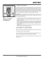
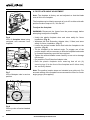
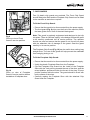
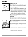
®
710W Corded Jigsaw
With Variable Speed Control
Original
Instruction
Manual
Read instructions before operating tools
Models manual is applicable to:
Rage7-S 230V UK (075-0001)
RAGE7-S 110V UK (075-0002)
RAGE7-S 230V EU (075-0003)
RAGE7-S 120V US (075-0004)
RAGE7-S blades (075-0200)
PUBLISHED DATE: 01.12.12
®
TABLE OF CONTENTS
Important Information....................................... 03
Evolution Limited Guarantee............................ 03
General Safety Rules....................................... 03
Additional Specific Safety Rules....................... 05
Labels & Symbols............................................. 07
Specification..................................................... 07
Jigsaw Overview.............................................. 08
Operating Instructions...................................... 09
Cutting Advice.................................................. 15
Maintenance..................................................... 16
Environmental Protection................................. 16
EC - Declaration of Conformity......................... 17
A parts diagram is available online at:
www.evolutionpowertools.com
This instruction manual was
originally written in English.
2
www.evolutionpowertools.com
®
IMPORTANT
Please read these operating and
instructions carefully and completely.
safety
For your own safety, if you are uncertain about
any aspect of using this equipment please access
the relevant Technical Helpline, the number of
which can be found on the Evolution Power Tools
website. We operate several Helplines throughout
our worldwide organization, but technical help is
also available from your supplier.
WEBSITE
www.evolutionpowertools.com/register
Congratulations on your purchase of an
Evolution Power Tools Machine. Please
complete your product registration ‘online’
as explained in the A5 online guarantee
registration leaflet included with this machine.
You can also scan the QR code found on the
A5 leaflet with a Smart Phone. This will enable
you to validate your machine’s guarantee
period via Evolution’s website by entering
your details and thus ensure prompt service
if ever needed. We sincerely thank you for
selecting a product from Evolution.
EVOLUTION LIMITED GUARANTEE
Evolution Power Tools reserves the right to make
improvements and modifications to the product
design without prior notice.
Please refer to the guarantee registration leaflet
and/or the packaging for details of the terms,
conditions and period of the guarantee.
Evolution Power Tools will, within the guarantee
period, and from the original date of purchase,
repair or replace any goods found to be defective in
materials or workmanship. This guarantee is void if
the tool being returned has been used beyond the
recommendations in the Instruction Manual or if the
machine has been damaged by accident, neglect,
or improper service. This guarantee does not apply
to machines and / or components which have
been altered, changed, or modified in any way, or
subjected to use beyond recommended capacities
and specifications. Electrical components are
subject to respective manufacturers’ warranties.
All goods returned defective shall be returned
prepaid freight to Evolution Power Tools. Evolution
Power Tools reserves the right to optionally repair or
replace it with the same or equivalent item. There
is no warranty – written or verbal – for consumable
accessories such as (following list not exhaustive)
blades, cutters, drills, chisels or paddles etc. In no
event shall Evolution Power Tools be liable for loss
or damage resulting directly or indirectly from the
use of our merchandise or from any other cause.
Evolution Power Tools is not liable for any costs
incurred on such goods or consequential damages.
No officer, employee or agent of Evolution Power
Tools is authorized to make oral representations of
fitness or to waive any of the foregoing terms of sale
and none shall be binding on Evolution Power Tools.
Questions relating to this limited guarantee
should be directed to the company’s head
office, or call the appropriate Helpline number.
POWER TOOL GENERAL
SAFETY INSTRUCTIONS
(These General Power Tool Safety Instructions
are as specified in BS EN 60745-1:2009 & EN
61029-1:2009)
WARNING:
Read all safety warnings and instructions.
Failure to follow the warnings and instructions may
result in electric shock, fire and/ or serious injury.
Save all warnings and
instructions for future reference.
The term “power tool” in the warnings refers to
your mains-operated (corded) power tool or
battery-operated (cordless) power tool.
1) General Power Tool Safety Warnings
[Work area safety]
a) Keep work area clean and well lit.
Cluttered or dark areas invite accidents.
b) Do not operate power tools in explosive
atmospheres, such as in the presence of
flammable liquids, gasses or dust. Power tools
create sparks which may ignite the dust or fumes.
c) Keep children & bystanders away while
operating power tool. Distractions can cause
you to lose control.
www.evolutionpowertools.com
3
®
2) General Power Tool Safety Warnings
[Electrical Safety]
a) Power tool plugs must match the outlet.
Never modify the plug in any way. Do not use
any adapter plugs with earthed (grounded)
power tools. Unmodified plugs and matching
outlets will reduce the risk of electric shock.
b) Avoid body contact with earthed or
grounded surfaces, such as pipes, radiators,
ranges and refrigerators. There is an increased
risk of electric shock if your body is earthed or
grounded.
c) Do not expose power tools to rain or wet
conditions. Water entering a power tool will
increase the risk of electric shock.
d) Do not abuse the cord. Never use the cord
for carrying, pulling or unplugging the power
tool. Keep cord away from heat, oil, sharp
edges or moving parts. Damaged or entangled
cords increase the risk of electric shock.
e) When operating a power tool outdoors, use
an extension cord suitable for outdoor use.
Use of a cord suitable for outdoor use reduces
the risk of electric shock.
f) If operating a power tool in a damp location
is unavoidable, use a residual current device
(RCD) protected supply. Use of an RCD reduces
the risk of electric shock.
3) General Power Tool Safety Warnings
[Personal Safety].
a) Stay alert, watch what you are doing and
use common sense when operating a power
tool. Do not use a power tool while you are
tired or under the influence of drugs, alcohol
or medication. A moment of inattention while
operating power tools may result in serious
personal injury.
b) Use personal protective equipment. Always
wear eye protection. Protective equipment such
as dust masks, non-skid safety shoes, hard hat or
hearing protection used for appropriate conditions
will reduce personal injuries.
c) Prevent unintentional starting. Ensure the
switch is in the off-position before connecting
to power source and or battery pack, picking
up or carrying the tool. Carrying power tools with
your finger on the switch or energising the power
tools that have the switch on invites accidents.
4
d) Remove any adjusting key or wrench before
turning the power tool on. A wrench or key left
attached to a rotating part of a power tool may
result in personal injury.
e) Do not overreach. Keep proper footing and
balance at all times. This enables better control
of the power tool in unexpected situations.
f) Dress properly. Do not wear loose clothing or
jewellery. Keep your hair, clothing and gloves
away from moving parts. Loose clothes, jewellery
or long hair can be caught in moving parts.
g) If devices are provided for the connection of
dust extraction and collection facilities, ensure
that these are connected and properly used.
Use of dust collection can reduce dust-related
hazards.
4) General Power Tool Safety Warnings
[Power tool use and care].
a) Do not force the power tool. Use the correct
power tool for your application. The correct
power tool will do the job better and safer at a rate
for which it was designed.
b) Do not use the power tool if the switch does
not turn it on or off. Any power tool that cannot
be controlled with the switch is dangerous and
must be repaired.
c) Disconnect the power tool from the power
source and/or battery pack from the power
tool before making any adjustments, changing
accessories, or storing power tools. Such
preventative safety measures reduce the risk of
starting the power tool accidentally.
d) Store idle power tools out of the reach of
children and do not allow persons unfamiliar
with the power tool or these Instructions
to operate the power tool. Power tools are
dangerous in the hands of untrained users.
e) Maintain power tools. Check for
misalignment or binding of moving parts,
breakage of moving parts and any other
condition that may affect the power tools
operation. If damaged, have the power tool
repaired before use. Many accidents are caused
by poorly maintained power tools.
f) Keep cutting tools sharp and clean. Properly
maintained cutting tools with sharp cutting edges
are less likely to bind and are easier to control.
www.evolutionpowertools.com
®
g) Use the power tool, accessories and tool
bits etc. in accordance with these instructions,
taking into account the working conditions
and the work to be performed. Use of the power
tool for operations different from those intended
could result in a hazardous situation.
5) General Power Tool Safety Warnings
[Service]
a) Have your power tool serviced by a
qualified repair person using only identical
replacement parts. This will ensure that the
safety of the power tool is maintained.
OUTDOOR USE
WARNING: For your protection if this tool is to be
used outdoors it should not be exposed to rain,
or used in damp locations. Do not place the tool
on damp surfaces. Use a clean, dry workbench
if available. For added protection use a residual
current device (R.C.D.) that will interrupt the
supply if the leakage current to earth exceeds
30mA for 30ms. Always check the operation of
the residual current device (R.C.D.) before using
the machine.
If an extension cable is required it must be a
suitable type for use outdoors and so labelled.
The manufacturers instructions should be
followed when using an extension cable.
HEALTH ADVICE
WARNING: When drilling, sanding, sawing or
grinding, dust particles will be produced. In some
instances, depending on the materials you are
working with, this dust can be particularly harmful
to you (e.g. lead from old gloss paint).You are
advised to consider the risks associated with the
materials you are working with and to reduce
the risk of exposure. Some wood and wood
type products, especially MDF (Medium Density
Fibreboard), can produce dust that may be
hazardous to your health. We recommend the use
of an approved face mask with replaceable filters
when using this machine, in addition to using the
dust extraction facility.
You should always:
• Work in a well-ventilated area.
• Work with approved safety equipment, such as
dust masks that are specially designed to filter
microscopic particles.
WARNING: If you suspect that paint on surfaces
in your home contains lead, seek professional
advice. Lead based paints should only be removed
by a professional and you should not attempt
to remove it yourself. Once the dust has been
deposited on surfaces, hand to mouth contact can
result in the ingestion of lead. Exposure to even
low levels of lead can cause irreversible brain and
nervous system damage. The young and unborn
children are particularly vulnerable.
ADDITIONAL SAFETY RULES FOR YOUR
EVOLUTION JIGSAW
1. Do not expose to rain or water.
2. Wear hearing protection when necessary.
Exposure to noise can cause hearing loss.
3. Cutting/scraping blades and accessories
can become very hot. Take care when changing
or handling any bits or accessories.
4. Hold the tool by the insulated gripping
surfaces, especially when performing an
operation where the blade may contact hidden
wiring. If the blade contacts a ‘live’ wire, exposed
metal parts of the power tool could become ‘live’
and give the operator an electric shock.
5. If possible, use clamps or a vice to hold
your work.
6. When cutting into walls, floors or similar
areas, make sure, as far as possible, that there
are no services (gas or water pipes, electric
cables etc) in the path of the blade. Striking
hidden services could cause injury to the user and
damage to the property.
7. Always disconnect the jigsaw from the
power supply before changing the blade.
Never use damaged or distorted blades.
8. Always allow the saw to come to a complete halt
before putting it down. A running tool may bounce
uncontrollably if the blade tip contacts any surface.
9. Always consider the work environment
and wear the appropriate personal protection
equipment. This could include dust masks, eye
protection, safety footwear etc.
www.evolutionpowertools.com
5
®
WARNING: the operation of any power tool can
result in foreign objects being thrown towards
your eyes, which could result in severe eye
damage. Before beginning power tool operation,
always wear safety goggles or safety glasses with
side shield or a full face shield where needed.
WARNING: If any parts are missing, do not
operate your machine until the missing parts are
replaced. Failure to follow this rule could result in
serious personal injury.
INTENDED USE OF THIS POWER TOOL
WARNING: This product is a Multipurpose Jigsaw
and has been designed to be used with special
Evolution multipurpose blades. Only use blades
designed for use in this machine and/or those
recommended specifically by Evolution Power
Tools Ltd.
When fitted with a correct blade
this machine can be used to cut:
• Wood
• Wood Derived Products
(MDF, Chipboard, Plywood,
Blockboard, Hardboard. etc)
• Aluminium
• Mild Steel
VIBRATION
WARNING: When using this machine the
operator can be exposed to high levels of vibration
transmitted to the hand and arm. It is possible that
the operator could develop “Vibration white finger
disease” (Raynaud syndrome). This condition can
reduce the sensitivity of the hand to temperature
as well as producing general numbness.
Prolonged or regular users of sanding machines
should monitor the condition of their hands and
fingers closely. If any of the symptoms become
evident, seek immediate medical advice.
• The measurement and assessment of human
exposure to hand-transmitted vibration in the
workplace is given in: BS EN ISO 5349-1:2001
and BS EN ISO 5349-2:2002.
• Many factors can influence the actual vibration
level during operation e.g. the work surfaces
condition and orientation and the type and
condition of the saw blade being used. Before
each use, such factors should be assessed,
and where possible appropriate working
practices adopted. Managing these factors can
help reduce the effects of vibration:
Handling
PROHIBITED USE OF THIS POWER TOOL
WARNING: This product is a Multipurpose Jigsaw
and must only be used as such. It must not be
modified in any way, or used to power any other
equipment or drive any other accessories other
than those mentioned in this Instruction Manual.
WARNING: This machine is not intended for
use by persons (including children) with reduced
physical, sensory or mental capabilities, or lack
of experience and knowledge, unless they have
been given supervision or instruction concerning
the safe use of the machine by a person
responsible for their safety.
• Handle the machine with care, allowing the
machine to do the work.
• Avoid using excessive physical effort on any of
the machines controls.
• Consider your security and stability, and the
orientation of the machine during use.
Work Surface
• Consider the work surface material; its condition,
density, strength, rigidity and orientation.
Children should be supervised to ensure that they
do not have access to, and are not allowed to play
with, this machine.
6
www.evolutionpowertools.com
®
LABELS & SYMBOLS
Jigsaw SPECIFICATION
WARNING: Do not operate machine if warning
and/or instruction labels are missing or damaged.
Contact Evolution Power Tools or your supplier for
replacement labels.
Motor
230V ~ 50Hz............................................ 710W (6A)
110V ~ 60Hz......................................... 600W (5.2A)
Note: All or some of the following symbols may
appear in the manual or on the product.
Symbol
Description
V
Volts
A
Amperes
Hz
Hertz
RPM No Load........................ 0 - 3000min-1 (rpm)
Recommended Max Duty Cycle.............30mins
Stroke Length.....................................26mm (1”)
Cutting Capacity
Wood............................................80mm (3-3/16”)
Metal..................................................8mm (5/16”)
Speed
Insulation Class................................................ II
~
Alternating Current
no
No Load Speed
Weight (Gross)..................................4.1kg (9lbs)
Min
-1
Wear Safety Goggles
Wear Ear Protection
Do Not Touch
Keep Hands Away
Wear Dust Protection
Restriction of Hazardous
Substances Directive
CE certification
Waste Electrical &
Electronic Equipment
Read Manual
Warning
Laser Warning
Noise & Vibration Data
Sound Pressure LPA............... 87dB(A) K=3dB(A)
Sound Power Level LWA......... 98dB(A) K=3dB(A)
Vibration Level....................3:129 m/s2 K=1.5m/s2
Note: The vibration measurement was made
under standard conditions in accordance with:
BS EN 610291.2009.
WARNING: The vibration emission during actual
use of the power tool can differ from the declared
total value depending on the ways in which the
tool is used. The need to identify safety measures
and to protect the operator are based on an
estimation of exposure in the actual conditions of
use (taking account of all parts of the operating
cycle, such as the times the tool is switched off,
when it is running idle, in addition to trigger time)
ITEMS SUPPLIED
Instruction Manual..........................................1 pc
Hex Key 4mm.................................................1 pc
Footplate Shoe...............................................1 pc
Jigsaw Blades............................................1 pack
Parallel Edge Guide.......................................1 pc
Dust Extraction Adaptor..................................1 pc
Chip Guard (Front).........................................1 pc
Chip Guard (Footplate)...................................1 pc
Batteries ‘AAA’ ...............................................2 pc
www.evolutionpowertools.com
7
®
JIGSAW OVERVIEW
3
2
4
6
7
8
5
10
9
1
8
1
Cutting Blade
6
Laser Switch
2
Trigger Switch
7
Dust Extraction
3
Locking Button
8
Chip Guard
4
Rotary Control
9
Parallel Edge Guide
5
Cutting Action Selection Switch
10
Air Blower
www.evolutionpowertools.com
®
OPERATION
1. INSTALLING OR REMOVING A BLADE (Fig. 1)
WARNING: The jigsaw must be disconnected from the power
supply and the blade must not be facing the operator when installing
or removing the blade.
Installation:
Fig 1
Close up view of the quick fit/
release chuck with the blade
inserted.
• Check that the jigsaw blade is of the correct type.
• Insert the blade into the chuck ensuring that the blade teeth face
forwards.
• Rotate the chuck locking collar forward and slide the jigsaw blade
fully ‘home’ into the chuck. Ensure that the ‘T’ bar of the bayonet
fitting is fully engaged within the chuck. (Fig. 1)
• Release the chuck locking collar.
• Check to ensure the blade is securely gripped by the chuck.
• Check to ensure that the back of the blade has engaged into the
groove in the guide roller. (Fig. 2)
Removal:
Note: A recently used blade can be very hot. Allow such a blade to
cool down before attempting to remove it from the machine.
Fig 2
Close up view of the correctly
fitted blade with the back of the
blade engaged into the groove
in the guide roller.
• Disconnect the machine from the power supply.
• Set the Cutting Action. Selection Switch to position 0.
• Rotate the chuck locking collar forwards.
The blade will automatically eject from the machine.
Note: The blade may eject from the chuck with some force. Ensure
that the ejecting blade will not strike any nearby surface, bystander
or animal. If possible eject a used blade directly into a scrap
recycling bin.
2. ON/OFF TRIGGER SWITCH (Fig. 3a)
2
This tool is fitted with a variable speed Trigger Switch that delivers
higher speed as the trigger pressure is increased.
EXPLANATION OF Fig. 3a NUMBERS:
1
3
Fig 3 (a)
Close up view of Trigger
Switch, Locking Button
and Rotary Control.
1 = TRIGGER SWITCH
2 = LOCKING BUTTON
3 = ROTARY CONTROL
www.evolutionpowertools.com
9
®
The Trigger Switch is also fitted with a rotary control (Fig 3b) that
allows the operator to select a constant speed and then lock the
trigger in this position.
3. TRIGGER SWITCH LOCKING BUTTON (Fig. 3c)
Fig 3 (b)
Close up view
of Rotary Control.
• Pull the trigger fully and rotate the rotary control until the desired
speed is obtained.
• Push in the speed locking button to lock the trigger at the selected
speed.
• Press the trigger switch gently and then release to disengage the
selected speed and to switch the machine off.
4. CUTTING ACTION SELECTION SWITCH (Fig. 4)
This jigsaw has a 4 position switch (0-3) located on the Left Hand
side of the machine just behind the blade. Only operate this switch
when the machine is switched ‘Off’ and the blade is stationary.
Position ‘0’
Straight cutting action
Positions ‘1 – 3’ Orbital cutting actions
Orbital cutting action has an aggressive blade cutting motion and is
especially suited for cutting soft materials.
During orbital cutting the blade moves forwards as well as up and
down. Position 1 is the least aggressive of the orbital cutting actions,
with position 3 being the most aggressive.
Fig 3 (c)
Close up view
Locking Button.
The Table below gives some typical examples of the use of the
orbital cutting facility. We recommend that the operator always
practices on a piece of unwanted material to determine the most
suitable selection for the task at hand.
POSITION
TYPICAL APPLICATION
0
Thin materials. Fine cuts. Tight curves. All metals.
1
Hard materials such as chipboard, MDF, Plywood etc.
2
Thick materials such as constructional timber and plastic.
3
Fast cuts when cutting with the grain in softwood material.
Fig 4
Close up view of
Selection Switch Lever.
10
www.evolutionpowertools.com
®
5. LASER CUTTING GUIDE
This jigsaw is fitted with a Laser Guide which can be useful when
cutting straight lines. Only switch the Laser Guide on when you are
about to make a straight cut, and switch it off when the cut has been
completed. The switch is located on the front of the machine. Press
the ‘I’ side of the rocker switch to turn the Laser Guide ‘On’. Press
the ‘O’ side of the rocker switch to turn the Laser Guide ‘Off’.
WARNING: Do not stare directly at the laser beam. A hazard may
exist if you deliberately stare into the beam. Please observe all of
the following safety rules.
Fig 5
Close up view of battery
compartment cover
and fixing screw.
• The laser beam must not be deliberately aimed at personnel and
must be prevented from being directed towards the eyes of a
person or animal.
• Always ensure that the laser beam is used only on workpieces that
have non-reflective surfaces, i.e natural wood or matt surfaces etc.
• Never exchange the laser module assembly for a different type or
class of laser.
• Repairs to the laser module must only be conducted by Evolution
Power Tools or their authorized agent.
REPLACEMENT OF LASER BATTERIES
Power for the Laser Guide is provided by two (2) ‘AAA’ Cells. When
exhausted these should be replaced.
Access to the battery compartment is gained by loosening the screw
and removing the battery compartment cover. (Fig. 5)
Observe the polarity of the cells and replace the cover after cell
replacement.
www.evolutionpowertools.com
11
®
6. FOOTPLATE ANGLE ADJUSTMENT
Note: The footplate is factory set and adjusted so that the blade
cuts at 900 to the footplate.
The footplate may be tilted to an angle of up to 450 to either side with
positive location stops at 150, 300 and 450.
To adjust the footplate:
WARNING: Disconnect the jigsaw from the power supply before
attempting to adjust the footplate.
Fig 6
View of footplate shoe being
unclipped and removed from
footplate.
Fig 7
View of Adaptor tube in service
position.
• Unclip the plastic footplate shoe and store safely for future
installation. (Fig. 6)
• Withdraw the Dust Extraction Adaptor tube, if fitted, and store
safely for future installation. (Fig. 7)
• Loosen the socket headed screw that holds the footplate to the
machine. (Fig. 8)
• Tilt the footplate to the desired angle. To engage one of the
positive stops it will be necessary to slide the footplate backwards
or forwards depending upon the stop required.
• Tighten the socket-headed screw carefully so as not to damage
the threads.
• Re-install the Dust Extraction Adaptor tube.
• Refit the plastic footplate shoe ensuring that all six (6)
securing lugs (2 to the front of the footplate and 2 either side)
are correctly seated.
Note: The positive location stops are intended as a guide only. For
accurate setting of the footplate we recommend the use of a vernier
angle gauge (not supplied).
Fig 8
Close up view of socket headed
screw.
12
www.evolutionpowertools.com
®
7. CHIP GUARDS
Two (2) plastic chip guards are provided. The Front Chip Guard
should always be fitted and the Footplate Chip Guard can be fitted
to the machine as and when required.
To fit the Front Chip Guard:
• Ensure that the machine is disconnected from the power supply
• The front guard (Fig. 9) clips over the front of the machine, below
the laser guide and in front of the steel blade guard.
Fig 9
Close up view of Front
Guard in service position.
Note: This guard is precisely engineered and designed to just clip
into place. There is sufficient ‘spring’ in the design to allow the guard
to be carefully positioned into its service position. The operator
should use care and ensure that the guard is not ‘forced’ into place
with the attendant risk of damage to the guard. Seat the guard
carefully in its service position.
The Footplate Chip Guard (Fig. 10) can be useful when cutting long
straight lines. The use of this guard will help prevent the sawblade
from swinging during a cut.
To fit the Footplate Chip Guard:
Fig 10
Close up view of Footplate
Guard in service position before
installation of footplate shoe.
• Ensure that the machine is disconnected from the power supply.
• Unclip the plastic Footplate Shoe from the Footplate.
• Clip the Footplate Chip Guard into the inside of the Footplate
Shoe with the ‘Vee’ pointing towards the rear of the shoe, and the
raised platform positioned within the throat of the shoe. Ensure
positive location within the shoe. The guard should lie ‘flush’ with
both surfaces of the shoe.
• Carefully replace the Footplate Shoe with the attached Chip
Guard onto the Footplate.
www.evolutionpowertools.com
13
®
8. PARALLEL EDGE GUIDE
The supplied Parallel Edge Guide can be fitted to either side of the
machine. It can be a useful aid when cutting straight lines that are
parallel to an existing edge.
To fit the Parallel Edge Guide:
Clamp
Fig 11
Parallel Edge Guide.
• Loosen the cross-head screw found in the Parallel Edge Guide
clamp and slide the clamp from the arm of the guide.
• Locate the clamp in the required service position on either the
right or left hand side of the machines footplate just ahead of the
blade. (Fig. 11).
• Slide the arm of the Parallel Edge Guide through the clamp and
through the two (2) rectangular slots in the footplate.
• Set the Edge Guide at the required distance and then tighten the
cross-head screw to lock the Edge Guide securely in place.
Note: The Front Chip Guard can be fitted to this machine when the
Parallel Edge Guide is fitted.
9. AIR BLOWER
This Jigsaw is equipped with an Air Blower. This can be used to
blow away dust created by the blade from the cutting area thereby
keeping the cutting line(s) clear and visible.
Note: We recommend that the Air Blower is used in conjunction with
a suitable workshop dust extraction machine connected to the Dust
Extraction Adaptor of the jigsaw.
We recommend that the Air Blower is not used when cutting metal or
when cutting materials that require a lubricant. Mechanical vacuum
dust extraction using the Adaptor tube will always work better with
the Air Blower turned ‘OFF’.
To switch the Air Blower ‘ON’:
Fig 12
Close up view of Air
Blower Slide control lever.
14
• Push the ‘Air Blower’ control slide fully to the right (as seen from
the operators viewpoint) (Fig 12)
To switch the Air Blower ‘OFF’:
• Push the ‘Air Blower’ control slide fully to the left.
www.evolutionpowertools.com
®
10. DUST EXTRACTION
This jigsaw is fitted with a Dust Extraction Adaptor tube. (Fig. 13)
Whenever possible it is good practice to connect the Adaptor tube
to a workshop dust extraction machine. The Air Blower should be in
the ‘OFF’ position.
During operations the use of a dust extraction machine will help
keep the workplace clean and dust free, enhancing operator safety
and comfort and aiding operator cutting accuracy.
Fig 13
Close up view of adaptor tube
with vacuum hose about to be
connected.
CUTTING ADVICE
Note: Always ensure that the footplate of the jigsaw is in close
contact with the workpiece throughout the cutting procedure. If the
footplate is allowed to ‘lift’ away from the workpiece operator control
and accuracy will be compromised.
• Clearly mark out the cutting line to be followed on the workpiece
(use a pencil or other suitable marking device).
• Small workpieces should be secured in a vice or clamped to a
workbench. Check that the passage of the blade is not obstructed.
• Larger workpieces should be clamped to sawhorses or similar.
Check that the passage of the blade is not obstructed.
• Set the Cutting Action Selection Lever to the desired position.
• Align the saw with the cutting line and rest the front of the footplate
on the workpiece.
Note: Ensure that the blade is not in contact with the workpiece at
this stage.
• Switch the machine ‘On’ and gently feed the jigsaw into the
workpiece. Be careful to hold the jigsaw firmly and keep full
control as the blade contacts the workpiece.
• Adjust the speed of the blade as necessary to achieve optimum
cutting performance.
• Use the Laser guide if necessary, but only on non-reflective
materials.
Note: Do not force the blade. Let the blade do the work by adjusting
the speed and feed rates to achieve best performance.
www.evolutionpowertools.com
15
®
CUTTING METAL
ANGLED CUTTING
When cutting any metal a suitable cutting
lubricant/coolant should be used. Cast Iron and
Brass can be cut without a cutting lubricant.
Always use a blade that is capable of cutting
metal, and secure the workpiece securely, if
practicable, in a vice or similar clamping device.
Angled cutting, whatever the material, is always
more difficult than general straight cutting. With
angled cutting it is very important to allow the saw
blade to do the work. Do not ‘force’ the blade. A
trial run on unwanted material to determine the
best combination of blade feed and speed is
recommended.
WARNING: When cutting metal the Cutting Action
Selection Lever must be set to the ‘0’ position.
Return to the factory setting when angled cutting
is completed. Recheck the security of the blade.
CUTTING CIRCLES OR CURVES
BLADES
When cutting curves, particularly tight curves,
start with a reasonably slow speed, and gradually
increase the speed until the optimum performance
is achieved. Do not force the blade, as in curved
cutting this can lead to the blade deflection, and
possible blade breakage.
Choose blades carefully. Use only a blade that is
suitable for this machine and for the material to
be cut.
To cut a circle from a workpiece:
• Mark out the circle in the required postion.
• Drill a ø12 mm hole near the centre of the circle.
• Insert the jigsaw blade into the ø12 mm hole.
Ensure that there is clearance between the
blade and the workpiece.
• Begin cutting towards the outside of the circle,
slowly in a spiral fashion, until the blade is
following the required cutting line.
• Advance the jigsaw slowly to avoid cutting a
slanted surface or experiencing blade deflection.
The ability of any jigsaw to follow curves, provide
smooth finishes or faster cutting is directly related
to the type of blade employed.
MAINTENANCE
Your Evolution Jigsaw requires no major additional
lubrication or maintenance. Occasionally apply
a drop of light machine oil to the blade guide
spindle. There are no user serviceable parts in
your Evolution Jigsaw.
Keep the tool clean, but do not use chemical
cleaners which may damage the plastic parts.
Clean with a dry cloth. Ensure that the motor
ventilation slots are kept clean.
ENVIRONMENTAL PROTECTION
Waste electrical products should not be disposed
of with household waste. Please recycle where
facilities exist. Check with your Local Authority or
retailer for recycling advice.
16
www.evolutionpowertools.com
®
EC DECLARATION OF CONFORMITY
In accordance with EN ISO 17050-1:2004
The manufacturer of the product covered by this Declaration is:
Evolution Power Tools, Venture One, Longacre Close, Holbrook Industrial Estate, Sheffield, S20 3FR
The manufacturer hereby declares that the machine as detailed in this declaration fulfils all the
relevant provisions of the Machinery Directive and other appropriate directives as detailed below. The
manufacture further declares that the machine as detailed in this declaration, where applicable, fulfils
the relevant provisions of the Essential Health and Safety requirements.
The Directives covered by this Declaration are as detailed below:
2006/42/EC
2004/108/EC
93/68/EC
2002/95/EC
2002/96/EC
Machinery Directive
Electromagnetic Compatibility Directive
The CE Marking Directive
The Restriction of the Use of certain Hazardous Substances in Electrical Equipment (RoHS) Directive
As amended by 2003/108/EC. The Waste Electrical and Electronic Equipment (WEEE) Directive
And is in conformity with the applicable requirements of the following documents
EN 60745-1:2009+A11:2010
EN 60825-1:2007
EN 60745-2-3:2011
EN55014-1:2006/+A1:2009
EN 55014-2:1997/+2001/+A2:2008
EN 61000-3-2:2006/+A1:2009/+A2:2009
EN 61000-3-3:2008
Product Details
Description: Evolution Model No: Factory Model No: Brand Name: Voltage: Input: RAGE7-S 710W Corded Jigsaw With Variable Speed Control
Rage7-S2 (075-0001) / RAGE7-S1 (075-0002) / RAGE7-S2EU (075-0003)
HDA1110
EVOLUTION
110V / 230V
50HZ / 60HZ
The technical documentation required to demonstrate that the product meets the requirements of directive has been
compiled and is available for inspection by the relevant enforcement authorities, and verifies that our technical file
contains the documents listed above and that they are the correct standards for the product as detailed above.
Name and address of technical documentation holder.
Signed:
Print: Steven Bulloss: Operations Director
Signed: Print: Lettie Lui: Product Manager
Year that CE was first applied
12
Date: 01/12/12
www.evolutionpowertools.com
17
®