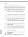
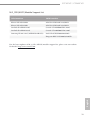
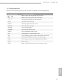
1
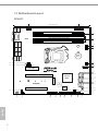
Z97M WS
C226M WS
User Manual
Version 1.0
Published June 2014
Copyright©2014 ASRock Rack INC. All rights reserved.
Version 1.0
Published June 2014
Copyright©2014 ASRock Rack Inc. All rights reserved.
Copyright Notice:
No part of this documentation may be reproduced, transcribed, transmitted, or translated
in any language, in any form or by any means, except duplication of documentation by the
purchaser for backup purpose, without written consent of ASRock Rack Inc.
Products and corporate names appearing in this documentation may or may not be
registered trademarks or copyrights of their respective companies, and are used only for
identiication or explanation and to the owners’ beneit, without intent to infringe.
Disclaimer:
Speciications and information contained in this documentation are furnished for
informational use only and subject to change without notice, and should not be
constructed as a commitment by ASRock Rack. ASRock Rack assumes no responsibility
for any errors or omissions that may appear in this documentation.
With respect to the contents of this documentation, ASRock Rack does not provide
warranty of any kind, either expressed or implied, including but not limited to the implied
warranties or conditions of merchantability or itness for a particular purpose.
In no event shall ASRock Rack, its directors, oicers, employees, or agents be liable for
any indirect, special, incidental, or consequential damages (including damages for loss of
proits, loss of business, loss of data, interruption of business and the like), even if ASRock
Rack has been advised of the possibility of such damages arising from any defect or error
in the documentation or product.
his device complies with Part 15 of the FCC Rules. Operation is subject to the following
two conditions:
(1) this device may not cause harmful interference, and
(2) this device must accept any interference received, including interference that
may cause undesired operation.
CALIFORNIA, USA ONLY
he Lithium battery adopted on this motherboard contains Perchlorate, a toxic substance
controlled in Perchlorate Best Management Practices (BMP) regulations passed by the
California Legislature. When you discard the Lithium battery in California, USA, please
follow the related regulations in advance.
“Perchlorate Material-special handling may apply, see www.dtsc.ca.gov/hazardouswaste/
perchlorate”
ASRock Rack’s Website: www.ASRockRack.com
Contact Information
If you need to contact ASRock Rack or want to know more about ASRock Rack,
you’re welcome to visit ASRock Rack’s website at www.ASRockRack.com; or you
may contact your dealer for further information.
ASRock Rack Incorporation
6F., No.37, Sec. 2, Jhongyang S. Rd., Beitou District,
Taipei City 112, Taiwan (R.O.C.)
Contents
Chapter 1 Introduction ................................................................1
1.1 Package Contents ........................................................................................... 1
1.2 Speciications ................................................................................................... 2
1.3 Unique Features .............................................................................................. 5
1.4 Motherboard Layout ..................................................................................... 6
1.5 I/O Panel ............................................................................................................ 9
1.6 Block Diagram................................................................................................ 10
Chapter 2 Installation.................................................................11
2.1 Screw Holes .................................................................................................... 11
2.2 Pre-installation Precautions ..................................................................... 11
2.3 Installing the CPU ......................................................................................... 12
2.4 Installing the CPU Fan and Heatsink ..................................................... 14
2.5 Installation of Memory Modules (DIMM)............................................. 15
2.6 Expansion Slots (PCI Express Slots) ........................................................ 17
2.7 Onboard Headers and Connectors ........................................................ 19
2.8 Dr. Debug ........................................................................................................26
2.9 Driver Installation Guide ............................................................................ 27
2.10 Dual LAN and Teaming Operation Guide ..........................................28
2.11 M.2_SSD (NGFF) Module Installation Guide .....................................29
Chapter 3 UEFI Setup Utility .................................................... 32
3.1 Introduction.................................................................................................... 32
3.1.1 UEFI Menu Bar ........................................................................................................................32
3.1.2 Navigation Keys ....................................................................................................................33
3.2 Main Screen ....................................................................................................34
3.3 OC Tweaker Screen (only for Z97M WS motherboard) ................................ 35
3.3.1 CPU Coniguration ..............................................................................................................35
3.3.2 DRAM Timing Coniguration.......................................................................................... 38
3.3.3 FIVR Coniguration ..............................................................................................................43
3.3.4 Voltage Coniguration ...................................................................................................... 44
3.4 Advanced Screen..........................................................................................45
3.4.1 CPU Coniguration ............................................................................................................. 46
3.4.2 Chipset Coniguration ..................................................................................................... 48
3.4.3 Storage Coniguration ......................................................................................................51
3.4.4 Intel® Rapid Start Technology ........................................................................................53
3.4.5 Intel® Smart Connect Technology............................................................................... 54
3.4.6 Intel® Thunderbolt .............................................................................................................55
3.4.7 Super IO Coniguration.................................................................................................... 56
3.4.8 ACPI Coniguration.............................................................................................................57
3.4.9 USB Coniguration ..............................................................................................................59
3.4.10 Serial Port Console Redirection ..................................................................................61
3.4.11 AMT Coniguration (only supported for C226M WS motherboard) ....................................63
3.5 Tools ................................................................................................................65
3.6 H/W Monitor Screen.....................................................................................66
3.7 Boot Screen .....................................................................................................68
3.8 Security Screen .............................................................................................. 71
3.9 Event Logs ........................................................................................................72
3.10 Exit Screen .................................................................................................... 74
Chapter 4 Software Support.................................................... 75
4.1 Install Operating System ........................................................................... 75
4.2 Support CD Information ............................................................................ 75
4.2.1 Running The Support CD ................................................................................................75
4.2.2 Drivers Menu ........................................................................................................................75
4.2.3 Utilities Menu .......................................................................................................................75
4.2.4 Contact Information ..........................................................................................................75
Chapter 5 Troubleshooting ...................................................... 76
5.1 Troubleshooting Procedures .................................................................... 76
5.2 Technical Support Procedures ................................................................78
5.3 Returning Merchandise for Service .......................................................78
Z97M WS / C226M WS
Chapter 1 Introduction
hank you for purchasing ASRock Rack Z97M WS / C226M WS motherboard, a
reliable motherboard produced under ASRock Rack’s consistently stringent quality
control. It delivers excellent performance with robust design conforming to ASRock
Rack’s commitment to quality and endurance.
In this manual, chapter 1 and 2 contains introduction of the motherboard and stepby-step guide to the hardware installation. Chapter 3 and 4 contains the coniguration
guide to BIOS setup and information of the Support CD.
Because the motherboard speciications and the BIOS sotware might be updated, the content of this manual will be subject to change without notice. In case any modiications of
this manual occur, the updated version will be available on ASRock Rack website without
further notice. You may ind the latest memory and CPU support lists on ASRock Rack
website as well. ASRock Rack’s Website: www.ASRockRack.com
If you require technical support related to this motherboard, please visit our website for
speciic information about the model you are using.
www.asrock.com/support/index.asp
1.1 Package Contents
• ASRock Rack Z97M WS / C226M WS Motherboard
(ATX Form Factor: 9.6-in x 9.6-in, 24.4 cm x 24.4 cm)
• 4 x SATA3 Cables (50cm)
• 2 x SATA3 Cables (60cm)
• 1 x Screw for M.2_SSD (NGFF) Socket 3
• 1 x I/O Shield
• Support CD
• User Manual
English
If any items are missing or appear damaged, contact your authorized dealer.
1
1.2 Speciications
Z97M WS / C226M WS
MB Physical Status
Form Factor
micro ATX
Dimension
9.6'' x 9.6'' (24.4 cm x 24.4 cm)
Processor System
CPU
C226M WS:
- Supports Intel® Xeon® processor E3-1200 v3 product family
& Haswell i3
*Haswell i5/i7 processor support is an extended advantage provided by
ASRock Rack. It is out of warranty; user's discretion is required.
** HDMI only works with certain Intel® E3 v3 CPUs(E3-1276 v3 /E3-1246 v3 /
E3-1226v3 /E3-1275L v3 /E3-1286 v3/E3-1286L v3
Socket
Chipset
System Memory
Capacity
Type
Z97M WS:
- Supports 4th Gen & 5th Generation Intel® Core™ Processors
(Socket 1150)
- Supports Intel® K-Series CPU
- Supports Intel® Turbo Boost 2.0 Technology
Single socket H3 (LGA1150)
Intel® Z97 / C226
- 4 x 240-pin DDR3 DIMM slots
- Support up to 32GB, un-bufered DIMM
- Dual Channel DDR3 1600/1333 UDIMM
C226M WS:
- Supports DDR3 1600/1333
Z97M WS:
- Supports DDR3 2400+(OC)/2133(OC)/1866(OC)/1600/1333
/1066 non-ECC
- Supports Intel® Extreme Memory Proile (XMP) 1.3/1.2
*he overclocking performance varies on diferent hardware platforms or
operating systems.
English
Voltage
Expansion Slot
PCIe 3.0 x 16
PCIe 3.0 x 8
PCIe 2.0 x 4
M.2
2
1.5V, 1.35V
1 slot (x16 or x8, switch with x8 slot)
1 slot (x0 or x8, switch with x16 slot)
1 slot
1 slot (share with SATA Port4 & Port5)
Z97M WS / C226M WS
Storage
SATA
Controller
Ethernet
Interface
LAN Controller
Gracphics
Controller
VRAM
Output
Audio
Audio code
Rear Panel I/O
PS/2 KB/Mouse
VGA Port
USB 2.0 Port
USB 3.0 Port
Lan Port
- Intel® Z97 / C226 : 6 x SATA3 6.0 Gb/s Connectors, support
RAID (RAID 0, RAID 1, RAID 5, RAID 10, Intel® Rapid
Storage Technology 13 and Intel® Smart Response
Technology), NCQ, AHCI and Hot Plug
- Support SATA Express (SATA Port5 & Port4, share with M.2
slot)
Gigabit LAN 10/100/1000 Mb/s
Intel® i210 + Intel® i217LM (with Intel® vPro support)
- Supports Wake-On-LAN
- Supports Energy Eicient Ethernet 802.3az
- Supports Dual LAN with Teaming function
- Supports PXE
Intel® HD Graphics Built-in Visuals and the VGA outputs can
be supported only with processors which are GPU integrated
Max. shared memory 1792MB
Supports D-Sub with max. resolution up to 1920x1200 @
60Hz
Realtek ALC892
English
1
D-sub x 1, DVI x 1, HDMI x 1, Display port x1
4
2
- 2 x RJ45 Gigabit Ethernet LAN ports
- LAN Ports with LED (ACT/LINK LED and SPEED LED)
Audio Jack
3 Jack
Internal Connector
COM Port
1 (COM1)
Header
Power LED
1
Header
Auxiliary Panel 1 (include chassis intrusion, front LAN LED)
Header
TPM Header
1
Fan Header
5 x 4pin
ATX Power
1 (24-pin) + 1 (8-pin)
USB 2.0 Header 1 (each supports 2 USB 2.0)
USB 3.0 Header 1 (each supports 2 USB 3.0)
3
System BIOS
BIOS Type
BIOS Features
128Mb AMI UEFI Legal BIOS
- Plug and Play (PnP)
- ACPI 1.1 Compliance Wake Up Events
- SMBIOS 2.3.1 Support
- DRAM Voltage Multi-adjustment
- CPU Core, IGPU, DRAM, 1.8V PLL, VTT, VCCSA Voltage
Multi-adjustment
Hardware Monitor
Temperature
- CPU Temperature Sensing
- System Temperature Sensing
Fan
- CPU/Rear/Front Fan Tachometer
- CPU Quiet Fan (Allow Chassis Fan Speed Auto-Adjust by
CPU Temperature)
- CPU/Rear/Front Fan Multi-Speed Control
Voltage
Voltage Monitoring: +12V, +5V, +3.3V, CPU Vcore
Support OS
OS
Microsot®
- Windows® 7 ( 32 / 64 bit)
- Windows® 8 ( 32 / 64 bit)
- Windows® 8.1 ( 32 / 64 bit)
For C226M WS only:
- Windows® Server 2012 R2 (64 bit)
Environment
Temperature
Operation temperature: 10ºC ~ 35ºC / Non operation
temperature: -40ºC ~ 70ºC
his motherboard supports Wake from on Board LAN. To use this function, please make
sure that the “Wake on Magic Packet from power of state” is enabled in Device Manager >
Intel® Ethernet Connection I210 > Power Management. And the “PCI Devices Power On” is
enabled in UEFI SETUP UTILITY > Advanced > ACPI Coniguration. Ater that, onboard
LAN1&2 can wake up S5 under OS.
If you install Intel® LAN utility or Marvell SATA utility, this motherboard may fail Windows® Hardware Quality Lab (WHQL) certiication tests. If you install the drivers only, it
will pass the WHQL tests.
English
4
Z97M WS / C226M WS
1.3 Unique Features
ASRock Rack Instant Flash is a BIOS lash utility embedded in Flash ROM. his convenient BIOS update tool allows you to update system BIOS without entering operating systems irst like MS-DOS or Windows®. With this utility, you can press the <F6>
key during the POST or the <F2> key to enter into the BIOS setup menu to access
ASRock Rack Instant Flash. Just launch this tool and save the new BIOS ile to your
USB lash drive, loppy disk or hard drive, then you can update your BIOS only in a
few clicks without preparing an additional loppy diskette or other complicated lash
utility. Please be noted that the USB lash drive or hard drive must use FAT32/16/12
English
ile system.
5
1.4 Motherboard Layout
Z97M WS
1
2
24.4cm (9.6in)
PS2
Keyboard
/Mouse
USB 2.0
T: USB1
B:USB2
ATX12V1
ATXPWR1
DDR3_B2 (64 bit, 240-pin module, White)
3
DVI1
DDR3_A2 (64 bit, 240-pin module, White)
RoHS
4
HDMI1
DISPLAY1
DDR3_A1 (64 bit, 240-pin module, Blue)
PWR_FAN1
5
BUZZER1
USB 2.0
T: USB3
B: USB4
Top:
RJ-45
USB 3.0
T: USB1
B: USB2
Top:
RJ-45
6
CPU_FAN2
CMOS
Battery
AUDIO1
Center:
FRONT
Top:
LINE IN
Bottom:
MIC IN
24.4cm (9.6 in)
VGA1
DDR3_B1 (64 bit, 240-pin module, Blue)
CPU_FAN1
28
7
CHA_FAN2
27
PCIE_PWR1
8
PCIE7 (x4)
USB3_3_4
SATA3_0
NUT1
PCIE4
Dr.
Debug
128Mb
BIOS
(x0/x8)
NMI_BTN1
SPDIF_OUT1
26
1
25
USB_5_6
TPM1
COM1
HD_AUDIO1
English
6
1
1
1
SATAE_1
NUT2
Z97M WS
SATA3_2
NUT3
SATA3_4
M2
NUT4
NUT5
24
CHA_FAN1
AUX_PANEL1
PLED PWRBTN
SPEAKER1
23
22
1
1
1
1 1
HDLED RESET
21
20
19
18
13
14
15
16
PANEL1
T B1
1
10
11
12
SATA3_1
Intel
Z97
SATA3_5
PCIE6
SATA3_3
9
(x16/x8)
17
Z97M WS / C226M WS
C226M WS
1
2
24.4cm (9.6in)
PS2
Keyboard
/Mouse
USB 2.0
T: USB1
B:USB2
ATX12V1
ATXPWR1
DDR3_B2 (64 bit, 240-pin module, White)
3
DVI1
DDR3_A2 (64 bit, 240-pin module, White)
RoHS
4
HDMI1
DISPLAY1
DDR3_A1 (64 bit, 240-pin module, Blue)
PWR_FAN1
5
BUZZER1
USB 2.0
T: USB3
B: USB4
Top:
RJ-45
USB 3.0
T: USB1
B: USB2
Top:
RJ-45
6
CPU_FAN2
CMOS
Battery
AUDIO1
Center:
FRONT
Top:
LINE IN
Bottom:
MIC IN
24.4cm (9.6 in)
VGA1
DDR3_B1 (64 bit, 240-pin module, Blue)
CPU_FAN1
28
7
CHA_FAN2
27
PCIE_PWR1
8
PCIE7 (x4)
USB3_3_4
SATA3_0
NUT1
128Mb
BIOS
(x0/x8)
NMI_BTN1
SPDIF_OUT1
26
1
1
1
25
USB_5_6
TPM1
COM1
HD_AUDIO1
1
24
CHA_FAN1
AUX_PANEL1
PLED PWRBTN
SPEAKER1
22
1
1
1
1 1
23
15
16
PANEL1
T B1
1
13
14
HDLED RESET
21
20
19
18
17
English
PCIE4
Dr.
Debug
SATAE_1
NUT2
Z97M WS
SATA3_2
NUT3
SATA3_4
M2
NUT4
NUT5
10
11
12
SATA3_1
Intel
C226
SATA3_5
PCIE6
SATA3_3
9
(x16/x8)
7
No.
Description
1
ATX 12V Power Connector (ATX12V1)
2
ATX Power Connector (ATXPWR1)
3
2 x 240-pin DDR3 DIMM Slots (DDR3_A2, DDR3_B2, White)
4
2 x 240-pin DDR3 DIMM Slots (DDR3_A1, DDR3_B1, Blue)
5
Power Fan Connector (PWR_FAN1)
6
CPU Fan Connector (CPU_FAN2)
7
CPU Fan Connector (CPU_FAN1)
8
USB 3.0 Header (USB3_3_4)
9
SATA3 Connector (SATA3_0)
10
SATA3 Connector (SATA3_3)
11
SATA3 Connector (SATA3_1)
12
SATA3 Connector (SATA3_4)*
13
SATA3 Connector (SATA3_2)
14
SATA3 Connector (SATA3_5)*
15
SATA Express Connector (SATAE_1)
16
Non Maskable Interrupt Button (NMI_BTN1)
17
Speaker Header (SPEAKER1)
18
System Panel Header (PANEL1)
19
Auxiliary Panel Header (AUX_PANEL1)
20
Chassis Fan Connector (CPU_FAN1)
21
USB 2.0 Header (USB_5_6)
22
hunderbolt Connector (TB1)
23
TPM Header (TPM1)
24
COM Port Header (COM1)
25
Front Panel Audio Header (HD_AUDIO1)
26
SPDIF Header (SPDIF_OUT1)
27
PCIe Power Connector (PCIE_PWR1)
28
Chassis Fan Connector (CHA_FAN2)
*he M.2 slot shares lanes with SATA3_4 and SATA3_5 ports.
English
8
Z97M WS / C226M WS
1.5 I/O Panel
11
1
3
5
7
9
12
2
4
6
8
10
13
No. Description
No. Description
1
PS/2 Mouse/Keyboard Port
8
USB 2.0 Ports (USB_3_4)
2
USB 2.0 Ports (USB_1_2)
9
LAN RJ-45 Port (LAN2)*
3
D-Sub Port (VGA1)
10
USB 3.0 Ports (USB3_1_2)
4
DVI-D Port (DVI1)
11
Front Speaker (Lime)
5
Display Port (DP_1)
12
Microphone (Pink)
6
HDMI Port (HDMI1)
13
Line In (Light Blue)
7
LAN RJ-45 Port (LAN1)*
LAN Port LED Indications
*here are two LED next to the LAN port. Please refer to the table below for the LAN port
ACT/LINK LED
LED indications.
SPEED LED
LAN Port
Activity / Link LED
Speed LED
Status
Description
Status
Description
Of
Blinking
On
No Link
Data Activity (100Mbps)
100Mbps connection
Of
Orange
Green
10Mbps connection
100Mbps connection
1Gbps connection
English
Dedicated IPMI LAN Port LED Indications
9
1.6 Block Diagram
English
10
Z97M WS / C226M WS
Chapter 2 Installation
This is a micro ATX form factor (9.6'' x 9.6'', 24.4 cm x 24.4 cm) motherboard. Before
you install the motherboard, study the coniguration of your chassis to ensure that the
motherboard its into it.
Make sure to unplug the power cord before installing or removing the motherboard. Failure
to do so may cause physical injuries to you and damages to motherboard components.
2.1 Screw Holes
Place screws into the holes indicated by circles to secure the motherboard to the chassis.
Do not over-tighten the screws! Doing so may damage the motherboard.
2.2 Pre-installation Precautions
Take note of the following precautions before you install motherboard components or
change any motherboard settings.
1. Unplug the power cord from the wall socket before touching any components.
2. To avoid damaging the motherboard’s components due to static electricity, NEVER
place your motherboard directly on the carpet or the like. Also remember to use a
grounded wrist strap or touch a safety grounded object before you handle the components.
3. Hold components by the edges and do not touch the ICs.
4. Whenever you uninstall any component, place it on a grounded anti-static pad or in
the bag that comes with the component.
5. When placing screws into the screw holes to secure the motherboard to the chassis,
please do not over-tighten the screws! Doing so may damage the motherboard.
English
Before you install or remove any component, ensure that the power is switched of or the
power cord is detached from the power supply. Failure to do so may cause severe damage to
the motherboard, peripherals, and/or components.
11
2.3 Installing the CPU
1. Before you insert the 1150-Pin CPU into the socket, please check if the PnP cap is on the
socket, if the CPU surface is unclean, or if there are any bent pins in the socket. Do not
force to insert the CPU into the socket if above situation is found. Otherwise, the CPU
will be seriously damaged.
2. Unplug all power cables before installing the CPU.
Illustrations in this User Manual are provided for reference only and may slightly difer
from actual product appearances.
1
A
B
2
English
12
3
Z97M WS / C226M WS
4
6
English
5
Please save and replace the cover if the processor is removed. he cover must be placed if
you wish to return the motherboard for ater service.
13
2.4 Installing the CPU Fan and Heatsink
Before you installed the heatsink, you need to spray thermal interface material between the
CPU and the heatsink to improve heat dissipation.
2
CP
U_
FA
N
1
English
14
Z97M WS / C226M WS
2.5 Installation of Memory Modules (DIMM)
his motherboard provides eight 240-pin DDR3 (Double Data Rate 3) DIMM slots, and
supports Dual Channel Memory Technology.
1. For dual channel coniguration, you always need to install identical (the same brand,
speed, size and chip-type) DDR3 DIMM pairs.
2. It is unable to activate Dual Channel Memory Technology with only one or three memory
module installed.
3. It is not allowed to install a DDR or DDR2 memory module into a DDR3 slot; otherwise,
this motherboard and DIMM may be damaged.
Dual Channel Memory Coniguration
Priority
DDR3_A1
1
Populated
2
Populated
DDR3_A2
DDR3_B1
DDR3_B2
Populated
Populated
Populated
Populated
English
he DIMM only its in one correct orientation. It will cause permanent damage to the
motherboard and the DIMM if you force the DIMM into the slot at incorrect orientation.
15
1
2
3
English
16
Z97M WS / C226M WS
2.6 Expansion Slots (PCI Express Slots)
here are 3 PCI Express slots on this motherboard.
PCIE slot:
PCIE7 (PCIE 2.0 x4 slot, from Intel® Z97 / C226 chipset) is used for PCI Express x4 lane
width graphics cards.
PCIE4 (PCIE 3.0 x8 slot, from CPU) is used for PCI Express x8 lane width graphics cards.
PCIE6 (PCIE 3.0 x16 slot, from CPU) is used for PCI Express x16 lane width graphics
cards.
Slot
Generation
Mechnical
Eletrical
Source
PCIE 7
2.0
x4
x4
Intel® Z97 / C226 chipset
PCIE 6
3.0
x16
x16
CPU
PCIE 4
3.0
x8
x8
CPU
PCI Express Slot Coniguration
x16
Two Graphics Cards
x8
PCIE 4
x8
English
PCIE 6
Single Graphics Card
17
Installing an expansion card
Step 1.
Step 2.
Step 3.
Step 4.
Step 5.
Step 6.
English
18
Before installing an expansion card, please make sure that the power
supply is switched of or the power cord is unplugged. Please read the
documentation of the expansion card and make necessary hardware
settings for the card before you start the installation.
Remove the system unit cover (if your motherboard is already installed
in a chassis).
Remove the bracket facing the slot that you intend to use. Keep the
screws for later use.
Align the card connector with the slot and press irmly until the card is
completely seated on the slot.
Fasten the card to the chassis with screws.
Replace the system cover.
Z97M WS / C226M WS
2.7 Onboard Headers and Connectors
Onboard headers and connectors are NOT jumpers. Do NOT place jumper caps over these
headers and connectors. Placing jumper caps over the headers and connectors will cause
permanent damage to the motherboard.
PLED+
PLEDPWRBTN#
GND
System Panel Header
(9-pin PANEL1)
(No. 18)
1
GND
RESET#
GND
HDLEDHDLED+
Con nec t t he power sw itch,
reset switch and system status
i nd ic ator on t he cha ssis to
this header according to the
pin assignments below. Note
the positive and negative pins
before connecting the cables.
PWRBTN (Power Switch):
Connect to the power switch on the chassis front panel. You may conigure the way to turn
of your system using the power switch.
RESET (Reset Switch):
Connect to the reset switch on the chassis front panel. Press the reset switch to restart the
computer if the computer freezes and fails to perform a normal restart.
PLED (System Power LED):
Connect to the power status indicator on the chassis front panel. he LED is on when the
system is operating. he LED keeps blinking when the system is in S3 sleep state. he LED is
of when the system is in S4 sleep state or powered of (S5).
HDLED (Hard Drive Activity LED):
Connect to the hard drive activity LED on the chassis front panel. he LED is on when the
hard drive is reading or writing data.
English
he front panel design may difer by chassis. A front panel module mainly consists of power
switch, reset switch, power LED, hard drive activity LED, speaker and etc. When connecting your chassis front panel module to this header, make sure the wire assignments and the
pin assignments are matched correctly.
19
GND
GND
B
LOCATORLED1+
CASEOPEN
+5VSB
1
LED_PWR
LAN2_LINK
LAN1_LINK
LED_PWR
+3VSB
LOCATORBTN#
GND
LOCATORLED1-
A
Auxiliary Panel Header
(18-pin AUX PANEL_1)
(No. 19)
his header supports multiple
functions on the front panel,
including the front panel SMB,
internet status indicator and
chassis intrusion pin.
C
A. Internet status indicator (2-pin LAN1_LED, LAN2_LED)
hese two 2-pin headers allow you to use the Gigabit internet indicator cable to connect
to the LAN status indicator. When this indicator lickers, it means that the internet is properly connected.
B. Chassis intrusion pin (2-pin CHASSIS)
his header is provided for host computer chassis with chassis intrusion detection designs.
In addition, it must also work with external detection equipment, such as a chassis intrusion detection sensor or a microswitch. When this function is activated, if any chassis
component movement occurs, the sensor will immediately detect it and send a signal to this
header, and the system will then record this chassis intrusion event. he default setting is
set to the CASEOPEN and GND pin; this function is of.
C. Locator LED (4-pin LOCATOR)
his header is for the locator switch and LED on the front panel.
English
20
Z97M WS / C226M WS
SA TA 3_4
SA TA 3_5
SATAE_1 SATA3_5
SATA3_4
Serial ATA Express
Connector
(SATAE_1)
(No. 15)
USB_PWR
PP+
USB 2.0 Header
(9-pin USB_5_6)
(No. 21)
GND
DUMMY
1
GND
P+
PUSB_PWR
These six SATA3 connectors
support SATA data cables for
internal storage devices with
up to 6.0 Gb/s data transfer
rate.
Please connect
either SATA or PCIe
storage devices to this
connector. he SATA
Express connector
is shared with the
SATA3_4, SATA3_5
and the M.2 Socket.
*he SATA
Express interface
is a combination of
SATAE_1, SATA3_4,
and SATA3_5.
Besides fou r USB 2 .0 por ts
on the I/O panel, there is one
header on this motherboard.
Each USB 2.0 header can
support two ports.
English
SA TA3_1
SA TA3_2
SA TA3_3
SA TA3_0
Serial ATA3 Connectors
(SATA3_0)
(No. 9)
(SATA3_1)
(No. 11)
(SATA3_2)
(No. 13)
(SATA3_3)
(No. 10)
(SATA3_4)
(No. 12)
(SATA3_5)
(No. 14)
21
USB 3.0 Header
(19-pin USB3_3_4)
(No. 8)
IntA_P_D+
IntA_P_DGND
IntA_P_SSTX+
IntA_P_SSTXGND
IntA_P_SSRX+
IntA_P_SSRXVbus
ID
1
Besides two default USB 3.0
ports on the I/O panel, there
is one USB 3.0 header on this
motherboard. This USB 3.0
header can support two USB
3.0 ports.
Vbus
IntA_P_SSRXIntA_P_SSRX+
GND
IntA_P_SSTXIntA_P_SSTX+
GND
IntA_P_DIntA_P_D+
GND
PRESENCE#
MIC_RET
OUT_RET
Front Panel Audio Header
(9-pin HD_AUDIO1)
(No. 25)
his is an interface for the
front panel audio cable that
allows convenient connection
and control of audio devices.
1
OUT2_L
J_SENSE
OUT2_R
MIC2_R
MIC2_L
1. High Deinition Audio supports Jack Sensing, but the panel wire on the chassis must
support HDA to function correctly. Please follow the instruction in our manual and chassis
manual to install your system.
2. If you use AC’97 audio panel, please install it to the front panel audio header as below:
A. Connect Mic_IN (MIC) to MIC2_L.
B. Connect Audio_R (RIN) to OUT2_R and Audio_L (LIN) to OUT2_L.
C. Connect Ground (GND) to Ground (GND).
D. MIC_RET and OUT_RET are for HD audio panel only. You don’t need to connect them
for AC’97 audio panel.
English
22
Z97M WS / C226M WS
Chassis Speaker Header
(4-pin SPEAKER1)
(No. 17)
Chassis and Power Fan
Connectors
(4-pin CHA_FAN1)
(No. 20)
(4-pin CHA_FAN2)
(No. 28)
DUMMY SPEAKER
Please connect the chassis
speaker to this header.
1
+5V
DUMMY
FAN_SPEED_CONTROL
CHA_FAN_SPEED
+12V
GND
Please connect fan
cables to the fan
connectors and match
the black wire to the
ground pin.
GND
+12V
CHA_FAN_SPEED
FAN_SPEED_CONTROL
(4-pin PWR_FAN1)
(No. 5)
4
3
2
1
GND
+12V
PWR_FAN_SPEED
PWR_SPEED_CONTROL
CPU Fan Connectors
(4-pin CPU_FAN1)
(No. 7)
(4-pin CPU_FAN2)
(No. 6)
1
GND
SPDIFOUT
4
3
2
1
GN D
+ 12V
CPU_ FAN_SPEED
FAN_SPEED_CONTROL
HDMI_SPDIF header,
providing SPDIF audio output
to HDMI VGA card, allows
the system to connect HDMI
Digital TV/projector/LCD
devices. Please connect the
HDMI connector of HDMI
VGA card to this header.
his motherboard provides
two 4-Pin CPU fan (Quiet
Fan) connectors. If you plan
to connect a 3-Pin CPU fan,
please connect it to Pin 1-3.
English
SPDIF Header
(2-pin SPDIF_OUT1)
(No. 26)
23
ATX Power Connector
(24-pin ATXPWR1)
(No. 2)
1
12
13
24
ATX 12V Power
Connector
(8-pin ATX12V1)
(No. 1)
1
4
5
8
PCIe Power Connector
(4-pin PCIE_PWR1)
(No. 27)
his motherboard provides
a 8-pin ATX 12V power
connector.
Please connect a 4 pin molex
power cable to this connector
when more than three graphics
cards are installed.
GND
+12V
DETECT
RRXD1
DDTR#1
DDSR#1
CCTS#1
Serial Port Header
(9-pin COM1)
(No. 24)
his motherboard provides a
24-pin ATX power connector.
To use a 20-pin ATX power
supply, please plug it along Pin
1 and Pin 13.
his COM2 header supports
a serial port module.
1
RRI#1
RRTS#1
GND
TTXD1
DDCD#1
SERIRQ#
F_CLKRUN#
+3V
S_PWRDWN#
LAD3_L
GND
LAD2_L
LFRAME#_L
TPM_RST#
LAD1_L
SMB_DATA_MAIN
GND
SMB_CLK_MAIN
TPM Header
(17-pin TPM1)
(No. 23)
1
+3VSB
GND
LAD0_L
CK_33M_TPM
English
24
his connector supports
Trusted Platform Module
(TPM) system, which can
securely store keys, digital
certiicates, passwords, and
data. A TPM system also helps
enhance network security,
protects digital identities, and
ensures platform integrity.
Z97M WS / C226M WS
hunderbolt Connector
(5-pin TB1)
(No. 22)
Please connect a NMI device
to this header.
GND
1
CONTROL
1
Please connect a Thunderbolt™
add-in card to this connector
via the GPIO cable.
English
Non Maskable Interrupt
Button Header
(NMI_BTN1)
(No. 16)
25
2.8 Dr. Debug
Dr. Debug is used to provide code information, which makes troubleshooting even
easier. Please see the diagrams below for reading the Dr. Debug codes.
Code
Please check if the CPU is installed correctly and then clear CMOS.
0d
Problem related to memory, VGA card or other devices. Please clear
CMOS, re-install the memory and VGA card, and remove other USB, PCI
devices.
01 - 54
(except 0d),
5A- 60
55
English
26
Description
00
Problem related to memory. Please re-install the CPU and memory then
clear CMOS. If the problem still exists, please install only one memory
module or try using other memory modules.
he Memory could not be detected. Please re-install the memory and CPU.
If the problem still exists, please install only one memory module or try
using other memory modules.
61 - 91
Chipset initialization error. Please press reset or clear CMOS.
92 - 99
Problem related to PCI-E devices. Please re-install PCI-E devices or try
installing them in other slots. If the problem still exists, please remove all
PCI-E devices or try using another VGA card.
A0 - A7
Problem related to IDE or SATA devices. Please re-install IDE and SATA
devices. If the problem still exists, please clear CMOS and try removing all
SATA devices.
b0
Problem related to memory. Please re-install the CPU and memory. If the
problem still exists, please install only one memory module or try using
other memory modules.
b4
Problem related to USB devices. Please try removing all USB devices.
b7
Problem related to memory. Please re-install the CPU and memory then
clear CMOS. If the problem still exists, please install only one memory
module or try using other memory modules.
d6
he VGA could not be recognized. Please clear CMOS and try re-installing
the VGA card. If the problem still exists, please try installing the VGA card
in other slots or use other VGA cards.
d7
he Keyboard and mouse could not be recognized. Please try re-installing
the keyboard and mouse.
d8
Invalid Password.
FF
Please check if the CPU is installed correctly and then clear CMOS.
Z97M WS / C226M WS
2.9 Driver Installation Guide
English
To install the drivers to your system, please insert the support CD to your optical
drive irst. hen, the drivers compatible to your system can be auto-detected and listed
on the support CD driver page. Please follow the order from top to bottom to install
those required drivers. herefore, the drivers you install can work properly.
27
2.10 Dual LAN and Teaming Operation Guide
Dual LAN with Teaming enabled on this motherboard allows two single connections to act
as one single connection for twice the transmission bandwidth, making data transmission
more efective and improving the quality of transmission of distant images. Fault tolerance
on the dual LAN network prevents network downtime by transferring the workload from a
failed port to a working port.
he speed of transmission is subject to the actual network environment or status even with
Teaming enabled.
Before setting up Teaming, please make sure whether your Switch (or Router) supports
Teaming (IEEE 802.3ad Link Aggregation). You can specify a preferred adapter in Intel ®
PROSet. Under normal conditions, the Primary adapter handles all non-TCP/IP traic.
The Secondary adapter will receive fallback traffic if the primary fails. If the Preferred
Primary adapter fails, but is later restored to an active status, control is automatically
switched back to the Preferred Primary adapter.
Step 1
From Device Manager, open the properties of a team.
Step 2
Click the Settings tab.
Step 3
Click the Modify Team button.
Step 4
Select the adapter you want to be the primary adapter and click the Set Primary button.
If you do not specify a preferred primary adapter, the sotware will choose an adapter of
the highest capability (model and speed) to act as the default primary. If a failover occurs,
another adapter becomes the primary. he adapter will, however, rejoin the team as a nonprimary.
English
28
Z97M WS / C226M WS
2.11 M.2_SSD (NGFF) Module Installation Guide
The M.2, also known as the Next Generation Form Factor (NGFF), is a small size and
versatile card edge connector that aims to replace mPCIe and mSATA. The M.2_SSD
(NGFF) Socket 3 can accommodate either a M.2 SATA3 6.0 Gb/s module or a M.2 PCI
Express module up to Gen 2 x2 (10 Gb/s). Please be noted that the M.2_SSD (NGFF)
Socket 3 is shared with the SATA Express connector; you can only choose either the M.2_
SSD (NGFF) Socket 3 or the SATA Express connector to use.
*he M.2_SSD (NGFF) Socket 3 supports SSD drives. Please note that the WiFi or other
non-SSD M.2 modules are not supported.
*he M.2 slot is shared with SATA3_4 and SATA3_5 ports.
Installing the M.2_SSD (NGFF) Module
Step 1
Prepare a M.2_SSD (NGFF) module
and the screw.
Step 2
5
4
Depending on the PCB type and
length of your M.2_SSD (NGFF)
module, ind the corresponding nut
location to be used.
3
2
1
D
No.
Nut Location
C
B
A
1
2
3
4
5
A
B
C
D
E
PCB Length
3cm
4.2cm
6cm
8cm
11cm
Module Type
Type2230
Type 2242
Type2260
Type 2280
Type 22110
English
E
29
Step 3
E
D
C
A
B
Move the standof based on the
module type and length.
he standof is placed at the nut
location D by default. Skip Step 3 and
4 and go straight to Step 5 if you are
going to use the default nut.
Otherwise, release the standof by
hand.
Step 4
E
D
C
A
B
Peel of the yellow protective ilm on
the nut to be used. Hand tighten the
standof into the desired nut location
on the motherboard.
Step 5
C
Align and gently insert the M.2
(NGFF) SSD module into the M.2
slot. Please be aware that the M.2
A
B
(NGFF) SSD module only its in one
orientation.
E
D
C
B
A
Step 6
E
English
30
D
NUT2
NUT1
Tighten the screw with a screwdriver
to secure the module into place.
Please do not overtighten the screw as
this might damage the module.
Z97M WS / C226M WS
M.2_SSD (NGFF) Module Support List
PCIe Interface
SATA Interface
Plextor PX-AG256M6e
ADATA AXNS381E-128GM-B
Plextor PX-AG512M6e
ADATA AXNS381E-256GM-B
SanDisk SD6PP4M-128G
Crucial CT120M500SSD4/120G
SanDisk SD6PP4M-256G
Crucial CT240M500SSD4/240G
Samsung XP941-512G (MZHPU512HCGL)
Intel SSDSCKGW080A401/80G
Kingston RBU-SNS8400S3/180GD
English
For the latest updates of M.2_SSD (NFGG) module support list, please visit our website
for details: http://www.asrock.com
31
Chapter 3 UEFI Setup Utility
3.1 Introduction
his section explains how to use the UEFI SETUP UTILITY to conigure your system. he
UEFI chip on the motherboard stores the UEFI SETUP UTILITY. You may run the UEFI
SETUP UTILITY when you start up the computer. Please press <F2> or <Del> during the
Power-On-Self-Test (POST) to enter the UEFI SETUP UTILITY; otherwise, POST will
continue with its test routines.
If you wish to enter the UEFI SETUP UTILITY ater POST, restart the system by pressing
<Ctrl> + <Alt> + <Delete>, or by pressing the reset button on the system chassis. You may
also restart by turning the system of and then back on.
Because the UEFI sotware is constantly being updated, the following UEFI setup screens
and descriptions are for reference purpose only, and they may not exactly match what you
see on your screen.
3.1.1 UEFI Menu Bar
he top of the screen has a menu bar with the following selections:
Item
Description
Main
To set up the system time/date information
OC Tweaker
To set up overclocking features (only supported for Z97M WS)
Tool
Useful tools
Advanced
To set up the advanced UEFI features
H/W Monitor
To display current hardware status
Boot
To set up the default system device to locate and load the
Operating System
Security
To set up the security features
Event Logs
For event log coniguration
Exit
To exit the current screen or the UEFI SETUP UTILITY
English
Use < > key or < > key to choose among the selections on the menu bar, and
then press <Enter> to get into the sub screen. You can also use the mouse to click
your required item.
32
Z97M WS / C226M WS
3.1.2 Navigation Keys
Please check the following table for the function description of each navigation key.
Function Description
/
Moves cursor let or right to select Screens
/
Moves cursor up or down to select items
+ / -
To change option for the selected items
<Tab>
Switch to next function
<Enter>
To bring up the selected screen
<PGUP>
Go to the previous page
<PGDN>
Go to the next page
<HOME>
Go to the top of the screen
<END>
Go to the bottom of the screen
<F1>
To display the General Help Screen
<F7>
Discard changes and exit the UEFI SETUP UTILITY
<F9>
Load optimal default values for all the settings
<F10>
Save changes and exit the UEFI SETUP UTILITY
<F12>
Print screen
<ESC>
Jump to the Exit Screen or exit the current screen
English
Navigation Key(s)
33
3.2 Main Screen
Once you enter the UEFI SETUP UTILITY, the Main screen will appear and display the
system overview. he Main screen provides system overview information and allows you
to set the system time and date.
English
34
Z97M WS / C226M WS
3.3 OC Tweaker Screen (only for Z97M WS motherboard)
In the OC Tweaker screen, you can set up overclocking features.
Load Optimized GPU OC Setting
You can use this option to load optimized GPU overclocking setting. Please note that
overclocking may cause damage to your GPU and motherboard. It should be done at your
own risk and expense. his option appears only when you adopt K-Series CPU.
3.3.1 CPU Coniguration
CPU Ratio
he CPU speed is determined by the CPU Ratio multiplied with the BCLK.
Increasing the CPU Ratio will increase the internal CPU clock speed without
afecting the clock speed of other components.
CPU Cache Ratio
English
he CPU Internal Bus Speed Ratio. he maximum should be the same as the CPU
Ratio.
35
BCLK Frequency
he CPU speed is determined by the CPU Ratio multiplied with the BCLK.
Increasing the BCLK will increase the internal CPU clock speed but also afect the
clock speed of other components.
Spread Spectrum
Enable Spread Spectrum to reduce electromagnetic interference for passing EMI
tests. Disable to achieve higher clock speeds when overclocking.
CPU OC Fixed Mode
CPU OC ix mode allows you to keep the max CPU ratio as your setting without
throttling. Please note that overclocking may cause damage to your CPU and
motherboard. It should be done at your own risk and expense.
Intel SpeedStep Technology
Intel SpeedStep technology is Intel’s new power saving technology. Processors can switch
between multiple frequencies and voltage points to enable power saving. he default value
is [Enabled]. Configuration options: [Enabled] and [Disabled]. If you install Windows®
VistaTM / 7 / 8 and want to enable this function, please set this item to [Enabled]. his item
will be hidden if the current CPU does not support Intel(R) SpeedStep technology.
Please note that enabling this function may reduce CPU voltage and lead to system stability
or compatibility issues with some power supplies. Please set this item to [Disabled] if above
issues occur.
Intel Turbo Boost Technology
Use this item to enable or disable Intel Turbo Boost Mode Technology. Turbo Boost Mode
allows processor cores to run faster than marked frequency in specific conditions. The
default value is [Enabled].
Filter PLL Frequency
CPU BCLK Filter Frequency. Choose 1.6 for better overclocking capabilities.
Long Duration Power Limit
English
Conigure Package Power Limit 1 in watts. When the limit is exceeded, the CPU
ratio will be lowered ater a period of time. A lower limit can protect the CPU and
save power, while a higher limit may improve performance.
36
Z97M WS / C226M WS
Long Duration Maintained
Conigure the period of time until the CPU ratio is lowered when the Long
Duration Power Limit is exceeded.
Short Duration Power Limit
Conigure Package Power Limit 2 in watts. When the limit is exceeded, the CPU
ratio will be lowered immediately. A lower limit can protect the CPU and save
power, while a higher limit may improve performance.
Primary Plane Current Limit
Conigure the current limit of the CPU under Turbo Mode in ampere. A lower
limit can protect the CPU and save power, while a higher limit may improve
performance.
GT Frequency
Conigure the frequency of the integrated GPU.
GT Voltage Mode
Auto: For optimized settings.
Adaptive: Add voltage to the integrated GPU when the system is under heavy load.
Override: he voltage is ixed.
GT Adaptive Voltage
Conigure the ixed voltage added to the integrated GPU.
GT Voltage Ofset
English
Conigure the voltage added to the integrated GPU when the system is under heavy load.
37
3.3.2 DRAM Timing Coniguration
Load XMP Setting
Load XMP settings to overclock the DDR3 memory and perform beyond standard
speciications.
DRAM Reference Clock
Select Auto for optimized settings.
DRAM Frequency
If [Auto] is selected, the motherboard will detect the memory module(s) inserted
and assign the appropriate frequency automatically.
DRAM Performance Mode
Choose high performance mode can increase memory performance, but you might lose
stability.
English
38
Z97M WS / C226M WS
DRAM Coniguration
CAS# Latency (tCL)
he time between sending a column address to the memory and the beginning of the data
in response.
RAS# to CAS# Delay (tRCD)
he number of clock cycles required between the opening of a row of memory and
accessing columns within it.
Row Precharge Time (tRP)
he number of clock cycles required between the issuing of the precharge command
and opening the next row.
English
RAS# Active Time (tRAS)
he number of clock cycles required between a bank active command and issuing the
precharge command.
39
Command Rate (CR)
he delay between when a memory chip is selected and when the irst active command can
be issued.
Write Recovery Time (tWR)
he amount of delay that must elapse ater the completion of a valid write operation,
before an active bank can be precharged.
Refresh Cycle Time (tRFC)
he number of clocks from a Refresh command until the irst Activate command to
the same rank.
RAS to RAS Delay (tRRD)
he number of clocks between two rows activated in diferent banks of the same
rank.
Write to Read Delay (tWTR)
he number of clocks between the last valid write operation and the next read
command to the same internal bank.
Read to Precharge (tRTP)
he number of clocks that are inserted between a read command to a row precharge command to the same rank.
Four Activate Window (tFAW)
he time window in which four activates are allowed the same rank.
CAS Write Latency (tCWL)
Conigure CAS Write Latency.
tREFI
Conigure refresh cycles at an average periodic interval.
English
tCKE
Conigure the period of time the DDR3 initiates a minimum of one refresh
command internally once it enters Self-Refresh mode.
40
Z97M WS / C226M WS
tRDRD
Conigure between module read to read delay.
tRDRDDR
Conigure between module read to read delay from diferent ranks.
tRDRDDD
Use this to change DRAM tRWSR Auto/Manual settings. he default is [Auto].
tWRRD
Conigure between module write to read delay.
tWRRDDR
Conigure between module write to read delay from diferent ranks.
tWRRDDD
Use this to change DRAM tRRSR Auto/Manual settings. he default is [Auto].
Conigure between module write to read delay from diferent DIMMs.
tWRWR
Conigure between module write to write delay.
tWRWRDR
Conigure between module write to write delay from diferent ranks.
tWRWRDD
Conigure between module write to write delay from diferent DIMMs.
tRDWR
Conigure between module read to write delay.
tRDWRDR
English
Conigure between module read to write delay from diferent ranks.
tRDWRDD
Conigure between module read to write delay from diferent DIMMs.
41
RTL (CHA)
Conigure round trip latency for channel A.
RTL (CHB)
Conigure round trip latency for channel B.
IO-L (CHA)
Conigure IO latency for channel A.
IO-L (CHB)
Conigure IO latency for channel B.
ODT WR (CHA)
Conigure the memory on die termination resistors' WR for channel A.
ODT WR (CHB)
Conigure the memory on die termination resistors' WR for channel B.
ODT NOM (CHA)
Use this to change ODT (CHA) Auto/Manual settings. he default is [Auto].
ODT NOM (CHB)
Use this to change ODT (CHB) Auto/Manual settings. he default is [Auto].
Command Tri State
Enable for DRAM power saving.
MRC Fast Boot
Enable Memory Fast Boot to skip DRAM memory training for booting faster.
DIMM Exit Mode
Select Slow Exit to reduce power consumption, or Fast Exit for better performance.
English
42
Z97M WS / C226M WS
3.3.3 FIVR Coniguration
FIVR Switch Frequency Signature
Select whether to boost or lower the FIVR Switch Frequency.
FIVR Switch Frequency Ofset
Conigure the percentage of frequency boost or deduction.
Vcore Override Voltage
Conigure the voltage added to the Vcore when the system is under heavy load.
Vcore Voltage Additional Ofset
Conigure the dynamic Vcore voltage added to the Vcore.
CPU Cache Override Voltage
Add voltage to the CPU Cache when the system is under heavy load.
CPU Cache Voltage Ofset
Conigure the voltage for the CPU Cache. Setting the voltage higher may increase
system stability when overclocking.
System Agent Voltage Ofset
Conigure the voltage for the System Agent. Setting the voltage higher may increase system
stability when overclocking.
CPU Analog IO Voltage Ofset
CPU I/O Analog Voltage.
CPU Digital IO Voltage Ofset
CPU I/O Digital Voltage.
CPU Integrated VR Faults
English
Disable FIVR Faults to raise the threshold to trigger CPU over current protection
and over voltage protection for better overclocking capabilities.
43
CPU Integrated VR Eiciency Mode
Enable FIVR Eiciency Management for power saving. Disable for better
performance and overclocking capabilities.
3.3.4 Voltage Coniguration
Power Saving Mode
Enable Power Saving Mode to reduce power consumption.
CPU Input Voltage
Conigure the voltage for the CPU.
CPU Load-Line Calibration
CPU Load-Line Calibration helps prevent CPU voltage droop when the system is
under heavy load.
DRAM Voltage
Use this to conigure DRAM Voltage. he default value is [Auto].
PCH 1.05V Voltage
Chipset 1.05V Voltage. Use default settings for best performance.
PCH 1.5V Voltage
I/O 1.5V Voltage. Use default settings for best performance.
English
44
Z97M WS / C226M WS
3.4 Advanced Screen
In this section, you may set the conigurations for the following items: CPU Coniguration,
Chipset Coniguration, Storage Coniguration, Intel(R) Rapid Start Technology, Intel(R)
Smart Connect Technology, Intel(R) hunderbolt, Super IO Coniguration, ACPI Coniguration, USB Coniguration, Serial Port Console Redirection, and AMT Coniguration*.
*AMT Coniguration is only supported for C226M WS motherboard
English
Setting wrong values in this section may cause the system to malfunction.
45
3.4.1 CPU Coniguration
Active Processor Cores
Select the number of cores to enable in each processor package.
CPU C States Support
Enable CPU C States Support for power saving. It is recommended to keep C3, C6
and C7 all enabled for better power saving.
Enhanced Halt State (C1E)
Enable Enhanced Halt State (C1E) for lower power consumption.
CPU C3 State Support
Enable C3 sleep state for lower power consumption.
CPU C6 State Support
Enable C6 deep sleep state for lower power consumption.
English
CPU C7 State Support
Enable C7 deep sleep state for lower power consumption.
46
Z97M WS / C226M WS
CPU Thermal Throttling
Enable CPU internal thermal control mechanisms to keep the CPU from overheating.
No-Execute Memory Protection
Processors with No-Execution Memory Protection Technology may prevent certain
classes of malicious bufer overlow attacks.
Intel Virtualization Technology
Intel Virtualization Technology allows a platform to run multiple operating
systems and applications in independent partitions, so that one computer system
can function as multiple virtual systems.
Hardware Prefetcher
Automatically prefetch data and code for the processor. Enable for better
performance.
Adjacent Cache Line Prefetch
English
Automatically prefetch the subsequent cache line while retrieving the currently
requested cache line. Enable for better performance.
47
3.4.2 Chipset Coniguration
Primary Graphics Adapter
Select a primary VGA.
VT-d
Use this item to enable/disable Intel(R) Virtualization Technology for Directed I/O.
he default value is [Enabled].
PCIE6 Link Speed
Select the link speed for PCIE6.
PCIE4 Link Speed
Select the link speed for PCIE4.
Share Memory
English
Conigure the size of memory that is allocated to the integrated graphics processor
when the system boots up.
48
Z97M WS / C226M WS
IGPU Multi-Monitor
Select disable to disable the integrated graphics when an external graphics card is
installed. Select enable to keep the integrated graphics enabled at all times.
Render Standby
Power down the render unit when the GPU is idle for lower power consumption.
Onboard HD Audio
Enable/disable onboard HD audio. Set to Auto to enable onboard HD audio and
automatically disable it when a sound card is installed.
Front Panel
Enable/disable front panel HD audio.
On/Of Play
With On/Of Play users can connect their portable audio devices, such as an MP3
player or a mobile phone to the PC and listen to music through the computer's
speakers even when the computer is turned of.
Onboard HDMI HD Audio
Enable audio for the onboard digital outputs.
Onboard LAN 1
Enable or disable the onboard network interface controller.
Onboard LAN 2
Enable or disable the onboard network interface controller.
Deep Sleep
Conigure deep sleep mode for power saving when the computer is shut down.
English
Restore on AC/Power Loss
Select the power state ater a power failure. If [Power Of] is selected, the power will
remain of when the power recovers. If [Power On] is selected, the system will start
to boot up when the power recovers.
49
Good Night LED
By enabling Good Night LED, the Power/HDD LEDs will be switched of when the
system is on. It will also automatically switch of the Power and Keyboard LEDs
when the system enters into Standby/Hibernation mode.
English
50
Z97M WS / C226M WS
3.4.3 Storage Coniguration
SATA Controller(s)
Enable/disable the SATA controllers.
SATA Mode Selection
IDE: For better compatibility.
AHCI: Supports new features that improve performance.
RAID: Combine multiple disk drives into a logical unit.
AHCI (Advanced Host Controller Interface) supports NCQ and other new features that will
improve SATA disk performance but IDE mode does not have these advantages.
SATA Aggressive Link Power Management
English
SATA Aggressive Link Power Management allows SATA devices to enter a low
power state during periods of inactivity to save power. It is only supported by AHCI
mode.
51
Dynamic Storage Accelerator
Keep this option enabled for higher HDD and SDD I/O performance, lower latency
and increased system responsiveness.
SATA RX Value
Use this to select a diferent value if the SATA port has HDD compatibility issue.
Hard Disk S.M.A.R.T.
S.M.A.R.T stands for Self-Monitoring, Analysis, and Reporting Technology. It is a
monitoring system for computer hard disk drives to detect and report on various
indicators of reliability.
M2_1/SATA3_4, SATA3_5 Switch
Auto: M2/SATA3_4, SATA3_5 auto switch
Force_SATA: Switch to SATA3_4, SATA3_5
Force_M2_1: Switch to M2_1
English
52
Z97M WS / C226M WS
3.4.4 Intel® Rapid Start Technology
Intel® Rapid Start Technology
English
Intel® Rapid Start Technology is a new zero power hibernation mode which allows
users to resume in just 5-6 seconds.
53
3.4.5 Intel® Smart Connect Technology
Intel® Smart Connect Technology
Intel® Smart Connect Technology automatically updates your email and social
networks, such as Twitter, Facebook, etc. while the computer is in sleep mode.
English
54
Z97M WS / C226M WS
3.4.6 Intel® Thunderbolt
Intel® Thunderbolt Technology
Enable or disable the Intel® hunderbolt™ function.
Security Level
Select Legacy to skip the Windows certiication checking process for hunderbolt™
devices. Select Unique ID for checking the Windows certiication, and show
warning messages if the devices aren't certiied. Or select DP++ to support DP 1.2.
Ignore Thunderbolt™ Option Rom
Enable to skip hunderbolt™ Option ROM during POST for faster boot speed.
TBT Device IO resource Support
English
Enable IO Resource Support if your older hunderbolt devices have trouble working
properly.
Thunderbolt™ PCIe Cache-line Size
Conigure the cache-line size of the hunderbolt PCIe subtree.
55
3.4.7 Super IO Coniguration
PS2 Y-Cable
Enable the PS2 Y-Cable or set this option to Auto.
Serial Port
Enable or disable the Serial port.
Serial Port Address
Select the address of the Serial port.
English
56
Z97M WS / C226M WS
3.4.8 ACPI Coniguration
ACPI HPET Table
Enable the High Precision Event Timer for better performance and to pass WHQL
tests.
PS/2 Keyboard Power On
Allow the system to be waked up by a PS/2 Keyboard.
PCIE Devices Power On
Allow the system to be waked up by a PCIE device and enable wake on LAN.
Ring-In Power On
Allow the system to be waked up by onboard COM port modem Ring-In signals.
RTC Alarm Power On
English
Allow the system to be waked up by the real time clock alarm. Set it to By OS to let
it be handled by your operating system.
USB Keyboard/Remote Power On
57
Allow the system to be waked up by an USB keyboard or remote controller.
USB Mouse Power On
Allow the system to be waked up by an USB mouse.
English
58
Z97M WS / C226M WS
3.4.9 USB Coniguration
USB Controller
Enable or disable all the USB ports.
Intel USB 3.0 Mode
Select Intel® USB 3.0 controller mode. Set [Smart Auto] to keep the USB 3.0 driver
enabled ater rebooting (USB 3.0 is enabled in BIOS). Set [Auto] to automatically
enable the USB 3.0 driver ater entering the OS (USB 3.0 is disabled in BIOS). Set
[Enabled] to keep the USB 3.0 driver enabled (Must install driver to use USB devices
under Windows® 7). Set [Disabled] to disable the USB 3.0 ports.
Legacy USB Support
English
Enable or disable Legacy OS Support for USB 2.0 devices. If you encounter USB
compatibility issues it is recommended to disable legacy USB support. Select UEFI
Setup Only to support USB devices under the UEFI setup and Windows/Linux
operating systems only.
Legacy USB 3.0 Support
Enable or disable Legacy OS Support for USB 3.0 devices. If you encounter USB
compatibility issues it is recommended to disable legacy USB support. Select UEFI
59
Setup Only to support USB devices under the UEFI setup and Windows/Linux
operating systems only.
USB Compatibility Patch
If your USB devices (i.e. USB mouse or storage) encounter compatibility
problems,please enable this option to ix it. Please note that ater enabling this option, it is normal that the system will postpone booting up ater pressing the power
button.
English
60
Z97M WS / C226M WS
3.4.10 Serial Port Console Redirection
Console Redirection
Use this option to enable or disable Console Redirection. If this item is set to Enabled, you
can select a COM Port to be used for Console Redirection.
Console Redirection Settings
Use this option to conigure Console Redirection Settings, and specify how your computer
and the host computer to which you are connected exchange information.
Out-of-Band-Mgmt (Management) Port
Use this item to select the port to be used for out-of-band management. The options
include [COM1] and [SOL].
Terminal Type
Option
Description
VT100
VT100+
VT-UTF8
ANSI
ASCII character set
Extended VT100 that supports color and function keys
UTF8 encoding is used to map Unicode chars onto 1 or more bytes
Extended ASCII character set
English
Use this item to select the preferred terminal emulation type for out-of-band management.
It is recommended to select [VT-UTF8].
61
Bits Per Second
Use this item to select the serial port transmission speed. The speed used in the host
computer and the client computer must be the same. Long or noisy lines may require lower
transmission speed. he options include [9600], [19200], [57600] and [115200].
Data Bits
Use this item to set the data transmission size. he options include [7] and [8] (Bits).
Parity
Use this item to select the parity bit. he options include [None], [Even], [Odd], [Mark] and
[Space].
Stop Bits
he item indicates the end of a serial data packet. he standard setting is [1] Stop Bit. Select
[2] Stop Bits for slower devices.
Flow Control
Use this item to set the f low control to prevent data loss from buffer overf low. When
sending data, if the receiving bufers are full, a "stop" signal can be sent to stop the data
low. Once the bufers are empty, a "start" signal can be sent to restart the low. Hardware
low uses two wires to send start/stop signals. he options include [None], [Hardware RTS/
CTS], and [Sotware Xon/Xof].
VT-UTF8 Combo Key Support
Use this item to enable or disable the VT-UTF8 Combo Key Support for ANSI/VT100
terminals.
Recorder Mode
Use this item to enable or disable Recorder Mode to capture terminal data and send it as
text messages.
Resolution 100x31
Use this item to enable or disable extended terminal resolution support.
Legacy OS Redirection Resolution
Use this item to select the number of rows and columns used in legacy OS redirection.
Putty Keypad
Use this item to select Function Key and Keypad on Putty.
Redirection Ater BIOS POST
If the [LoadBooster] is selected, legacy console redirection is disabled before booting to
legacy OS. If [Always Enabled] is selected, legacy console redirection is enabled for legacy
OS. he default value is [Always Enabled].
English
62
Z97M WS / C226M WS
3.4.11 AMT Coniguration (only supported for C226M WS motherboard)
Intel AMT
Use this option to enable or disable Intel(R) Active Management Technology BIOS
Extension. Please be noted that the iAMT H/W is always enabled. his option just controls
the BIOS extension execution. If enabled, this requires additional firmware in the SPI
device.
BIOS Hotkey Pressed
OEMFLag Bit 1: Enable or disable BIOS hotkey press.
MEBx Selection Screen
OEMFLag Bit 2: Enable or disable MEBx selection screen.
Hide Un-Conigure ME Conirmation
OEMFLag Bit 6: Hide Un-Conigure ME without password Conirmation Prompt.
MEBx Debug Message Output
English
OEMFLag Bit 14: Enable MEBx debug message output.
Un-Conigure ME
OEMFLag Bit 15: Un-Conigure ME without password.
63
Amt Wait Timer
Use this item to set timer to wait before sending ASF_GET_BOOT_OPTIONS.
ASF
Use this item to enable or disable Alert Speciication Format.
Acticate Remote Assistance Process
Use this item to trigger CIRA boot.
USB Conigure
Use this item to enable or disable USB Conigure function.
PET Progress
User can enable or disable PET Events progress to receive PET events or not.
AMT CIRA Timeout
OEM deined timeout for MPS connection to be established.
WatchDog
Use this item to enable or disable WatchDog function.
OS Timer
Use this item to set OS watchdog timer.
BIOS Timer
Use this item to set BIOS watchdog timer.
English
64
Z97M WS / C226M WS
3.5 Tools
Instant Flash
Instant Flash is a UEFI lash utility embedded in Flash ROM. his convenient UEFI
update tool allows you to update system UEFI without entering operating systems
irst like MS-DOS or Windows®. Just save the new UEFI ile to your USB lash drive,
loppy disk or hard drive and launch this tool, then you can update your UEFI only
in a few clicks without preparing an additional loppy diskette or other complicated lash utility. Please be noted that the USB lash drive or hard drive must use
FAT32/16/12 ile system. If you execute Instant Flash utility, the utility will show the
UEFI iles and their respective information. Select the proper UEFI ile to update
your UEFI, and reboot your system ater the UEFI update process is completed.
Save 1st User Default
Type the Name and press [Enter] to save the changes as User Default.
Save 2nd User Default
English
Type the Name and press [Enter] to save the changes as User Default.
Save 3rd User Default
Type the Name and press [Enter] to save the changes as User Default.
65
3.6 H/W Monitor Screen (Hardware Health Event Monitoring)
In this section, it allows you to monitor the status of the hardware on your system, including the parameters of the CPU temperature, motherboard temperature, CPU fan speed,
chassis fan speed, and the critical voltage.
CPU FAN 1 Setting
Use this to select a fan mode for Fan, or choose Customize to set 5 CPU temperatures and
assign a respective fan speed for each temperature.
CPU FAN 2 Setting
Use this to select a fan mode for Fan, or choose Customize to set 5 CPU temperatures and
assign a respective fan speed for each temperature.
Chassis FAN 1 & 2 Setting
Use this to select a fan mode for Fan, or choose Customize to set 5 CPU temperatures and
assign a respective fan speed for each temperature.
Over Temperature Protection
English
When Over Temperature Protection is enabled, the system automatically shuts down when
the motherboard is overheated.
Watch Dog Timer
his allows you to enable or disable the Watch Dog Timer. he default value is [Disabled].
66
Z97M WS / C226M WS
Case Open Feature
English
his allows you to enable or disable the Case Open Feature. he default value is [Enabled].
67
3.7 Boot Screen
In this section, it will display the available devices on your system for you to conigure the
boot settings and the boot priority.
Boot Option #1
Use this item to set the system boot order.
Boot Option #2
Use this item to set the system boot order.
USB Device BBS Priorities
Set the boot priorities for USB devices.
Fast Boot
Fast Boot minimizes your computer's boot time. Please note that Ultra Fast mode is only
supported by Windows 8.1/8 and the VBIOS must support UEFI GOP if you are using an
external graphics card.
English
Boot From Onboard LAN
Use this item to enable or disable the Boot From Onboard LAN feature.
68
Z97M WS / C226M WS
Setup Prompt Timeout
his shows the number of seconds to wait for setup activation key.
Bootup Num-Lock
If this item is set to [On], it will automatically activate the Numeric Lock function ater
boot-up.
Boot Beep
Select whether the Boot Beep should be turned on or of when the system boots up. Please
note that a buzzer is needed.
Full Screen Logo
Use this item to enable or disable OEM Logo. he default value is [Enabled].
AddOn ROM Display
Use this option to adjust AddOn ROM Display. If you enable the option “Full Screen Logo”
but you want to see the AddOn ROM information when the system boots, please select
[Enabled]. Coniguration options: [Enabled] and [Disabled]. he default value is [Enabled].
Boot Failure Guard
Use this item to enable or disable the feature of Boot Failure Guard
Boot Failure Guard Count
English
Use this item to conigure Boot Failure Guard Count.
69
CSM (Compatibility Support Module)
Boot option ilter
his option controls what devices sytem can boot to.
Launch Storage OpROM Policy
Select UEFI only to run those that support UEFI option ROM only. Select Legacy
only to run those that support legacy option ROM only. Do not launch?
English
70
Z97M WS / C226M WS
3.8 Security Screen
In this section, you may set or change the supervisor/user password for the system. For the
user password, you may also clear it.
Supervisor Password
Set or change the password for the administrator account. Only the administrator
has authority to change the settings in the UEFI Setup Utility. Leave it blank and
press enter to remove the password.
User Password
Set or change the password for the user account. Users are unable to change the
settings in the UEFI Setup Utility. Leave it blank and press enter to remove the
password.
Secure Boot
English
Use this to enable or disable Secure Boot.
71
3.9 Event Logs
Change Smbios Event Log Settings
his allows you to conigure the Smbios Event Log Settings.
When entering the item, you will see the followings:
Smbios Event Log
Use this item to enable or disable all features of the SMBIOS Event Logging during system
boot.
Erasing Event Log
The options include [No], [Yes, Next reset] and [Yes, Every reset]. If Yes is selected, all
logged events will be erased.
When Log is Full
Use this item to choose options for reactions to a full Smbios Event Log. The options
include [Do Nothing] and [Erase Immediately].
MECI (Multiple Event Count Increment)
English
Use this item to enter the increment value for the multiple event counter. he valid range is
from 1 to 33.
METW (Multiple Event Time Window)
Use this item to specify the number of minutes which must pass between duplicate log
entries which utilize a multiple-event counter. he value ranges from 0 to 99 minutes.
72
Z97M WS / C226M WS
View Smbios Event Log
his allows you to view the Smbios Event Log records.
All values changed here do not take efect until computer is restarted.
BMC Mac Backup Tool
Use this to restore BMC Mac from the backup.
System Event Log
Enter to conigure System Event Logging features during boot.
BMC Network Coniguration
Enter to conigure BMC Network parameters.
Coniguration Address Source
Select to conigure BMC network parameters statically or dynamically(by BIOS or BMC).
Coniguration options: [Unspeciied], [Static] or [Dynamic].
Unspeciied: BMC network parameters is conigured by BMC itself.
Static: Manually enter the IP Address, Subnet Mask and Gateway Address in the BIOS for
BMC LAN channel coniguration.
Dynamic: IP address, Subnet Mask and Gateway Address are automatically assigned by
the network's DHCP server.
To configure BMC network parameters using the BIOS setup, select either [Static] or
[Dynamic] option.
To conigure BMC network parameters using the BMC web interface, select [Unspeciied]
option.
English
When [Dynamic] or [Static] is selected, do NOT modify the BMC network settings on the
IPMI web page.
73
3.10 Exit Screen
Save Changes and Exit
When you select this option, the following message “Save coniguration changes and exit
setup?” will pop-out. Select [Yes] to save the changes and exit the UEFI SETUP UTILITY.
Discard Changes and Exit
When you select this option, the following message “Discard changes and exit setup?” will
pop-out. Select [Yes] to exit the UEFI SETUP UTILITY without saving any changes.
Discard Changes
When you select this option, the following message “Discard changes?” will pop-out.
Select [Yes] to discard all changes.
Load UEFI Defaults
Load UEFI default values for all the setup questions. F9 key can be used for this operation.
English
74
Z97M WS / C226M WS
Chapter 4 Software Support
4.1 Install Operating System
his motherboard supports various Microsot® Windows® 7 / 8 / 8.1 / 2012 R2 compliant.
Because motherboard settings and hardware options vary, use the setup procedures
in this chapter for general reference only. Refer to your OS documentation for more
information.
4.2 Support CD Information
he Support CD that came with the motherboard contains necessary drivers and useful
utilities that enhance the motherboard’s features.
4.2.1 Running The Support CD
To begin using the support CD, insert the CD into your CD-ROM drive. The CD
automatically displays the Main Menu if “AUTORUN” is enabled in your computer. If the
Main Menu does not appear automatically, locate and double click on the ile “ASRSetup.
exe” from the root folder in the Support CD to display the menu.
4.2.2 Drivers Menu
The Drivers Menu shows the available device’s drivers if the system detects installed
devices. Please install the necessary drivers to activate the devices.
4.2.3 Utilities Menu
he Utilities Menu shows the application sotwares that the motherboard supports. Click
on a speciic item then follow the installation wizard to install it.
4.2.4 Contact Information
English
If you need to contact ASRock Rack or want to know more about ASRock Rack, welcome
to visit ASRock Rack’s website at http://www.ASRockRack.com; or you may contact your
dealer for further information.
75
Chapter 5 Troubleshooting
5.1 Troubleshooting Procedures
Follow the procedures below to troubleshoot your system.
Always unplug the power cord before adding, removing or changing any hardware components. Failure to do so may cause physical injuries to you and damages to motherboard
components.
1. Disconnect the power cable and check whether the PWR LED is of.
2. Unplug all cables, connectors and remove all add-on cards from the motherboard.
Make sure that the jumpers are set to default settings.
3. Conirm that there are no short circuits between the motherboard and the chassis.
4. Install a CPU and fan on the motherboard, then connect the chassis speaker and power
LED.
If there is no power...
1.
2.
3.
4.
Conirm that there are no short circuits between the motherboard and the chassis.
Make sure that the jumpers are set to default settings.
Check the settings of the 115V/230V switch on the power supply.
Verify if the battery on the motherboard provides ~3VDC. Install a new battery if it
does not.
If there is no video...
1. Try replugging the monitor cables and power cord.
2. Check for memory errors.
If there are memory errors...
English
1. Verify that the DIMM modules are properly seated in the slots.
2. Use recommended DDR3 1600/1333/1066 non ECC, unbufered DIMMs.
3. If you have installed more than one DIMM modules, they should be identical with the
same brand, speed, size and chip-type.
4. Try inserting diferent DIMM modules into diferent slots to identify faulty ones.
5. Check the settings of the 115V/230V switch on the power supply.
76
Z97M WS / C226M WS
Unable to save system setup conigurations...
1. Verify if the battery on the motherboard provides ~3VDC. Install a new battery if it
does not.
2. Conirm whether your power supply provides adaquate and stable power.
Other problems...
English
1. Try searching keywords related to your problem on ASRock Rack’s FAQ page:
http://www.asrockrack.com/support
77
5.2 Technical Support Procedures
If you have tried the troubleshooting procedures mentioned above and the problems
are still unsolved, please contact ASRock Rack’s technical support with the following
information:
1.
2.
3.
4.
Your contact information
Model name, BIOS version and problem type.
System coniguration.
Problem description.
You may contact ASRock Rack’s technical support at:
http://www.asrockrack.com/support/tsd.asp
5.3 Returning Merchandise for Service
For warranty service, the receipt or a copy of your invoice marked with the date of
purchase is required. By calling your vendor or going to our RMA website (http://www.
asrock.com/support/index.asp?cat=RMA) you may obtain a Returned Merchandise
Authorization (RMA) number.
The RMA number should be displayed on the outside of the shipping carton which is
mailed prepaid or hand-carried when you return the motherboard to the manufacturer.
Shipping and handling charges will be applied for all orders that must be mailed when
service is complete.
This warranty does not cover damages incurred in shipping or from failure due to
alteration, misuse, abuse or improper maintenance of products.
Contact your distributor irst for any product related problems during the warranty period.
English
78