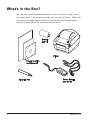
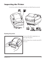
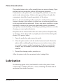
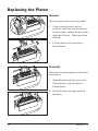
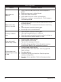
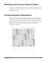
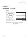
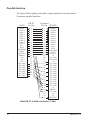
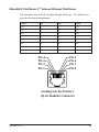
1
Zebra LP 2844
Desktop Printer
®
User Guide
Part #980483-001 | Rev. A
TM
ii
980483-001A
Proprietary Statement
This manual contains proprietary information of Zebra Technologies Corporation. It is intended solely for the information and use of parties operating and
maintaining the equipment described herein. Such proprietary information may not be used, reproduced, or disclosed to any other parties for any other purpose
without the expressed written permission of Zebra Technologies Corporation.
Product Improvements
Continuous improvement of products is a policy of Zebra Technologies Corporation. All specifications and signs are subject to change without notice.
FCC Compliance Statement
NOTE: This equipment has been tested and found to comply with the limits for a Class B digital device, pursuant to Part 15 of the FCC Rules. These limits are
designed to provide reasonable protection against harmful interference in a residential installation. This equipment generates, uses, and can radiate radio
frequency energy and, if not installed and used in accordance with the instructions, may cause harmful interference to radio communications. However, there is
no guarantee that the interference will not occur in a particular installation. If this equipment does cause harmful interference to radio or television reception,
which can be determined by turning the equipment off and on, the user is encouraged to try to correct the interference by one or more of the following measures:
■ Reorient or relocate the receiving antenna.
■ Increase the separation between the equipment and the receiver.
■ Connect the equipment into an outlet on a circuit different than that to which the receiver is connected.
■ Consult the dealer or an experienced Radio/TV technician for help.
NOTE: This unit was tested with shielded cables on the peripheral devices. Shielded cables must be used with the unit to insure compliance.
“The user is cautioned that any changes or modifications not expressly approved by Zebra Technologies Corporation could void the user’s authority to operate
the equipment.”
Liability Disclaimer
Zebra Technologies Corporation takes steps to assure that its published Engineering specifications and Manuals are correct; however, errors do occur. Zebra
Technologies Corporation reserves the right to correct any such errors and disclaims liability resulting therefrom.
No Liability for Consequential Damage
In no event shall Zebra Technologies Corporation or anyone else involved in the creation, production, or delivery of the accompanying product (including
hardware and software) be liable for any damages whatsoever (including, without limitation, damages for loss of business profits, business interruption, loss of
business information, or other pecuniary loss) arising out of the use of or the results of use of or inability to use such product, even ifZebra Technologies
Corporation has been advised of the possibility of such damages. Because some states do not allow the exclusion or limitation of liability for consequential or
incidental damages, the above limitation may not apply to you.
Trademarks
The Zebra logo and the zebra head design are both registered trademarks and LP 2844 is a service mark of ZIH Corp. Windows and MS-DOS are registered
trademarks of Microsoft Corp. All marks are trademarks or registered trademarks of their respective holders.
Copyrights
This copyrighted manual and the label printer described herein are owned by Zebra Technologies Corporation. All rights are reserved. Unauthorized
reproduction of this manual or the software in the label printer may result in imprisonment of up to one year and fines of up to $10,000 (17 U.S.C.506).
Copyright violators may be subject to civil liability.
©2004 ZIH Corp. All rights reserved.
980483-001A
iii
Shock Hazard
The printer and power supply should never be operated in a location where
either one can get wet. Personal injury could result.
Media
Always use high-quality, approved labels and tags. If adhesive backed
labels are used that DO NOT lay flat on the backing liner, the exposed
edges may stick to the label guides and rollers inside the printer, causing the
label to peel off from the liner and jam the printer. Approved supplies can
be ordered from your dealer.
If media run out while printing, DO NOT turn the power switch OFF (0)
while reloading or data loss may result. After loading new supplies, press
the feed button to resume printing.
Static Discharge
The discharge of electrostatic energy that accumulates on the surface of the
human body or other surfaces can damage or destroy the print head or
electronic components used in this device. DO NOT TOUCH the print
head or the electronic components under the top cover.
Thermal Printing
The print head becomes hot while printing. To protect from damaging the
print head and risk of personal injury, avoid touching the print head. Use
only the cleaning pen to perform maintenance.
iv
980483-001A
Contents
Introduction
Hello!. . . . . . . . . . . . . . . . . . . . . . . . . . . . . . . . . . . . . . . . . . . . . . . . . . . . .
What's in the Box?. . . . . . . . . . . . . . . . . . . . . . . . . . . . . . . . . . . . . . . . . . .
Inspecting the Printer. . . . . . . . . . . . . . . . . . . . . . . . . . . . . . . . . . . . . . . . .
Opening the printer . . . . . . . . . . . . . . . . . . . . . . . . . . . . . . . . . . . . . . .
Closing the printer. . . . . . . . . . . . . . . . . . . . . . . . . . . . . . . . . . . . . . . .
Reporting Damage . . . . . . . . . . . . . . . . . . . . . . . . . . . . . . . . . . . . . . .
Related Documentation . . . . . . . . . . . . . . . . . . . . . . . . . . . . . . . . . . . . . . .
1
2
3
3
5
6
6
Getting Started
Modes of Printing . . . . . . . . . . . . . . . . . . . . . . . . . . . . . . . . . . . . . . . . . . . 7
Attaching Power Supply . . . . . . . . . . . . . . . . . . . . . . . . . . . . . . . . . . . . . . 8
Loading Roll Media. . . . . . . . . . . . . . . . . . . . . . . . . . . . . . . . . . . . . . . . . . 9
Placing the Roll in the Media Compartment. . . . . . . . . . . . . . . . . . . . 9
Adjusting the Guides. . . . . . . . . . . . . . . . . . . . . . . . . . . . . . . . . . . . . 10
Operator Controls . . . . . . . . . . . . . . . . . . . . . . . . . . . . . . . . . . . . . . . . . . 11
Power Switch . . . . . . . . . . . . . . . . . . . . . . . . . . . . . . . . . . . . . . . . . . 11
Feed Button . . . . . . . . . . . . . . . . . . . . . . . . . . . . . . . . . . . . . . . . . . . 11
Status Light . . . . . . . . . . . . . . . . . . . . . . . . . . . . . . . . . . . . . . . . . . . . 11
Media Length Sensing . . . . . . . . . . . . . . . . . . . . . . . . . . . . . . . . . . . . . . . 12
Hooking Up the Printer and Computer . . . . . . . . . . . . . . . . . . . . . . . . . . 13
Interface Cable Requirements . . . . . . . . . . . . . . . . . . . . . . . . . . . . . . 13
USB Interface Requirements . . . . . . . . . . . . . . . . . . . . . . . . . . . . . . 14
Parallel Interface Requirements . . . . . . . . . . . . . . . . . . . . . . . . . . . . 14
Ethernet Interface Requirements. . . . . . . . . . . . . . . . . . . . . . . . . . . . 14
Serial Interface Requirements . . . . . . . . . . . . . . . . . . . . . . . . . . . . . . 14
Communicating with the Printer . . . . . . . . . . . . . . . . . . . . . . . . . . . . . . . 15
Universal Serial Bus (USB) Communications . . . . . . . . . . . . . . . . . 15
Parallel Communications . . . . . . . . . . . . . . . . . . . . . . . . . . . . . . . . . 15
Internal ZebraNet® PrintServer II™ Communications . . . . . . . . . . 15
Serial Communications . . . . . . . . . . . . . . . . . . . . . . . . . . . . . . . . . . . 16
Adjusting the Print Width . . . . . . . . . . . . . . . . . . . . . . . . . . . . . . . . . . . 17
Adjusting the Print Quality . . . . . . . . . . . . . . . . . . . . . . . . . . . . . . . . . . . 17
980483-001A
v
Operation & Options
Thermal Printing . . . . . . . . . . . . . . . . . . . . . . . . . . . . . . . . . . . . . . . . . . .
Replacing Supplies . . . . . . . . . . . . . . . . . . . . . . . . . . . . . . . . . . . . . . . . .
Printing in Peel-Mode . . . . . . . . . . . . . . . . . . . . . . . . . . . . . . . . . . . . . . .
Printing on Fan-Fold Media . . . . . . . . . . . . . . . . . . . . . . . . . . . . . . . . . .
Using the Cutter Option. . . . . . . . . . . . . . . . . . . . . . . . . . . . . . . . . . . . . .
19
20
21
22
23
Maintenance
Cleaning. . . . . . . . . . . . . . . . . . . . . . . . . . . . . . . . . . . . . . . . . . . . . . . . . .
Print Head Considerations . . . . . . . . . . . . . . . . . . . . . . . . . . . . . . . .
Media Path Considerations . . . . . . . . . . . . . . . . . . . . . . . . . . . . . . . .
Cleaning Card Considerations . . . . . . . . . . . . . . . . . . . . . . . . . . . . .
Platen Considerations . . . . . . . . . . . . . . . . . . . . . . . . . . . . . . . . . . . .
Lubrication . . . . . . . . . . . . . . . . . . . . . . . . . . . . . . . . . . . . . . . . . . . . . . .
Replacing the Platen . . . . . . . . . . . . . . . . . . . . . . . . . . . . . . . . . . . . . . . .
Replacing the Print Head. . . . . . . . . . . . . . . . . . . . . . . . . . . . . . . . . . . . .
Direct-Thermal LP Model. . . . . . . . . . . . . . . . . . . . . . . . . . . . . . . . .
25
26
26
26
27
27
28
29
30
Troubleshooting
Print Quality Problems . . . . . . . . . . . . . . . . . . . . . . . . . . . . . . . . . . . . . .
Manual Calibration . . . . . . . . . . . . . . . . . . . . . . . . . . . . . . . . . . . . . . . . .
Resetting the Factory Default Values . . . . . . . . . . . . . . . . . . . . . . . . . . .
Communications Diagnostics . . . . . . . . . . . . . . . . . . . . . . . . . . . . . . . . .
Feed Button Modes . . . . . . . . . . . . . . . . . . . . . . . . . . . . . . . . . . . . . . . . .
36
38
39
39
40
Appendix
Interfaces . . . . . . . . . . . . . . . . . . . . . . . . . . . . . . . . . . . . . . . . . . . . . . . . . 41
Universal Serial Bus (USB) Connector. . . . . . . . . . . . . . . . . . . . . . . 41
Parallel Interface . . . . . . . . . . . . . . . . . . . . . . . . . . . . . . . . . . . . . . . . 42
ZebraNet® PrintServer II™ Internal Ethernet PrintServer. . . . . . . . 43
Serial (RS-232) Connector . . . . . . . . . . . . . . . . . . . . . . . . . . . . . . . . 44
vi
980483-001A
980483-001A
vii
980483-001A
Introduction
This section describes what you get in your shipping box and provides an
overview of printer parts. This section also has procedures that describe
how to open and close the printer and report any problems.
Hello!
®
Thank you for choosing a Zebra LP 2844™ printer, a high-quality
on-demand printer manufactured by the industry leader in quality, service,
and value—Zebra Technologies Corporation. For over 25 years, Zebra
Technologies Corporation has provided customers with the highest caliber
of products and support.
Your printer is a high-quality, on-demand printer. The printer provides
direct-thermal printing.
This manual provides all of the information you will need to operate your
printer on a daily basis. To create label formats, refer to your programming
guide. This guide is available by contacting your distributor or dealer.
NOTE: Many printer settings may also be controlled by your printer’s
driver or label preparation software. Refer to the driver or
software documentation for more information.
Your printer, when connected to a host computer, functions as a complete
system for printing labels and tags.
980483-001A
1
What's in the Box?
Save the carton and all packing materials in case you need to ship or store
the printer later. After unpacking, make sure you have all parts. Follow the
procedures for inspecting the printer to familiarize yourself with printer
parts so you can follow the instructions in this book.
2
980483-001A
Inspecting the Printer
Look at the outside of the printer and make sure that all parts are present.
Opening the printer
To access the media compartment, you
must open the printer.
Pull the release levers towards you and lift
the cover.
980483-001A
3
INSPECTING THE PRINTER (continued)
After opening the printer, check the media compartment.
4
980483-001A
Closing the printer
Lower the top cover.
Press down until the cover snaps closed.
980483-001A
5
Reporting Damage
If you discover damage or missing parts:
■
Immediately notify and file a damage report with the shipping company.
The manufacturer is not responsible for any damage incurred during
shipment of the printer and will not cover the repair of this damage
under its warranty policy.
■
Keep the carton and all packing material for inspection.
■
Notify the authorized reseller
Related Documentation
Depending on the options you have ordered or choose to use with your new
printer, you will find the following documents helpful:
6
■
EPL2® Programmer's Manual—Programming for Page Mode Printing
■
Line Mode Programmer's Manual and the notice YOUR NEW PRINTER
and Its Printing Modes describing the line mode (EPL1) capability of
your printer's firmware.
■
ZebraNet® PrintServer II for Ethernet Networks Installation and
Operation Guide
■
Universal Serial Bus Specification available from the USB
Implementation Forum
TM
980483-001A
Getting Started
This section describes how to set up your printer for the first time and use
the most common operating procedures for loading media in tear-off mode.
Modes of Printing
You can operate this printer in different modes:
■
Standard tear-off mode allows you to tear off each label (or a strip of
labels) after it is printed.
■
In optional peel-off mode, the backing material is peeled away from the
label as it is printed. After this label is removed, the next one is printed.
■
In optional liner-free mode, labels have no backing. This option is only
available with a special platen.
■
In optional cutter mode, an attached unit cuts through the media.
The printer typically uses roll media, but you can use fan-fold or other
continuous media as well.
For procedures to use optional modes and features, refer to the Operation
and Options section.
980483-001A
7
Attaching Power Supply
Check the power supply to make certain it is appropriate for your input
voltage.
Warning: Use the power supply that came with your
printer.
Never operate the printer and power supply in an
area where they can get wet. Serious personal
injury could result!
1. Make sure the power switch is in the off position (down).
2. The DC power supply has a barrel connector on one end that must be
inserted into the power supply receptacle on the back of the printer.
3. Insert the separate AC power cord into the power supply.
4. Plug the other end of the cord into an appropriate AC electrical outlet.
Plug
Varies by
Country
AC
Power
Cord
Barrel
Connector
Power
Switch
Power
Supply
Power
Supply
Receptacle
8
980483-001A
Loading Roll Media
When you load media, you must place the roll on the media hangers and
then adjust the media guides.
You must use the correct media for the type of printing you require. You
must use direct thermal media.
Placing the Roll in the Media Compartment
Whether your roll media is inside or
outside wound you load it into the printer
the same way.
1. Open the printer. Remember that you
need to pull the release levers toward
the front of the printer.
2. Remove the outside length of media.
During shipment, the roll may become
dirty when handled or dusty when
stored. Removing the outside length
avoids dragging adhesive or dirty
media between the print head and
platen.
3. Separate and hold open the media
hangers.
4. Orient the media roll so that its
printing surface will be up as it passes
over the platen.
5. Lower the roll between the hangers
and close them onto the core.
980483-001A
9
Adjusting the Guides
The adjustable guides direct the media
toward the platen and print head.
1. Open the media guides by turning the
guide adjuster knob to the rear.
2. Thread the media through the guides.
3. Close the media guides by turning the
guide adjuster knob to the front. They
should just touch, but not restrict, the
edges of the media.
4. Close the top cover. Remember that
you need to release the cover lock,
lower the top cover, and press down
until the latches snap into place.
10
980483-001A
Operator Controls
Power Switch
Press up to turn ON or down to turn OFF the printer.
CAUTION: The power should be turned off before connecting or
disconnecting the communications and power cables.
Feed Button
Forces the printer to feed one blank label.
Takes the printer out of a “pause” condition. (The printer is put into
“pause” by either a programming command or an error condition.) See
“What the Status Light is Telling You” on page 33.
Use the Feed button for printer setup and status (see “Feed Button Modes”
on page 40).
Status Light
Functions as a printer operational indicator (see “What the Status Light is
Telling You” on page 33).
980483-001A
11
Media Length Sensing
Before you connect the printer to your computer, make sure that the printer
is in proper working order. You can do this by making the printer measure
media and print a status printout.
After loading media, perform the
following procedure that measures the
length of each label or tag. Make sure the
top cover of the printer is closed.
1. Make sure that printer power is off.
2. Press and hold the feed button.
3. Turn printer power on.
4. When the status light blinks, release
the feed button.
UKQ2933H U V4.28.19
Serial port : 96,N,8,1
Image buffer size:1032K
Fmem:000,0K,060.9K avl
Gmem:000K,0331K avl
Emem:000K,0331K avl
I8,0,001 rY JF WY
S2 D07 R024,000 ZT UN
q1200 Q1500,036
Option:
oRO
06 10 16
now in DUMP
5. The printer advances the media to
measure and verify the length of
individual labels or tags. The printer
then prints a status summary and
remains in diagnostic dump mode.
6. To begin normal operation, tap the
feed button. The printer prints "out of
DUMP" and advances a label.
If the status light remains amber or red or
you cannot get this printout, refer to
Troubleshooting on page 33.
out of DUMP
12
980483-001A
Hooking Up the Printer and Computer
Your printer will have one of two combinations of interfaces:
■
Universal Serial Bus (USB), parallel and serial
■
USB, ethernet, and serial
Each specific interface option—USB, parallel, ethernet, serial—is discussed
individually.
You must supply the required interface cable for your application.
CAUTIONS:Keep the power switch in the OFF position when
attaching the interface cable.
The power supply barrel connector must be inserted
into the power supply receptacle on the back of the
printer before connecting or disconnecting the communications cables.
This printer complies with FCC “Rules and Regulations,” Part 15, for Class B Equipment, using fully
shielded six-foot data cables. Use of longer cables or
unshielded cables may increase radiated emissions
above the Class B limits.
Interface Cable Requirements
Data cables must be of fully shielded construction and fitted with metal or
metalized connector shells. Shielded cables and connectors are required to
prevent radiation and reception of electrical noise.
To minimize electrical noise pickup in the cable:
Keep data cables as short as possible (6’ [1.83 m] recommended).
Do not tightly bundle the data cables with power cords.
Do not tie the data cables to power wire conduits.
980483-001A
13
USB Interface Requirements
Universal Serial Bus (version 1.1) provides a high-speed interface that is
compatible with your existing PC hardware. USB’s “plug and play” design
makes installation easy. Multiple printers can share a single USB port/hub.
Parallel Interface Requirements
The required cable (IEEE 1284-compliant is recommended) must have a
standard 36-pin parallel connector on one end, which is plugged into the
parallel port located on the back of the printer. The other end of the parallel
interface cable connects to the printer connector at the host computer.
For pinout information, refer to page 42.
Ethernet Interface Requirements
Ethernet provides a powerful networking capability that can be of use in a
variety of internet/intranet printing solutions. After you load media and
close the top cover, you can press the test button next to the connector on
the rear of the printer to get an ethernet configuration label.
Serial Interface Requirements
The required cable must have a nine-pin “D” type (DB-9P) male connector
on one end, which is plugged into the mating (DB-9S) serial port located on
the back of the printer. The other end of this signal interface cable connects
to a serial port at the host computer. Depending on the specific interface
requirements, this will most likely be a straight-through cable.
For pinout information, refer to page 44
14
980483-001A
Communicating with the Printer
Universal Serial Bus (USB) Communications
The printer is a terminal device when using a universal serial bus interface.
You can refer to the Universal Serial Bus Specification for details regarding
this interface.
Parallel Communications
When using the parallel port, typically there is no setup is required once the
cable is plugged in. If you should encounter any problems, consult the
user’s guide that came with your computer.
Internal ZebraNet® PrintServer II™ Communications
You can refer to the ZebraNet® PrintServer II™ for Ethernet Networks
Installation and Operation Guide for details regarding this interface.
980483-001A
15
Serial Communications
Serial communications between the printer and the host computer can be set
by the Y command.
Y Command
Use the serial port setup (Y) command to change the communications
settings on the printer.
1. With the host computer set at the same communications settings as the
printer, send the Y command to change the printer to the desired
settings.
2. Change the host computer settings to match the new printer settings.
Refer to the programming guide for more information about this command.
Default the Serial Parameters
The default communications parameters on the printer are 9600 baud, no
parity, 8 data bits, 1 stop bit. Many utilities, downloaders and programs use
these settings.
16
980483-001A
Adjusting the Print Width
Print width must be calibrated when you use a roll with a different width
from previous media.
Print width may be set by using the Set Label Width (Q) command
(described in the programming guide).
Adjusting the Print Quality
Print quality is influenced by the heat of the print head, the speed of the
media and the type of media you are using. Only by experimenting will
you find the optimal mix for your application.
If you find that the print darkness needs to be adjusted, refer to the heat
density (D) command (described in the programming guide).
If you find that the print speed needs to be adjusted, refer to the print speed
(S) command (described in the programming guide).
980483-001A
17
18
980483-001A
Operation & Options
This section helps you get the most from your printer.
You must use programming to control many of the printer’s functions. A
few examples:
■
The Q command (set form length) controls label length.
■
The O command (hardware options) has a parameter "D" that changes
the printing mode to direct thermal.
For detailed information about creating labels using page description
programming language, refer to the programming guide.
To improve print quality, changing both print speed and density may be
required to achieve the desired results. Your application’s printer driver
provides control of the speed and heat (density).
Thermal Printing
The print head becomes hot while printing. To protect from damaging the
print head and risk of personal injury, avoid touching the print head. Use
only the cleaning pen to perform maintenance.
The discharge of electrostatic energy that accumulates on the surface of the
human body or other surfaces can damage or destroy the print head or
electronic components used in this device. You must observe static-safe
procedures when working with the print head or the electronic components
under the top cover.
You must use the correct media for the type of printing you require. You
must use direct thermal media.
980483-001A
19
Replacing Supplies
If labels run out while printing, leave the printer power on while reloading
(data loss results if you turn off the printer). After you load a new label
roll, press the Feed button to restart.
Always use high quality, approved labels and tags. If adhesive backed
labels are used that don’t lay flat on the backing liner, the exposed edges
may stick to the label guides and rollers inside the printer, causing the label
to peel off from the liner and jam the printer. Approved supplies can be
ordered from your dealer.
20
980483-001A
Printing in Peel-Mode
ON
OFF
The optional dispenser allows you
to print in “peel-mode” where the
label backing follows a different path and
the labels are presented one at a time for
subsequent placement.
1. Remove several labels from the
backing material.
2. Open the top cover.
3. Open the dispenser door.
4. Switch on the label-taken sensor.
5. Insert the backing in front of the peel
bar and behind the peel roller.
6. Close the dispenser door.
7. Close the top cover.
8. Press the Feed button to advance the
label.
During the print job, the printer will peel
off the backing and present a single label.
Take the label from the printer so it will
print the next label.
980483-001A
21
Printing on Fan-Fold Media
Printing on fan-fold media requires you to
set both the media hangers and the media
guides in position.
Lock-down
Screw
1. Open the top cover.
2. With a sample of your media, adjust
the media hangers to the width of the
media. The hangers should just touch,
but not restrict, the edges of the
media.
3. Tighten the screw using a small
Phillips driver #1.
4. With a sample of your media, adjust
the guides to the width of the media.
The guides should just touch, but not
restrict, the edges of the media.
5. Insert the media through the slot at the
rear of the printer.
6. Run the media between the hangers
and guides.
7. Close the top cover.
22
980483-001A
Using the Cutter Option
Printers that have a bezel with a motorized blade can dispense one or more
forms that are then automatically cut from the media supply. This option
cuts through continuous paper from rolls and liner between labels. Keep
the cutter dry. Never use any solutions or solvents to clean the blade.
Use the f command to set the cut position and the C command to cut
immediately outside a form.
If the blade cuts through labels, adhesive
can jam the cutter.
1. Turn OFF (O) printer power and
unplug the power and interface cables
before clearing the cutter.
2. After removing debris, plug in the
power and interface cables, turn on
the printer, then test for normal
operation.
980483-001A
23
24
980483-001A
Maintenance
Cleaning
When you clean the printer, use one or more of the following supplies that
best suits your needs:
DESCRIPTION
Cleaning pens (12)
Cleaning swabs (25)
Cleaning cards, 4-in wide (25)
Save-a-Print Head film, 4-in wide (3)
The cleaning process takes just a couple of minutes using the steps outlined
below.
Printer Part
Method
Let the print head to cool for one minute, then use a new
cleaning pen to swab the print elements (the thin gray
line on the print head) from end to end. NOTE: You do
not have to turn off the printer to do this.
Print head
If print quality remains poor after cleaning, try the
Save-a-Print Head cleaning film to remove buildup
without damaging the print head. Call your authorized
reseller for more information.
Platen roller
Peel bar
980483-001A
Interval
As
necessary
or after
every five
rolls of
media
Manually rotate the platen roller. Clean it thoroughly
with 70% isopropyl alcohol and a cleaning swab,
cleaning card, or lint-free cloth.
Tear bar
Clean it thoroughly with 70% isopropyl alcohol and a
cotton swab.
Exterior
Water-dampened cloth
Interior
Brush or air blow
Cutter
Use tweezers to remove scraps
As needed
25
Adhesives and coatings of media can over time transfer onto the printer
components along the media path including the platen and print head.
This build-up can accumulate dust and debris. Failure to clean the print
head, media path and platen roller could result in inadvertent loss of labels,
label jams and possible damage to the printer.
Print Head Considerations
Always use a new cleaning pen on the print head (an old pen carries
contaminants from its previous uses that may damage the print head).
Media Path Considerations
Use a cleaning swab or pen to remove debris, dust or crust that has built-up
on the holders, guides and media path surfaces.
1. Use the alcohol in the cleaning swab or pen to soak the debris so that it
breaks up.
2. Wipe the area with the cleaning swab or pen to remove the debris.
3. Discard the cleaning swab or pen after use.
Cleaning Card Considerations
Use a cleaning card to remove debris that has built-up on the platen. Avoid
scrubbing or vigorously rubbing the platen; otherwise, the surface could be
damaged.
1. Open the printer and remove labels.
2. Place the cleaning card into the label path so that it is under the guides
and it extends between the print head and platen roller.
3. Close and latch the printer.
4. With the power switch on, press the feed switch to move the cleaning
card through the printer.
5. Discard the card after use.
26
980483-001A
Platen Considerations
The standard platen (drive roller) normally does not require cleaning. Paper
and liner dust can accumulate without effecting print operations.
Contaminates on the platen roller can damage the print head or cause the
media to slip when printing. Adhesive, dirt, general dust, oils and other
contaminates should be cleaned immediately off the platen.
However, the non-stick platen roller on linerless media printers requires
frequent cleaning to keep adhesive buildup from occurring and transferring
to the print head and the media path. Keep a new platen available as a spare
and install it whenever the printer has significantly poorer performance,
print quality or media handling. If sticking or jamming continues even after
cleaning, you must replace the platen.
The platen can be cleaned with a fiber-free swab (such as a Texpad swab)
or a lint free, clean, damp cloth very lightly moistened with medical grade
alcohol (70% pure or better).
1. Open the media door and remove the media.
2. Clean the platen surface with the alcohol moistened swab. Rotate the
platen while swabbing. Repeat this process two to three times with a
new swab to remove residual contaminates. Adhesives and oils, for
example, may be thinned by the initial cleaning but not completely
removed.
3. Discard the cleaning swab or pen after use.
Allow the printer to dry for one minute before loading labels.
Lubrication
No lubricating agents of any kind should be used on this printer! Some
commercially available lubricants, if used, will damage the finish and the
mechanical parts inside the printer.
980483-001A
27
Replacing the Platen
Removal
Open the printer and remove any media.
1. Using a pointed stylus (such as
tweezers, small slot-head screwdriver,
or razor-knife), unhook the tabs on the
right and left sides. Then rotate them
forward.
2. Lift the platen out of the printer’s
bottom frame.
Assembly
Make sure the right bearing is on the shaft
of the platen.
1. Align the platen with the gear to the
left and lower it into the printer’s
bottom frame.
2. Rotate the tabs back and snap them
into place.
28
980483-001A
Replacing the Print Head
In the event you need to replace the print head, read the procedure and
review the removal and installation steps before actually replacing the print
head.
Prepare your work area by protecting against static discharge. Your work
area must be static-safe and include a properly grounded conductive
cushioned mat to hold the printer and a conductive wrist strap for yourself.
NOTE: Turn the printer power off and unplug the power cord before
replacing the print head.
980483-001A
29
Direct-Thermal LP Model
Before following the steps in this procedure, open the printer by pulling the
release latches forward then lifting the top cover.
Removal
1. Use a #1 Phillips driver to loosen the
four screws that hold the latch frame
to the top case.
2. Grasp the print head spring and pull it
to the left; then, slide it free of the
latch frame.
3. Gently pull the wire bundles from the
print head.
4. Use a #1 Phillips driver to loosen the
two screws and washers and release
the print head from the latch frame
and bracket.
30
980483-001A
Replacing the LP Print Head (Continued)
Assembly
1. Route the print head cables under the
latch shaft and plug the print head
cables into the receptacles on the print
head.
2. Hold the print head against the bracket
while replacing the screws and
washers; attach the ground wire using
the right screw and washer. Use a #1
Phillips driver to tighten the screws.
3. Slip the left end of the print head
spring into the left side of the latch
bracket; then slide the right end into
the other side. The angle of the “V”
fits into the indent on the top of the
print head bracket.
4. Align the latch bracket up to the top
case and ensure that the cable are not
bent or pinched.
5. Replace the four screws that hold the
latch bracket to the top case and use a
#1 Phillips driver to tighten them.
6. Clean the print head with the cleaning
pen.
Reload media. Plug in the power cord,
turn on the printer and print a status report
to ensure proper function.
980483-001A
31
32
980483-001A
Troubleshooting
What the Status Light is Telling You
Color
None
Green
Amber
Status
off
constant
constant
Solution or Reason
1.
Check power connection from the A.C. outlet to power
supply to printer.
1.
2.
3.
Printer printing (normal operation).
Printer paused; ready to receive data (normal operation).
Printer paused; waiting for user action (for example, to
take a dispensed label or to tap the feed button).
1.
The cover open sensor is active. Press top cover to close
and lock.
Printer has a syntax or command error. Check program
and resend print job.
2.
1.
blinking
Red
1.
constant
980483-001A
2.
2.
3.
Firm download in progress. Indicator lights red, then
green.
Signal to begin media length sensing after turning ON
printer. Release the feed button.
Media is out. Reload a new supply. Press feed button to
continue.
Power-up failure. Switch power OFF then back ON.
Printer ready to receive flash programming during
firmware download.
33
Printer Operation
Problem
Solution or Reason
1.
Media does not
advance.
2.
3.
4.
5.
1.
Media moves but
nothing is printed.
Printing is faded or
poor.
Prints only partial
label or skips a label.
Printing stops and
indicator lights Amber
or Red.
3.
4.
Verify that the labels are the correct type (thermal transfer
or direct thermal).
Check that the roll is loaded with the thermal side facing
up.
Clean the print head with cleaning pen.
Ensure top cover is locked closed.
1.
2.
3.
4.
Clean the print head with cleaning pen.
Adjust print speed/darkness in software.
Check the media and verify that print surface is facing up.
Check that correct thermal media is in use.
1.
2.
3.
4.
Perform media length sensing.
Label caught on print head.
Top cover is not properly latched.
Possible software problem. Check the printer memory
configuration. Refer to the programming manual.
1.
2.
Perform media length sensing.
Possible problem with label stock. Use only approved
labels and tags.
Possible label jam.
Insufficient memory for label size. Check the printer
memory configuration.
Possible software problem. Refer to the programming
manual.
2.
3.
4.
5.
34
Check interface cable connections from computer to
printer.
Make sure top cover is locked closed.
Check that labels are correct.
Verify media has print surface up for printing.
Printer has a syntax or command error. Check program
and resent print job.
980483-001A
Media Handling
Problem
Solution or Reason
Label Dispenser
1.
2.
Printing continues
between labels.
Prints one label and
then stops.
3.
1.
Make sure label-taken sensor is on.
The label-taken sensor is blocked or dirty. Remove any
scraps or dust.
Continuous media may be set. Verify form length setting
through programming Q command. See the programming
guide.
Verify the quantity has been correctly set.
Cutter Operation
Blade cuts through
labels instead of
cutting liner between
labels.
Media jammed in
cutter.
Blade fails to cut
direct thermal paper
or label liner.
980483-001A
1.
Verify form length setting through programming
1.
Unplug power and interface cables. Use tweezers to
remove scaps from cutter opening.
1.
Use programming C command to cycle cutter several times
without media to perform a self-cleaning. See the
programming guide.
Cutter must be replaced.
2.
35
Print Quality Problems
No print on the label.
■
You must use the correct media for the method of printing you require.
You must use direct thermal media.
■
Is the media loaded correctly? Follow the instructions in “Loading the
Media” on page 9.
The printed image does not look right.
■
The print head is dirty. Clean the print head according to the
instructions on page 31.
■
The print head is under temperature.
■
Adjust the print darkness and/or print speed. Use the S and D commands
in the programming guide.
■
The media being used is incompatible with the printer. Be sure to use
the recommended media for your application, and always use
manufacturer-approved labels and tags.
There are long tracks of missing print (blank vertical lines) on
several labels.
■
The print head is dirty. Clean the print head according to the
instructions on page 31.
■
The print head elements are damaged. Replace the print head (see
“Replacing the Print Head” on page 32).
The print head is under temperature.
■
36
Continue printing while the print head reaches the correct operating
temperature.
980483-001A
The printing does not start at the top of the label, or misprinting of
one to three labels.
■
The media may not be threaded under the media guides. Refer to
“Loading the Media” on page 9.
■
The printer needs to be calibrated. Refer to “Auto Calibration” on page
11.
A label format was sent to, but not recognized by, the printer.
■
Is the printer in pause mode? If so, press the feed button.
■
If the status LED is on or flashing, refer to “What the Status LED is
Telling You” on page 33.
■
Make sure the data cable is correctly installed.
■
A communications problem has occurred. First, make sure that the
correct communications port on the computer is selected. Refer to
“Communicating with the Printer” on page 15.
Print out is only programming codes, unexpected characters, or has
no printing at all.
■
Print a status report to check if line mode is active.
■
With programming, use the <LF>OEPL1<LF> command switch to line
mode. Use the <ESC>EPL2 command to switch to page mode.
■
To manually switch between modes, perform these steps:
Turn printer power off.
Hold the feed button while turning printer power on.
When the light starts flashing, release the feed button.
When the light starts flashing again, press and hold the feed button.
When the light turns steady amber, release the feed button.
When the light turns steady green, the mode is changed.
Verify the mode by printing and inspecting a status report.
980483-001A
37
Manual Calibration
Manual calibration is recommended whenever you are using pre-printed
media or if the printer will not correctly auto calibrate.
1. Make sure the printer power is off and that media is loaded.
2. Press and hold the feed button then turn on the printer power.
3. Continue to hold the feed button until the status light LED flashes.
Release the feed button.
4. The printer will set the media sensor for the label backing being used.
After the printer is done making this adjustment, the roll will
automatically feed until a label is positioned at the print head.
5. The configuration settings (similar to the example below) will print.
Upon completion, the printer will save the new settings in memory and
remain in diagnostic dump mode.
6. Press the feed button. The printer will dispense another label with the
message "Out of DUMP" and be ready for normal operation.
UKQ2933H U V4.28.19
Serial port : 96,N,8,1
Image buffer size:1032K
Fmem:000,0K,060.9K avl
Gmem:000K,0331K avl
Emem:000K,0331K avl
I8,0,001 rY JF WY
S2 D07 R024,000 ZT UN
q1200 Q1500,036
Option:
oRO
06 10 16
now in DUMP
out of DUMP
38
980483-001A
Resetting the Factory Default Values
Sometimes, resetting the printer to the factory defaults solves some of the
problems. For troublehooting and to overwrite all stored parameters, send
the ^default command.
Communications Diagnostics
If there is a problem transferring data between the computer and printer, try
putting the printer in the communications diagnostics mode. The printer
will print the ASCII characters and their respective hexadecimal values (a
sample is shown below) for any data received from the host computer. To
find out how, refer to the power off mode procedure in “Manual
Calibration” on page 38.
980483-001A
39
Feed Button Modes
Printer Condition
Feed Button Action
Printer is OFF
Printer is off.
Tapping or holding the button has no result.
Printer is ON
Cover is open
Labels, tags or
fan-fold forms are
loaded.
Continuous media roll
is loaded.
Fresh media has just
been loaded.
40
Tapping or holding the button has no result.
Tap the button once to perform a "form feed."
Hold the button to perform a "continuous feed."
The printer stops at the top of the next form.
Tap the button to perform a "line feed."
The printer stops on the next line.
Hold the button to perform a "continuous feed."
The printer stops at the next line when you release the button.
Tap the button to advance media. If printer fails to detect media,
the platen stops turning and the status LED lights Red; if the
printer cannot detect a gap within 11 inches (27.9 cm), the platen
stops turning and the status LED lights Amber.
980483-001A
Appendix
Interfaces
Universal Serial Bus (USB) Connector
The figure below displays the cable wiring required to use the printer’s
USB interface.
2
3
1
4
Pin
Signal
1
Vbus - N/C
2
D-
3
D+
4
Ground
Shell
Shield/
Drain Wire
For information on the USB interface, go to the USB web site at:
Http://www.usb.org
980483-001A
41
Parallel Interface
The figure below displays the cable wiring required to use the printer's
Centronics parallel interface.
HOST
DB-25
Pin No.
STROBE~
DATA 0
DATA 1
DATA 2
DATA 3
DATA 4
DATA 5
DATA 6
DATA 7
ACK~
BUSY
PAPER ERR.
SELECT
AUTOFD~
ERROR~
N/A
N/A
N/A
SIG. GND
SIG. GND
SIG. GND
SIG. GND
SIG. GND
SIG. GND
SIG. GND
1
2
3
4
5
6
7
8
9
10
11
12
13
14
15
16
17
18
19
20
21
22
23
24
25
Centronics
Pin No. PRINTER
1
2
3
4
5
6
7
8
9
10
11
12
13
14
15
16
17
18
19
20
21
22
23
24
25
26
27
28
29
30
31
32
33
34
35
36
STROBE~
DATA 0
DATA 1
DATA 2
DATA 3
DATA 4
DATA 5
DATA 6
DATA 7
ACK~
BUSY
PAPER ERR.
SELECT
AUTOFD~
n/c
SIG. GND
CHAS GND
+5V
SIG. GND
SIG. GND
SIG. GND
SIG. GND
SIG. GND
SIG. GND
SIG. GND
SIG. GND
SIG. GND
SIG. GND
SIG. GND
SIG. GND
n/c
ERROR~
SIG. GND
n/c
n/c
SELECTIN~
Male DB-25 to Male Centronics (Cable)
42
980483-001A
ZebraNet® PrintServer II™ Internal Ethernet PrintServer
This interface uses an RJ-45 straight-through cable type. The table below
provides the pinout assignments.
Signal
Pin
Pin
Signal
Tx+
1
1
Tx+
Tx-
2
2
Tx-
Rx+
3
3
Rx+
---
4
4
---
---
5
5
---
Rx-
6
6
Rx-
---
7
7
---
---
8
8
---
Pin 4
Pin 3
Pin 2
Pin 1
Pin 5
Pin 6
Pin 7
Pin 8
Looking into the Printer’s
RJ-45 Modular Connector
980483-001A
43
Serial (RS-232) Connector
The printer operates as a Data Communication Equipment (DCE) and
normally connects via a standard RS-232 modem cable to a Data Terminal
Equipment (DTE) such as a computer or terminal with a default
configuration of 9600 baud, 8 bit data, 1 stop bit and No parity.
Host
N/C
RxD
TxD
DTR
GND
DSR
RTS
CTS
RI
DB-9
Pin #
1
2
3
4
5
6
7
8
9
DB-9
Pin #
1
2
3
4
5
6
7
8
9
Printer
+5 Volts*
TxD
RxD
CTS
GND
RDY
N/C
RDY
N/C
Female DB-9 to Male DB-9
Host
N/C
RxD
TxD
DTR
GND
DSR
RTS
CTS
RI
DB-25
Pin #
8
3
2
20
7
6
4
5
22
DB-9
Pin #
1
2
3
4
5
6
7
8
9
Printer
+5 Volts*
TxD
RxD
N/C
GND
RDY
N/C
RDY
N/C
Female DB-25 to Male DB-9
*+5 volts at 150 mA for external device (e.g. KDU or scanner)
44
980483-001A