1
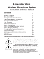
Liberator One
Wireless Microphone System
Instruction and User Manual
Contents:
Introduction
System Features
The Transmitter
Microphone Connector Lock
Transmitter Battery Information
Microphone Information
The Receiver
Antenna Installation
Audio Connections
Using the Liberator One System
Using Multiple Systems
Changing the System Frequency
Troubleshooting
FCC License Application Instructions
Warranty
Specifications
2
3
4
5
6
8
10
11
16
17
19
21
24
25
27
28
Explanation of Graphical Symbols in the Operating Instructions:
The lightning flash with arrowhead symbol, within an
equilatral triangle, is inteneded to alert the user to the
presence of uninsulated "dangerous voltage" within the
product's enclosure that may be of sufficient magnitude to
constitute a risk of electric shock to persons.
The exclamation point within an equilateral triangle is
intended to alert the user to the presence of important
operating and mainteneance (servicing) instructions in the
literature accompanying the appliance.
CAUTION! TO REDUCE THE RISK OF ELECTRIC
SHOCK, DO NOT REMOVE COVER. NO USERSERVICABLE PARTS INSIDE. REFER SERVICING TO
QUALIFIED SERVICE PERSONNEL.
1
Installation Note:
READ THIS BOOK!
The Liberator One System has been designed for easy installation by
persons with minimal electronic experience, although some technical
knowledge will be helpful. Ultimate system performance depends on
proper antenna placement and installation, so pay close attention to the
antenna placement guidelines. Take a few minutes to completely read
the instructions. Doing so will save you installation time and insure
optimum system performance.
FCC License Requirement:
Your Liberator One Wireless Microphone requires an FCC License for
lawful operation. To apply for an FCC License, fill out the enclosed
license form and mail it to the FCC address shown on the form.
Instructions for filling out the form can be found on page 24. The FCC
charges an $80.00 License Fee.
Introduction:
The Liberator One Wireless Microphone System is a highperformance, yet economical cordless microphone. It allows the wearer
complete freedom of movement, with a range of 300' or more.
Advanced Williams Wireless technology allows easy installation, reliable
operation, and excellent sound quality.
How it Works:
The talker wears the Lavalier Microphone and the Transmitter Belt Pack.
The Transmitter converts sounds picked up by the microphone into FM
radio signals, using the microphone cord as a broadcast antenna.
The Liberator One Receiver picks up the broadcast and converts the
FM radio signals into an electrical signal, which is normally fed into the
sound system amplifier. The wireless microphone performs the same
function as a wired microphone, but uses an FM radio signal traveling
between the microphone and sound system instead of a wire. When the
system is functioning properly, the performance of the wireless
microphone should be virtually identical to the performance of the same
microphone if it were connected to the sound system with a wire.
2
IMPORTANT SYSTEM FEATURES:
The Liberator One Wireless Microphone System has several
innovative features that make it unique from conventional wireless
microphones.
Frequency Selectable System
Both the Transmitter and Receiver are digitally frequency-synthesized
for precise frequency control and to allow the system operating
frequency to be easily changed. This feature eliminates inconvenience
and down-time when the frequency must be changed to avoid
interference from other radio services. Unlike other wireless
microphones, your Liberator One does not have to be returned to the
factory for new crystals and re-tuning if an alternate frequency is
needed. Your installer can change the frequency on the spot!
Operates on the Professional High-Band Frequencies
Your Liberator One operates on the VHF (Very High Frequency) HighBand, between 169 to 172 MHz. Unlike the crowded low-band
frequencies used by most inexpensive systems, the high-band has a low
probability of interference from other radio services.
Helical Filters
Helical filters are highly selective filters that prevent out-of-band signals
from CB's, cordless phones, and other radio services from interfering
with the Liberator One .
Compander Noise Reduction System
The Liberator One features advanced noise reduction circuitry to
assure ultra-quiet operation and maximum dynamic range.
Sophisticated Squelch Circuitry:
The Liberator One Receiver is designed to automatically squelch or
mute when the Transmitter is out of range, when the system audio
becomes excessively noisy at extreme range, or if a nearby signal is
interfering with reception. Unlike other systems that only use the
Transmitter radio signal strength to control muting, the Liberator One
looks at radio signal strength and noise present in the audio to control
the mute function. This makes the mute function smoothly and
predictably and helps prevent outside radio signals from interfering with
your system.
3
TRANSMITTER CONTROLS AND FEATURES
The WMS T11 Transmitter is compact and easy to operate. The
microphone plugs into the MIC jack. If a rechargeable 9V battery is
used, the charger also plugs into the MIC jack to charge the battery.
Transmitter Control Switch
The Transmitter has a single control switch on top of the unit. There are
3 positions - OFF, MUTE, and ON.
OFF - Turns the FM carrier and microphone off. For storage and
charging if the rechargeable battery is used.
MUTE - Turns the FM carrier signal on, but the microphone is off. For
stand-by and muting. The transmitter is on to "capture" the receiver, but
the mic is off.
ON - Turns the FM carrier signal on and the microphone on. For normal
operation.
Switching from ON to MUTE or from MUTE to ON will not cause a "pop"
in the sound system, allowing silent operation of the microphone.
Switching from ON to OFF or from MUTE to OFF will cause a slight
"pop." Having the operator turn down the sound system control for the
wireless microphone before shutting the Transmitter off will prevent this.
T11 Transmitter Controls and Jack
4
Microphone Connector Lock
The Connector Lock can be added to the microphone plug to prevent the
microphone plug from accidentally coming out during use. The
connector locking pin attaches to the mic plug and fits into the oval hole
next to the MIC jack when the back cover of the transmitter is opened.
To attach the Connector Lock, unscrew the plug shell and slip on the
locking clip as shown. Then tighten down the plug shell.
To Insert or Remove the Mic Plug:
1. Open the back of the Transmitter case. First open the battery
compartment flap. Then open the back of the case like a book, as
shown.
2. Insert or withdraw the mic plug and locking pin as shown. Be sure to
push the plug all the way in.
3. Close the back cover and battery compartment to lock the mic plug in.
Inserting and Removing the Connector Lock
5
TRANSMITTER BATTERY INFORMATION
Battery Installation:
To install the battery, lift up on the battery compartment tab. Handle the
battery wires gently when attaching the battery to the snaps. Lay the
battery inside the compartment, tuck in the excess wire, and snap the
battery compartment shut.
Alkaline Batteries:
The Transmitter is supplied with a 9V alkaline battery (Eveready 522).
An alkaline battery will power the Transmitter for 5 - 6 hours of
continuous use, or 10 - 12 hours with intermittent use.
Lithium Batteries:
Lithium 9V batteries, such as the Kodak Ultralife, may also be used
when longer continuous battery life is needed. The Lithium batteries will
provide 20 -22 hours of continuous use.
Rechargeable Batteries:
CAUTION: DO NOT attempt to recharge non-rechargeable batteries!
The battery may rupture, causing injury or equipment damage.
There are two types of rechargeable batteries for the T8 Transmitter:
BAT 003 (VARTA TR 7/8):
The BAT 003 is a standard 9V package that fits in the Transmitter
battery compartment. It will provide about 2.5 hours of use per charge.
The BAT 003 can be charged with the BAT 005 or BAT 004 Charger.
Recharging requires 12-14 hours.
BAT SYS A (High-Capacity Battery Pack):
The BAT SYS A includes an external battery pack (BAT 018), heavyduty charger (BAT 019), and a special belt clip case (CCS 015) to hold
the battery pack and the Transmitter. It is intended for use in situations
that require extended operating time from a rechargeable battery. The
BAT 018 battery pack will provide about10 hours of use per charge.
Recharging requires 12-14 hours.
NOTE: The BAT 005 and BAT 004 Chargers CANNOT be used with the
BAT 018 Battery Pack. Use only the BAT 019 Charger with the
BAT 018 Extended Capacity Battery Pack.
6
Battery Charging:
There are two Chargers available for the BAT 003 Rechargeable Battery.
The BAT 005 Charger plugs directly into the Transmitter MIC jack to
charge the battery without removing it from the Transmitter. The
BAT 004 Charger has battery snaps, allowing the battery to be snapped
onto the Charger. NOTE: DO NOT USE SUBSTITUTE CHARGERS.
Other Chargers will not provide a full charge with the BAT 003 Battery.
BAT 005 Charger with Plug
BAT 004 Charger with Snaps
To charge the battery with the BAT 005 Charger, plug the Charger cord
into the Transmitter MIC jack and plug the charger into a wall outlet.
Make sure the Transmitter is turned OFF while charging. When the unit
is charging, a red indicator light will glow on top of the Transmitter.
Charge the battery for 14 - 16 hours.
To charge the battery with the BAT 004 Charger, remove the battery
from the Transmitter and attach it to the Charger snaps. Plug the
Charger into a wall outlet and charge for 14 - 16 hours.
If you are using the BAT SYS A Extended-Capacity Battery System,
refer to the charging instructions included with the battery system.
Rechargeable Battery Care:
Ni-Cad batteries can be recharged hundreds of times if they are properly
cared for. Batteries should be charged at least once a month, even if
they are not in use. Try to let the battery drain completely before
recharging, then immediately charge it for 14 - 16 hours.
Avoid repeated short-term (1 hour or less) use followed by charging. If
battery life becomes very short (15 - 30 min.), leave the Transmitter
turned on until the battery is completely discharged and immediately
recharge the battery. DO NOT leave the Charger plugged in once the
battery is fully charged (about 14 hours).
7
Microphones
The Liberator One System is available with two standard microphone
choices. The WMS L100 System includes the MIC 041 Omnidirectional
Condenser . The WMS L150 System includes the high performance
MIC 839 (Shure 839) Omnidirectional Condenser.
MIC 041
MIC 839
MIC 022
MIC 015
Optional microphones include the MIC 022 Cardioid Condenser and the
MIC 015 Noise-Cancelling Headset microphone.
MIC 839 (SHURE) WIRING
+
MIC -
Red
Black
3.5mm
Mini Phone
Plug
28" Cord
Shield
8
Alternate Microphones:
The WMS T11 Transmitter is compatible with any lavalier microphone
that can be wired as a two-wire element. If you are using an alternate
microphone, follow the wiring diagrams below. See the microphone
data sheets for wiring details. Williams Sound cannot guarantee the
performance of microphones we do not supply.
Important Technical Note:
The microphone cord is used as the transmitting antenna. The cord
length tunes the antenna. The mic cord should be cut to 28 inches. To
prevent RF feedback, electret microphones should have a small .001 uF
capacitor directly across the mic element, inside the mic housing. The
mic connector is a 3.5 mm mini phone plug.
3.5mm
Mini Phone
Plug
+
MIC -
28" Cord
.001
Wiring Diagram, Two-Wire Electret Microphones
Electret Mics:
The T11 Transmitter is designed to supply power to electret
microphones. Positive voltage is supplied to the tip of the microphone
plug.
+
+
MIC 28" Cord
10 uF
Tantalum
3.5mm
Mini Phone
Plug
Wiring Diagram, Dynamic Microphones
Dynamic Mics:
If a dynamic microphone is used, a 10 uF blocking capacitor must be
added as shown in the drawing.
9
Receiver Controls and Features
Liberator One
WMS R11, Front Panel:
(A) Power Switch - turns
Receiver on and off.
Professional VHF Wireless Mic Receiver
Programmable Digital Tuning
Advanced Noise Reduction
Power
RF
AF
Williams
Sound
(B) Power ON Indicator - glows
when Receiver is on.
(C) RF Indicator - glows when
radio carrier is present.
A
B
C
D
(D) AF Indicator - flashes when
audio signal is present.
WMS R11, Rear Panel:
(A) Balanced Mic Output male XLR jack for use with
balanced Mic inputs on mixers
and amplifiers. Signal is on
pins 2 and 3, common is on
pin 1. Source impedance is
200 Ohms. Output is
0 - 160 mVrms. Any Load
impedance may be used.
VHF Wireless Microphone Receiver
Model WMS R11
Williams Sound Corp.
Minneapolis, Minnesota, U.S.A.
Power
120 VAC
50/60 hz
3W
Balanced
Mic Output
A
Unbalanced Output Level
Line Output
B
C
Antenna
75 Ohm
D
E
(B) Unbalanced Line Output - 1/4" phone jack for use with unbalanced
Aux or Line inputs on mixers and amplifiers. The Line Output can also
accomodate balanced line-level inputs using a stereo 1/4" plug. The
signal is connected to the plug tip. The plug ring and sleeve are
connected to common. Source impedance is 100 Ohms. Output is
0 - 2 Vrms. Load impedance should be greater than 1000 Ohms.
(C) Output Level Control - provides adjustment of the Mic Output and
Line Output levels.
(D) Antenna Connector - 75 Ohm F-type connector for the system
antenna.
(E) Power Connector - the AC power cord plugs into the power
connector.
10
Receiver Antenna Installation
There are two antenna types, depending on which Liberator One
system you purchased. The WMS L100 System includes the ANT 011
Whip Antenna. The WMS L150 System includes the ANT 016 WallMount Dipole Antenna. The ANT 011 Whip Antenna is suitable for
portable and general use. The ANT 016 Dipole is suitable for rackmount installations or when extended range is necessary. The ANT 016
is more efficient than the Whip Antenna and will provide the greatest
system range.
Using the Whip Antenna:
The ANT 011 Whip Antenna attaches directly to the Antenna Connector
on the back of the WMS R11 Receiver. Carefully thread the fitting on
and tighten by hand while holding the whip upright. Do not use a pliers
or wrench to tighten the connector.
When using the whip antenna, make sure the Receiver and antenna are
within line-of-sight of the Transmitter. Try to keep the Receiver and
antenna as close to the Transmitter as practical. Do not put the
Receiver and antenna
inside a metal cabinet.
Do not place the
Receiver where metal
objects will be between
the antenna and the
transmitter. Some metal
objects such as steel
beams, reinforcing bars,
metal studs, ductwork
and foil-backed
insulation may not be
visible, but they can
Attach Antenna Rod
cause reception
to Right-Angle Connector
problems. Materials
such as wood, glass,
and masonry are
generally transparent to
radio signals. If you
cannot get acceptable
Attach Right-Angle
reception with the whip
Connector to Receiver
antenna, use the ANT
Antenna Connector
016 Dipole Antenna in a
more optimal location.
Whip Antenna - ANT 011
11
Dipole Antenna Assembly:
Assemble the Dipole Antenna as shown below.
ANT 016
Dipole Antenna
Assembly, Side View
Attach Antenna Rod 1
2
4
Attach Right-Angle
Connector
1
3
12
Attach Antenna Rod 2
Attach to
mounting surface
with screws
Dipole Antenna (ANT 016) Installation
The WMS L150 Liberator One System includes the ANT 016 Dipole
Antenna. Assemble the antenna as shown on the previous page. Use
the Coaxial Feedline Cable included to connect the Dipole Antenna to
the Antenna Connector on the rear panel of the WMS R11 Receiver.
The Dipole Antenna is designed to be mounted on a wall. Be sure to
use proper fasteners (wall anchors, screws). For proper performance,
the Coaxial Feedline Cable MUST exit the antenna at a right angle, as
shown, for at least 12" before bending the cable.
ANT 016
Dipole Antenna
Cable Routing,
Front View
Cable Clamps - 12" apart
Coax should exit
antenna at right
angle as shown
13
Antenna Location:
ANTENNA LOCATION IS THE MOST CRITICAL PART OF THE
INSTALLATION!
DO:
- Choose an antenna location that maintains line-of-sight between the
antenna and transmitter, as close to the area where the Transmitter will
be used as is practical.
- Try to mount the antenna at least six to ten feet above floor level, in a
vertical orientation.
- Position the antenna in a horizontal orientation if it will be mounted
directly above the area where the Transmitter will be used.
- Choose an antenna location that allows a short (less than 100')
feedline cable run. It is better to run a long, balanced audio cable rather
than a long antenna feedline cable.
- Try different antenna locations if you cannot achieve satisfactory
operation.
DO NOT:
- Mount the antenna on a steel beam or behind a wall that could shield
the antenna. Metal plaster lath, metal studs, foil-backed insulation,
metal ducts, and metal reinforcing bars in concrete walls can all act to
shield radio signals. Wood, glass, fabric, and masonry are generally
transparent to radio signals. People can also block radio signals.
- Mount the antenna at the rear of an auditorium if the Transmitter will
generally be used in the front.
- Position the antenna in a vertical orientation directly above the area
where the transmitter will be used; the antenna is essentially "dead" off
both ends.
- Coil up excess antenna feedline cable. This can act as an inductor and
de-tune the antenna. Cut the cable to length and install a new "F"
connector.
The Antenna Feedline Cable:
The Coaxial Feedline Cable may be extended up to 100 feet if
necessary, with a slight loss in system range. Fifty-foot extension cables
are available from Williams Sound (Part Number WCA 008 50). If you
supply your own extension cable, use RG59 coax with at least 90%
shielding and "F"-type connectors. Do not splice coax cable.
14
Antenna System:
This receiver is intended for connection to an antenna system, possibly
including outdoor antennas, installed to provide some protection against
voltage surges and built-up static charges. Articles 810 and 820 of the
National Electric Code, ANSI/NFPA 70 -1984, provide information with
respect to grounding of the mast and supporting structure, the lead-in
wire to an antenna discharge unit, and the coaxial cable system; and
with respect to the size of grounding conductors, location of antennadischarge units, connection to grounding electrodes, and the
requirements for the grounding electrode. If an outside antenna is
connected to the antenna terminal of the receiver, be sure the antenna
system is grounded in a manner similar to the accompanying figure.
Antenna Grounding
15
Audio Connections:
The WMS R11 Receiver can be connected to a microphone input or a
line-level input on your mixer or amplifier.
(1) Line-Level Connections:
Use an appropriate audio cable to connect the WMS R11 Receiver
"Unbalanced Line Output" 1/4" jack to an AUX IN, TAPE IN, or LINE IN
jack on your amplifier or mixer. This connection will result in the lowest
system noise level and leave you an extra Mic Input jack on your mixer
or amplifier. Be sure to use high-quality, shielded cables and avoid
unbalanced cable runs of six feet or longer. Use the "Output Level"
Control on the rear panel of the Receiver to balance the wireless mic
level with your other microphones and to achieve a convenient control
setting on your mixer.
(2) Microphone-Level Connections:
Use a standard microphone cable to connect the WMS R11 Receiver
"Balanced Mic Output" XLR jack to a MIC IN jack on your mixer or
amplifier. If you do not have a microphone cable, you can purchase one
ready-made from an electronics parts store, or you can make one as
shown. Always use shielded cable and XLR connectors.
R11
Receiver
Amplifier or Mixer
MIC INPUTS
LINE INPUTS
VHF Wireless Microphone Receiver
Model WMS R11
Williams Sound Corp.
Minneapolis, Minnesota, U.S.A.
Tape In
Aux In
Power
120 VAC
50/60 hz
3W
MIC 1
MIC 2
MIC 3
Balanced
Mic Output
Unbalanced Output Level
Line Output
2
1
XLR
1/4"
Mic-Level
Line-Level
Male XLR
2
1
3
16
Antenna
75 Ohm
2-Wire, Shielded
Cable
Female XLR
2
1
3
Using the Liberator One System:
(1) Install the battery in the Transmitter and plug in the MIcrophone as
shown on page 5.
(2) Make sure the sound system is turned OFF. Place the Liberator
One WMS R11 Receiver near the sound system amplifier or mixer.
Plug the AC line cord into the Receiver, and the Receiver into an AC
outlet. If the Receiver is to be rack-mounted, use the RPK 003 Rack
Mount Kit (not included) and the ANT 016 Wall-Mount Dipole Antenna.
(3) Connect the WMS R11 Receiver "Mic Output" or Line Output" to your
amplifier or mixer as shown on page 16.
(4) Install the ANT 011 Whip Antenna or the ANT 016 Wall Mount Dipole
Antenna as shown on page 11.
(5) Turn the WMS R11 Receiver on by pressing the power switch. The
"Power" indicator should glow. Turn the sound system on and turn the
control down for the input connected to the wireless mic.
(6) Clip the microphone to your collar or lapel. Place the Transmitter in a
pants pocket or clip it to a belt or waistband using the Belt Clip Case
provided. Do not coil or bunch up the microphone cord.
(7) Turn the Transmitter switch to the "ON" position. The "RF" indicator
light on the front panel of theWMS R11 Receiver should glow to indicate
a radio carrier signal is present.
(8) Talk into the microphone. You should see the "AF" indicator flashing
on the front of the WMS R11 Receiver, indicating the audio signal is
present.
(9) Slowly turn up the mixer control on your sound system while talking
into the microphone, until you hear your voice coming through the sound
system. Adjust the "Output Level" control on the rear panel of the WMS
R11 Receiver to achieve a useful setting on the mixer control. If the
system feedback (howling) occurs, reduce the mic level on the mixer
control. Using the optional Cardioid Microphone (MIC 022) can help
eliminate feedback too.
(10) Walk around the room, checking for range and "drop-outs", or dead
spots. Try different antenna locations to provide the best coverage. It
may not be possible to completely eliminate all dead spots, but careful
antenna placement should eliminate most of them.
17
Mute Switch Operation:
If you are wearing the wireless microphone and do not wish to be heard,
move the Transmitter contol switch to the "MUTE" (center) position. This
will leave the Transmitter on, but will silence the microphone. This
feature is especially useful for visits to the restroom, etc. The Mute
Switch is designed for silent muting of the microphone during normal
operation. Moving the control from ON to OFF or from MUTE to OFF
may create a "pop" noise in the sound system. Turning down the
wireless mic input control on the mixer before shutting the Transmitter
OFF will prevent this.
System Range:
System range (operating distance) is highly dependent on the location
and building in which the wireless mic system is used. Under most
circumstances, system range should be 300 feet or more between the
Transmitter and Receiver Antenna. Some locations will allow greater
range, some may allow less. The system is designed to go quiet, or
"squelch" when its operating range is exceeded.
Audio Quality:
The "sound" of a wireless microphone depends on the characteristic
sound of the microphone used with it. The lavalier microphones offered
by Williams Sound are capable of professional quality sound
reproduction. More sophisticated (and expensive) sound systems can
include equalizers to achieve better performance from lavalier
microphones. Your dealer can provide help with equalization.
Battery Management:
The best insurance for trouble-free operation is to install a fresh alkaline
battery before each use of the system. Rechargeable batteries provide
economical operation, but they offer relatively short life per charge and
must be charged in a very specific way to maintain their operating life.
Refer to the battery instructions on page 6.
Radio Interference:
The Liberator One Wireless Mic System is designed to minimize the
possiblity of interference from other radio services, but interference can
occur. Interference may be a buzzing sound, voice transmissions,
"beeps" or just a blanking of the desired signal. If this occurs, your
dealer can generally solve the problem by changing the operating
frequency of the system. The Liberator One System does not have to
be returned to the factory for a frequency change. Frequency-changing
instructions can be found on page 21.
18
Using Multiple Transmitters:
It is possible to use more than one Transmitter with one Receiver,
provided that only one Transmitter is turned on at a time. If two or more
Transmitters are turned on at the same time on the same frequency,
they will block each other and none will produce a clear sound. If
multiple microphones are to be used, it is best to use multiple complete
systems, each operating on a separate frequency.
Using Multiple Systems:
It is possible to operate up to 10 Liberator One Systems in the same
place at the same time if each is set to a different (non-adjacent)
operating frequency. DO NOT operate more than one system on the
same frequency, or they will interfere with each other. Refer to the
frequency-change instructions on page 21 to set each system on a
different frequency.
The frequencies listed on page 21 and inside the cover of the Receiver
may be used together. For applications requiring more than six sytems
used simultaneously, consult your dealer for frequency cooordination.
Rack Panel Kit:
A Rack Panel Mounting Kit (RPK 003) allows one or two Liberator One
WMS R11 Receivers to be mounted in a 3-1/2" x 19" rack panel.
RPK 003 Rack Panel Mounting Kit
19
Antenna Splitters:
To simplify remote antenna installation in multiple system applications,
we offer a 1:2 Antenna Splitter Kit (ANT 009) and a 1:4 Antenna Splitter
Kit (ANT 010), which allow more than one WMS R11 Receiver to share
an antenna. These are not necessary if the ANT 011 Whip Antennas
are used. Refer to the diagrams below for wiring details.
It may be necessary to use additional antenna line amplifiers or
amplified splitters if passive splitter loss results in unacceptable
operating range. If a line amplifier is used, it should be installed
between the antenna and the splitter. A 75 Ohm, TV-type amplifier
providing 10 - 20 dB of gain can be used. Amplifiers that contain an FM
Broadcast Band trap are preferred to prevent overloading by out-of-band
Receiver 1
Antenna
Receiver 2
Antenna
Antenna
CSA 002
2:1
Splitter
Two Receivers Sharing One Antenna
Receiver 1
Antenna
Receiver 3
Antenna
Receiver 2
Antenna
Antenna
CSA 004
4:1
Splitter
Receiver 4
Antenna
Four Receivers Sharing One Antenna
20
radio signals such as FM radio stations.
UP
1 2 3 4 5 6 7 8
DOWN
Switches set for 169.445 MHz
1
2
3
4
5
6
7
8
Changing the
System
Frequency:
The Liberator One WMS
T11 Transmitter and WMS
R11 Receiver use
21
digital frequency synthesizer circuitry to allow easy frequency (channel)
selection. Changing the system frequency is simple, if you follow the
directions and heed the precautions below.
Precautions:
To avoid interference, never operate more than one wireless microphone
on the same frequency at the same time. Up to 4 Liberator One
systems can be operated simultaneously, but each must be on a
different frequency.
Your Liberator One system is pre-set to 169.445 MHz. Try using this
channel first. If you encounter interference or need a separate
frequency for multiple systems, then select another frequency from the
chart. If local interference cannot be overcome, refer to the additional
frequency selections in the back of this manual.
The WMS T11 Transmitter and WMS R11 Receiver MUST be set to the
same frequency to work together. Always change them as a pair.
WMS T11 Transmitter Frequency Selection:
Open the Transmitter back cover as shown. Compare the position of the
black switches on the circuit board to the diagram to determine the
Transmitter frequency setting. The programming diagram is repeated
on a label inside the WMS R11 Receiver cover. See the following page
for switch settings.
Changing the Transmitter Frequency:
(1) Make sure the Transmitter is turned off. Locate the frequencyprogramming switches as shown.
(2) Move the switches to the positions indicated for the frequency you
have selected. Use a straightened paper clip or pen point (not a pencil
point) to move the switches up or down.
22
(3) Close the Transmitter cover and change the Receiver frequency to
match the
Transmitter
frequency.
GeneralUse
WMS R11 PCB
Top View
ON
1 2 3 4
5 6
OFF
1 2 3 4
ON
Front
Frequency
Programming
Switch
ON
S3
OFF
1 2 3 4
5 6
S2
5 6
UP
OFF
DOWN
WMS R11 Receiver Parts Layout
Frequency
(MHZ)
S2 Settings
1 2 3
4
S3 Settings
2 3 4 5
5
6
1
15 = 169.445
31 = 170.245
47 = 171.045
63 = 171.845
DN
DN
DN
DN
DN
DN
DN
DN
DN
DN
DN
DN
DN
DN
UP
UP
UP
DN
UP
DN
UP
UP
UP
UP
DN
DN
UP
UP
DN
DN
UP
UP
DN DN UP
DN DN UP
UP UP DN
UP UP DN
DN
DN
DN
DN
6
16 = 169.505
32 = 170.305
48 = 171.105
64 = 171.905
UP
UP
UP
UP
UP
UP
UP
UP
UP
UP
UP
UP
UP
UP
DN
DN
DN
UP
UP
DN
UP
DN
UP
UP
DN
DN
UP
UP
DN
DN
UP
UP
DN DN UP
DN DN UP
UP UP DN
UP UP DN
DN
DN
DN
DN
Frequencies:
The following frequencies are allocated under FCC Part 90 for general
use:
Transmitter Frequency Programming Chart:
CHANNEL FREQUENCY
NO.
(MHz)
1
2
SWITCH SETTINGS
3
4
5
6
7
8
15
169.445
DN DN DN DN UP UP UP UP
31
170.245
DN UP DN DN UP UP DN DN
47
171.045
DN UP DN DN UP UP DN UP
63
171.845
DN UP UP DN UP UP DN
23
DN
16
169.505
UP DN UP UP
DN DN DN UP
32
170.305
UP DN DN DN
DN UP DN UP
48
171.105
DN UP DN UP UP DN DN UP
64
171.905
DN UP UP UP UP DN DN DN
If you need to change the system channel to avoid interference or to
operate multiple systems, DO NOT use the following frequencies
together: 15&16, 31&32, 47&48, 63&64. Any other combination of
these eight can be used together.
Special-Use Frequencies:
Additional frequencies are available for restricted use under FCC Rules,
Part 74. Ask your Authorized Dealer for details.
WMS R11 Receiver Frequency Selection:
NOTE: THE RECEIVER MUST BE SET TO THE SAME FREQUENCY
AS THE TRANSMITTER.
24
Changing the WMS R11 Receiver Frequency:
(1) Make sure the Receiver is unplugged from AC power.
(2) Use a 5/64" hex screwdriver to loosen the four screws on the side of
the Receiver case. Lift off the top cover.
(3) Locate the two frequency-programming switches, S2 and S3, as
shown on the diagram above. Select the Receiver frequency to match
the Transmitter frequency by setting the programming switches as
shown in the Receiver programming table.
(4) Replace the cover on the Receiver and tighten the four side screws.
(5) Plug the Receiver into AC power and turn it on. Turn the Transmitter
on and make sure the" RF" indicator lights on the Receiver.
Troubleshooting:
NOTE: "Lightning Bolt" marking on the receiver chassis signifies
CAUTION! To reduce the risk of electrical shock, do not remove the
cover. No user serviceable parts inside. Refer servicing to quailified
service personnel.
The most common problems are due to the following conditions:
(1) A dead battery in the Transmitter. Always start with a fresh battery
when the Transmitter is used. If you are having trouble with a
rechargeable battery, try using a new alkaline battery.
(2) Broken cords and connectors. This will result in a "scratchy" noise or
"pops" when cords and connectors are moved back and forth. These
components take the most abuse in the system and are most likely to
fail. They will last a reasonable length of time if they are well cared for,
but they will not last indefinitely. Microphone cords and connectors are
repairable.
(3) BOX 1: Enter the system frequency from STEP 1, above, on the first
line of BOX 1.
BOX 2: Enter "MO" on the first line of BOX 2.
BOX 3: Enter the number of Transmitters you will be using on the
top line.
BOX 4: Enter "15F3".
BOX 5: Enter ".025".
BOX 6 - 11: Skip
BOX 12: Enter the number of Transmitters you will be using on the
"Portable" line inside BOX 12.
Poor antenna placement. Improper antenna placement can result
25
in
BOX 13: Enter ".2" on the first line. (Area of operation ... is .2 miles
radius of station A.) Fill in the next two lines with the
latitude and longitude of your location in degrees and
minutes. Fill in 00" for seconds. A local library can supply
this information. For example:
Degrees
Minutes
Seconds
Direction
Latitude
42
27
00
N
Longitude
98
15
00
W
BOX 14: Enter the street address of your facility on line A.
BOX 15: Enter your city on line A.
BOX 16: Enter your county on line A.
BOX 17: Enter the two-letter abbreviation for your state on line A.
BOX 18: Enter the street address, city, state, and telephone number
where a person responsible for system operation may be
reached. You must fill this in, even if it is the same
information as above.
BOX 19: Skip
BOX 20: Enter "IB".
BOX 21: Enter the legal name of the person, business, or
organization applying for the license.
BOX 22: Enter the mailing address to which the license and any
further correspondence should be mailed. Fill it in
completely, even if it is the same as the address above.
BOX 23: Enter the city name for the license mailing address.
BOX 24: Enter the two-letter state abbreviation.
BOX 25: Enter the ZIP Code for the license mailing address.
BOX 26: Enter an "X" in the "NO" Box on the first line.
BOX 27: Enter 28, 29: Skip.
BOX 28: Enter an "X" in the box that best describes your
organization.
BOX 31: Enter "90.75A" in the small box marked "Give Rule
Section" inside of BOX 31. Also enter a short, clear
statement that includes a general explanation of your
business or activity and how the Transmitter will be used.
BOX 32: Enter an "X" in the "New Station" box.
BOX 33: Enter an "X" in the "Yes" box.
BOX 34: Enter an "X" in the "No" box.
BOX 35, 36: Skip.
BOX 37: Enter the name and phone number of the person
completing this form. Fill this in completely, even if you
are duplicating information.
poor system range and excessive "dead spots." See the instructions on
page 14. If the system mutes and the RF indicator light goes out, it
26
generally means the RF signal is too weak (out of range or bad battery)
or there is an interfering signal present.
(4) Frequency mis-match between the Transmitter and Receiver. Make
sure both are on the same frequency. See page 21-23.
(5) Using two Transmitters on the same frequency at the same time.
Transmitters used simultaneously must be on different frequencies. See
page 21.
(6) Radio interference. If you experience interference from another radio
service, refer to the frequency change instructions on page 21-23.
(7) Failure to read and follow the instructions.
FCC License Requirement:
The Liberator One, like all high-band wireless microphone systems,
requires an FCC license for legal operation. We have enclosed a
license form for your convenience. Complete the form, following the
instructions below, and mail it to the FCC at the address listed on the
form. When the application is approved, the FCC will mail the license to
you.
Important Note: Be sure to fill in all items completely, even if you
are duplicating information. Do not use phrases like "see above." The
FCC will reject incomplete applications.
Instructions for FCC License Application,
Form 574:
STEP 1:
Determine your Transmitter operating frequency. Your Liberator One
was shipped to you pre-set on Frequency 15 = 169.445 MHz. If you
have not changed the system frequency, write 169.445 MHz on the line
below.
If you have changed the system frequency, open the RECEIVER and
look at the frequency-programming label. Compare the position of
the eight programming switches inside the Transmitter to the
27
positions shown on the label and read the corresponding frequency.
Write that frequency on the line below.
Carrier Frequency:
System Range:
Signal/Noise Ratio:
Frequency Response:
Total Harmonic Distortion:
Field-selectable, 169 -172 MHz
Varies with application, 300 feet nom.
90 dB, NAB Weighted
40 Hz to 18 kHz, +1, -2dB
1% Maximum
TRANSMITTER FREQUENCY:______________________________
Dimensions:
Weight:
Color:
Case Material:
3-5/8" x 2-3/8" x 7/8"
4 ounces with battery
Black
Shatter-proof polyallomer
Battery Type:
Battery Drain:
Battery Life:
9 Volt alkaline, Lithium, or VARTA TR 7/8 Ni-Cad
40 mA
Eveready 522: 5 - 6 hours
Kodak Ultralife: 9 - 10 hours
VARTA TR 7/8: 2.5 hours/charge
Battery charges through the MIC jack
Red LED lights while charging
Charging Jack:
Charging Indicator:
RF Carrier Frequency:
RF Output Power:
Frequency Control:
Frequency Stability:
Modulation:
Antenna:
FCC Approval:
Pre-Emphasis:
Modulation Control:
Mic Input Level:
Microphone Connector:
Microphone Power:
Microphone Type:
Optional Microphones:
Control Switch:
28 STEP 2:
Field-selectable by jumpers on PCB,
169 - 172 MHz
40 mW, nominal
Digital Frequency Synthesizer, PLL
+ .005%, crystal reference
FM, + 15 kHz
Integral with MIC cord
Part 90.217, Part 74, FCC ID: CNM75ST11
75 uS
2:1 Linear Compressor
90 mV maximum
3.5 mm Mini Phone Jack
Supplies positive DC for condenser mics on
tip of mic plug
Condenser, MIC 041 or MIC 839, omni,
28" cord, 3.5mm mono phone plug
MIC 022 - Cardioid Condenser,
MIC 015 - Noise-Cancelling Headset
3-Way, off / mic-mute / mic-on
(1) Tear off the front sheet of the license application Form 574, labeled
Dimensions:
Weight:
Color:
6-1/2" W x 2-1/2" H x 6" D
2 pounds
Black
Power Requirements:
120 VAC, 50 or 60 Hz, 3W
DC: 12V (Factory mod required)
Internal, 5mm, 1/16A, standard blow
Fuse:
Operating Frequency:
Frequency Control:
Frequency Stability:
Modulation:
IF:
Sensitivity:
Squelch:
De-Emphasis:
Audio Output:
Field-selectable by switches on PCB,
169 - 172 MHz
Digital Frequency Synthesizer, PLL
+ .005%, crystal reference
FM, + 15 kHz
10.7 MHz
.9 uV at 12 dB Sinad, 12.1 dBf
Automatic, noise-determined, 70dB min S/N ratio
75 uS
Audio Control:
Balanced Mic-Level, XLR
0 - 160 mVrms, 200 Ohm source Z, any load Z
Unbalanced Line-Level, 1/4" phone jack
0 - 2 Vrms, 100 Ohm source Z,
min. 1 kOhm load Z
Screwdriver adjust pot
Indicators:
LED, "RF" carrier, "AF" audio modulation, power
Antenna:
Wall Mount, 1/2-wave dipole or 1/4-wave whip,
75 Ohm, "f"-type connector, RG59 Coax
Rack Mount Kit:
RPK 003 Rack Panel Kit mounts one or two
R11's in two IEC rack spaces
"WORKSHEET."
(2) Using a pencil, fill in the WORKSHEET as follows:
29