1
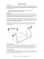
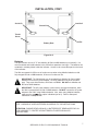
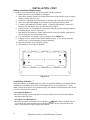
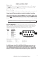
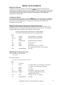
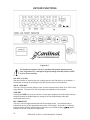
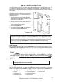
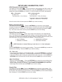
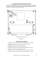
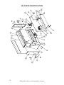
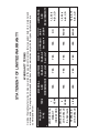
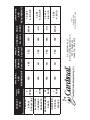
204 WEIGHT INDICATOR INSTALLATION and TECHNICAL MANUAL 8555-M313-01 Rev G 06/12 PO BOX 151 WEBB CITY, MO 64870 PH (417) 673-4631 - FAX (417) 673-5001 www.cardinalscale.com Technical Support: Ph:Rev 866-254-8261 x [email protected] 8555-M313-O1 G x 204 Installation & Technical Printed in USA 2 8555-M313-O1 Rev G x 204 Installation & Technical TABLE OF CONTENTS Specifications x x x x x x x x x x x x x x x x x x x x x x x x x x x x x x x x x x x x x x x x European Declaration of Conformity x x x x x x x x x x x x x x x x x x x x x x x x Site Preparation Requirements x x x x x x x x x x x x x x x x x x x x x x x x x x x x Installation x x x x x x x x x x x x x x x x x x x x x x x x x x x x x x x x x x x x x x x x x x x Unpacking x x x x x x x x x x x x x x x x x x x x x x x x x x x x x x x x x x x x x x x x x Mounting x x x x x x x x x x x x x x x x x x x x x x x x x x x x x x x x x x x x x x x x x x Interconnectionsx x x x x x x x x x x x x x x x x x x x x x x x x x x x x x x x x x x x x AC Power Adapter x x x x x x x x x x x x x x x x x x x x x x x x x x x x x x x x x x x Batteries x x x x x x x x x x x x x x x x x x x x x x x x x x x x x x x x x x x x x x x x x x Battery Installation/Replacementx x x x x x x x x x x x x x x x x x x x x x x Low Battery Indicator x x x x x x x x x x x x x x x x x x x x x x x x x x x x x x x Battery Status x x x x x x x x x x x x x x x x x x x x x x x x x x x x x x x x x x x x Battery Charging x x x x x x x x x x x x x x x x x x x x x x x x x x x x x x x x x x Load Cell Connection x x x x x x x x x x x x x x x x x x x x x x x x x x x x x x x x Load Cell Connections with Over 30 Feet of Cable x x x x x x x x x x x Main PCB and Jumpers (Figure No. 5) x x x x x x x x x x x x x x x x x x x x Serial Interface Specifications x x x x x x x x x x x x x x x x x x x x x x x x x x x x Serial Data Formats x x x x x x x x x x x x x x x x x x x x x x x x x x x x x x x x x x x x Keypad Functions x x x x x x x x x x x x x x x x x x x x x x x x x x x x x x x x x x x x x Annunciators x x x x x x x x x x x x x x x x x x x x x x x x x x x x x x x x x x x x x x x x x Setup and Calibration x x x x x x x x x x x x x x x x x x x x x x x x x x x x x x x x x x Setup Review x x x x x x x x x x x x x x x x x x x x x x x x x x x x x x x x x x x x x x x x Calibration Seal Installation x x x x x x x x x x x x x x x x x x x x x x x x x x x x x x Care and Cleaning x x x x x x x x x x x x x x x x x x x x x x x x x x x x x x x x x x x x x Error and Status Displays x x x x x x x x x x x x x x x x x x x x x x x x x x x x x x x Before You Call Service x x x x x x x x x x x x x x x x x x x x x x x x x x x x x x x x x 204 Parts Identification x x x x x x x x x x x x x x x x x x x x x x x x x x x x x x x x x Page 1 Page 2 Page 3 Page 4 Page 4 Page 4 Page 4 Page 4 Page 5 Page 6 Page 6 Page 7 Page 7 Page 7 Page 7 Page 8 Page 8 Page 9 Page 10 Page 11 Page 13 Page 18 Page 19 Page 19 Page 20 Page 20 Page 22 SERIAL NUMBER _____________________ DATE OF PURCHASE _________________ PURCHASED FROM __________________ ____________________________________ ____________________________________ ____________________________________ RETAIN THIS INFORMATION FOR FUTURE USE PRECAUTIONS Before using this indicator, read this manual and pay special attention to all "WARNING" symbols: IMPORTANT ELECTRICAL WARNING STATIC SENSITVE 8555-M313-O1 Rev G x 204 Installation & Technical I FCC COMPLIANCE STATEMENT WARNING! This equipment generates uses and can radiate radio frequency and if not installed and used in accordance with the instruction manual, may cause interference to radio communications. It has been tested and found to comply with the limits for a Class A computing device pursuant to Subpart J of Part 15 of FCC rules, which are designed to provide reasonable protection against such interference when operated in a commercial environment. Operation of this equipment in a residential area may cause interference in which case the user will be responsible to take whatever measures necessary to correct the interference. You may find the booklet “How to Identify and Resolve Radio TV Interference Problems” prepared by the Federal Communications Commission helpful. It is available from the U.S. Government Printing Office, Washington, D.C. 20402. Request stock No. 001-000-00315-4. PROPER DISPOSAL When this device reaches the end of its useful life, it must be properly disposed of. It must not be disposed of as unsorted municipal waste. Within the European Union, this device should be returned to the distributor from where it was purchased for proper disposal. This is in accordance with EU Directive 2002/96/EC. Within North America, the device should be disposed of in accordance with the local laws regarding the disposal of waste electrical and electronic equipment. It is everyone’s responsibility to help maintain the environment and to reduce the effects of hazardous substances contained in electrical and electronic equipment on human health. Please do your part by making certain that this device is properly disposed of. The symbol shown below indicates that this device must not be disposed of in unsorted municipal waste programs. All rights reserved. Reproduction or use, without expressed written permission, of editorial or pictorial content, in any manner, is prohibited. No patent liability is assumed with respect to the use of the information contained herein. While every precaution has been taken in the preparation of this manual, the Seller assumes no responsibility for errors or omissions. Neither is any liability assumed for damages resulting from use of the information contained herein. All instructions and diagrams have been checked for accuracy and ease of application; however, success and safety in working with tools depend to a great extent upon the individual accuracy, skill and caution. For this reason the Seller is not able to guarantee the result of any procedure contained herein. Nor can they assume responsibility for any damage to property or injury to persons occasioned from the procedures. Persons engaging the procedures do so entirely at their own risk. 2II 8555-M313-O1 Rev G x 204 Installation & Technical SPECIFICATIONS Power Requirements: 115 VAC 50/60Hz 12 VDC 300mA wall plug-in UL/CSA listed AC power adapter, Cardinal part number 728R90. Also available, for 230 VAC operation, Cardinal part number 6800-1045 OR (6) C cell batteries, Alkaline, Ni-Cad or NiMH (batteries not included) Operating Temperature: 14 to 104 ºF (-10 to +40 ºC) Display: Six digit, seven segment, 1" high LCD Sensitivity: 1.2uV/division (0 to 3.0 mV/V), Class III Signal Input Range: 0.2mV to 15mV max. Transducer Excitation: 5.0 VDC Number of Load Cells: up to 4 each 350: Load Cell Cable Length: 30 feet max. Resolution: 5,000 divisions Capacities: 1,000 to 5,000 divisions commercial up to 10,000 divisions noncommercial Division Value: 1, 2, 5 or 10 x 1, 0.1, 0.01, 0.001 Sample Rate: 1 to 10 samples per second selectable Auto Zero Range: 0.5 or 1 through 9 divisions Weighing Units: Pounds, kilograms, ounces or grams Keyboard: Membrane type with 7 keys Enclosure Size: 8" W x 6 5/8" H x 2 1/8" D (204 x 168 x 54mm) Enclosure Construction: 304 Stainless Steel Weight: 2.1 lb (without batteries) – 3.1 lb (with batteries) Certifications This equipment is certified to comply with the requirements for a Class III/IIIL device by the x National Conference on Weights and Measurements (Certificate No. 02-016A1) x Measurement Canada (Approval No. AM-5436) x Australian Government National Standards Commission (Approval No. S430) x And for accuracy Class III and IIII by OIML (Certificate No. R76/1992-DK-02.03) 8555-M313-O1 Rev G x 204 Installation & Technical 3 EUROPEAN DECLARATION OF CONFORMITY Manufacturer: Cardinal Scale Manufacturing Company PO Box 151 203 East Daugherty Webb City, Missouri 64870 USA Telephone No. 417 673 4631 Fax No. 417 673 5001 Product: Non-automatic Weight Indicating Instrument Model Numbers 204, 204S Serial Number EXXXYY-ZZZ where XXX = day of year YY = last two digits of year ZZZ = sequential number The undersigned hereby declares, on behalf of Cardinal Scale Manufacturing Company of Webb City, Missouri, that the above-referenced product, to which this declaration relates, is in conformity with the provisions of: Council Directive 2006/95/EC Low Voltage Directive European Standard EN50082: 1995 for radiated emissions and European Standard EN50082-2: 1995 Class B for EMC immunity. The Technical Construction File required by this Directive is maintained at the corporate headquarters of Cardinal Scale Manufacturing Company, 203 East Daugherty, Webb City, Missouri. ____________________ Mark Levels Quality Assurance Administrator 4 8555-M313-O1 Rev G x 204 Installation & Technical SITE PREPARATION REQUIREMENTS The Model 204 Weight Indicator is a precision weight indicating instrument. As with any precision instrument, it requires an acceptable environment to operate at its peak performance and reliability. This section is provided to assist you in obtaining such an environment. Environmental The Model 204 Weight Indicator meets or exceeds all certification requirements within a temperature range of 14 to 104 °F (-10 to +40 °C). In order to keep cooling requirements to a minimum, the indicator should be placed out of direct sunlight and to provide adequate air circulation, keep the area around the indicator clear. Do not place the indicator directly in front of a heating or cooling vent. Such a location will subject the indicator to sudden temperature changes, which may result in unstable weight readings. Insure that the indicator has good, clean AC power and is properly grounded. In areas subject to lightning strikes, additional protection to minimize lightning damage, such as surge suppressors, should be installed. Electrical Power The 204 indicator has been designed to operate from 115 VAC @ 50/60Hz using a 115 VAC to 12 VDC 300 mA wall plug-in UL/CSA listed AC power adapter. NOTE! For 230 VAC operation, an optional AC power adapter is required, Cardinal part number 6800-1045. The socket-outlet supplying power to the indicator should be on a separate circuit from the distribution panel and dedicated to the exclusive use of the indicator. The socket-outlet shall be installed near the equipment and shall be easily accessible. The wiring should conform to national and local electrical codes and ordinances and should be approved by the local inspector to assure compliance. On installations requiring 230 VAC power, it is the responsibility of the customer to have a qualified electrician install the proper power adapter plug that conforms to national electrical codes and local codes and ordinances. 8555-M313-O1 Rev G x 204 Installation & Technical 5 INSTALLATION Unpacking Carefully remove indicator from shipping carton and inspect it for any damage that may have taken place during shipment. Keep carton and packing material for return shipment if it should become necessary. The purchaser is responsible for filing all claims for any damages or loss incurred during transit. Should your indicator come already installed on a scale, the following installation information does not apply to you. Mounting The Model 204 Weight Indicator may come mounted on a column or it may be mounted on a desktop or other smooth, flat, horizontal surface or it may be mounted on a wall using two (2) #10 screws placed 6.00 inches apart on the wall. Refer to Figure No. 1 for illustrations of the mounting bracket. This bracket may be removed or left in place for desktop use. Regardless of how and where you mount indicator, it should be in a safe area where it will not be in the way of normal traffic. The location chosen should be free of temperature extremes and water, is not subject to direct sunlight and should be mounted where the display is easily viewed and within easy reach of the operator. If wall mounted, make certain the structure and mounting bolts are of sufficient strength to support the indicator. The mounting bracket should be securely fastened to the wall so it cannot break loose. 6.00 Inches Figure No. 1 Interconnections All Input, Output and power connections to the 204 are made at the rear panel of the indicator. Connections for the Load Cell input and the RS-232 Serial I/0 are all made via 9 pin "D" shaped subminiature connectors. The optional 12VDC wall plug-in UL/CSA listed AC adapter is connected using a power jack. Refer to Figure No. 2 for the layout of the rear panel. AC Power Adapter To power the 204 using the 12VDC wall plug-in AC power adapter, connect the plug from the adapter into the power jack on the back of the indicator and then plug the power adapter into the proper electrical outlet. Refer to Figure No. 2. 6 8555-M313-O1 Rev G x 204 Installation & Technical INSTALLATION, CONT. Serial I/O Load Cell Ground Lug Thumb Screw 12 VDC Battery Door Figure No. 2 Batteries The 204 indicator can use 6 "C" size Alkaline, Ni-Cad or NiMH batteries (not included). You must first obtain and install batteries in the 204 before operations can begin. The batteries are contained in a battery holder inside the indicator. Access is via a removable panel on the back of the indicator. The 204 can operate for 200 hours of continuous use when using Alkaline batteries or with fully charged Ni-Cad or NiMH batteries, 50 hours of continuous use. IMPORTANT! The 204 indicator can be operated from Alkaline, Ni-Cad or NiMH batteries or from an AC power adapter. All six (6) batteries must be of the same type. They must all be Alkaline, all Ni-Cad or all NiMH. DO NOT mix Alkaline and Ni-Cad or NiMH batteries. IMPORTANT! The AC power adapter is also used to recharge the batteries, when the 204 is operated from Ni-Cad or NiMH batteries. DO NOT connect the AC power adapter to the 204 if using Alkaline batteries. Also, when using Alkaline batteries, make sure the niCAd setup option is disabled (set to 0). Refer to Setup and Calibration or Setup Review. CAUTION: RISK OF EXPLOSION IF BATTERY IS REPLACED BY AN INCORRECT TYPE. DISPOSE OF USED BATTERIES ACCORDING TO THE INSTRUCTIONS. ATTENTION: RISQUE D'EXPLOSION SI LA BATTERIES EST REMPLACE'E PAR UN TYPE INCORRECT. REJETEZ LES BATTERIES UTILISE'ES SELON LES INSTRUCTIONS. 8555-M313-O1 Rev G x 204 Installation & Technical 7 INSTALLATION, CONT. Battery Installation/Replacement To install or remove the batteries, the following steps should be followed: 1. Make sure the AC power adapter is unplugged. 2. Remove the indicator from the mounting bracket and turn the indicator over so that the display is facing away from you. 3. Locate the rectangular panel on the back of indicator and remove the thumb screw. 4. Remove the panel (lift straight up and slide it out) exposing the battery holder. 5. If installing new batteries, proceed to step 6. If replacing the batteries, remove all 6 batteries from the battery holder and then proceed to step 6. 6. Install the new 6 "C" size batteries in the holder, noting the polarity markings located in the battery holder. Refer to Figure No. 3. 7. After placing all 6 batteries in holder, replace panel on back of indicator (slide tab into slot on rear panel) and install thumb screw. 8. Turn the indicator over (display facing up) and press the ON|OFF key. 9. If display turns on, batteries have been installed correctly. If not, remove panel and check for one or more improperly positioned batteries. 10. Return the indicator to the mounting bracket. 11. The indicator is now ready for operation. Figure No. 3 Low Battery Indicator When the batteries are near the point they need to be replaced (Alkaline) or recharged (NiCad or NiMH), the low battery annunciator on the display will turn on (see Figure No. 7). If the battery voltage drops too low for accurate weighing, the indicator will automatically shut off and you will be unable to turn it back on. Using Alkaline Batteries When the low battery annunciator turns on, turn the indicator off, remove the old batteries and replace with new ones. Using NiCad or NiMH Batteries When the low battery annunciator turns on (and the niCAd setup option is enabled, set to 1 or 2), plug the AC power adapter into the indicator and then into the proper electrical wall outlet. The indicator will begin charging the batteries. 8 8555-M313-O1 Rev G x 204 Installation & Technical INSTALLATION, CONT. Battery Status If batteries are used, the indicator will show the battery status on power up. The display will show battry then change to ð YY ð, where YY indicates the remaining battery voltage expressed as a percentage (%) of the total battery voltage. Battery Charging To recharge the Ni-Cad or NiMH batteries, the AC power adapter must be connected to an AC power outlet and plugged into the indicator. It will take approximately 15 hours to fully recharge the batteries in the scale. While the batteries are charging the 204 can still be operated. Note that charging the batteries for more than 15 hours will not damage them. When the 204 is to be turned off, pressing the ON/OFF key once will display “dashes" scrolling across the display indicating the batteries are being charged. Pressing the ON/OFF key again, will display OFF and turn the 204 off. If the AC power adapter is disconnected before the 15 hours, the indicator will continue to charge the batteries when the AC power adapter is plugged back in. NOTE: When the 204 is turned off, the indicator is NOT charging the batteries. Load Cell Connection The load cell cable connects to the 204 via a 9-pin "D" connector on the rear panel of the indicator. Figure No. 4 shows the pin identification for the load cell connector. Make certain that the pins are correctly identified before soldering a wire to them. Use the connector retaining screws to hold the load cell cable connector securely to the rear panel. PIN NO. 1 2 3 4 5 6 7 8 9 FUNCTION +EXCITATION -SIGNAL no connection -SENSE SHIELD -EXCITATION +SIGNAL no connection +SENSE 5 4 3 9 8 2 7 1 6 Figure No. 4 MATING CONNECTOR INFORMATION DESCRIPTION CONNECTOR CONNECTOR SHELL ITEM DE9-P C883010001 Cardinal Part # 6610-2379 6610-1131 Load Cell Connection with Over 30 Feet of Cable For installations with over 30 feet of cable between the indicator and the load cells, sense wires should be used. The sense wires must be connected between the +SENS and the SENS terminals on the indicator and the +EXCITATION and the -EXCITATION wires of the load cells or the +SENS and -SENS terminals of the load cell trim board or the section seal trim board. For the indicator to utilize the sense wires, the sense jumpers must be open. 8555-M313-O1 Rev G x 204 Installation & Technical 9 INSTALLATION, CONT. Main PCB and Jumpers Figure No. 5 J1 and J2 - Sense Jumpers If sense leads are NOT used, you must install plug-in jumpers at J1 and J2 (adjacent to the P1 connector). These jumpers attach the sense leads to the excitation leads. If sense leads ARE used, these plug-in jumpers should be positioned on one plug-in pin only or removed and stored for later use. Refer to Figure No. 5 for the location of the jumpers. J3 - Dead Load Boost Jumper For very low dead loads (less than 10% of the combined load cell capacity) connect the dead load boost jumper J3 on the printed circuit board. Refer to Figure No. 5 for jumper location. NOTE! Remove the left end cap to access the jumpers. Refer to Figure No. 9. SERIAL INTERFACE SPECIFICATIONS Your Model 204 has a RS-232 serial port that may be connected to a printer to record weight and associated data or it may be connected to a remote display (like the SB-80) or to a computer for transmission of weight data. The weight data may be transmitted on demand (pressing the PRINT key or on receipt of a command from the computer) or continuously. Figure No. 6 shows the Serial I/0 connector along with the identity of the pins used. PIN NO. 2 3 5 FUNCTION DATA INPUT (RXD) DATA OUTPUT (TXD) SIGNAL GROUND (GND) 5 4 9 3 8 2 7 1 6 Figure No. 6 The 204 RS-232 serial interface can be configured during the setup and calibration procedure or during the setup review operation. Using either method, it is possible to select the operation of the serial interface as well as select the baud rate. x x x 10 The baud rates supported are: 1200, 2400, 4800, 9600, 19.2K and 38.4K baud. The data format is fixed at 8 bits, No parity, and 1 stop bit. The indicator is shipped from the factory with the baud rate set to 9600 baud. 8555-M313-O1 Rev G x 204 Installation & Technical SERIAL DATA FORMATS Weight-On-Demand If the Printer Continuous output was not selected, COnt=0 (0=NO) during setup and calibration of the indicator, and the 204 is connected to a computer, it will transmit a single set of weight data each time the computer sends an ENQ (hex 05) or a SMA weight request (W). This is known as Weight-On-Demand. Examples and explanation of the data format transmitted are shown below. Continuous Output If the Printer Continuous output was selected COnt=1 (1=YES) during setup and calibration, the 204 will transmit weight data continuously. If connected to a remote display, the display will continuously show weight data. An example and explanation of the data format transmitted is shown below. Weight-On-Demand and Continuous Output Data Format The data format transmitted for both Weight-On-Demand and Continuous Output will be GROSS weight only. The weight data always includes the units of measure. An example of the data output (with and without a decimal point) is shown below: Pxxxxxx^UU^M^SS^CR (no decimal point in weight display) PxxxxxxD^UU^M^SS^CR (decimal point in weight display) where: P= xxxxxx = ^= D= UU = M= SS = CR = Polarity Weight Space Decimal Point Units Mode Status Carriage Return (space if positive, - if negative) (Six digits with leading spaces) (embedded where necessary) LB, KG, OZ, ^G G = (gross) CZ = center-of-zero, O = motion, BZ = below zero and OC = over capacity) (hex OD) SMA Weight On Demand Format The host device (computer) sends: <lf> W <cr> The 204 will respond: <lf><s><r><n><m><xxxxxx><uuu><cr> where: lf = s= Line Feed Flags r= n= m= xxxxxx.xxx = Range Mode Motion Weight uuu = cr = Units Carriage Return Z= center of Zero, O = Over cap, E = zero Error, e = weight not currently being displayed 1, 2, 3, ... G = Gross M = Motion, " "(blank) = no motion Ten digits (includes decimal point). Weight is right justified. lb^, kg^, oz^, g^^ (^ = space) (hex 0D) 8555-M313-O1 Rev G x 204 Installation & Technical 11 KEYPAD FUNCTIONS Figure No. 7 The membrane keypad is not to be operated with pointed objects (pencils, pens, fingernails, etc). Damage to keypad resulting from this practice is NOT covered under warranty. ON / OFF (I / O) KEY With the indicator off, pressing this key will apply power to the 204 and turn on the display. If the indicator is already on, pressing this key will remove power from the indicator. Î|ÍZERO KEY This key is used to reset the display to zero up to the selected limit of either 4% or 100% of the scale capacity. The zero limit is set during setup and calibration of the indicator. TARE KEY Pressing the TARE key alone will cause the current gross weight to be stored as the new tare weight and cause the weight display to change to the net weight display mode (Net annunciator will turn on). NET / GROSS KEY This key is used to toggle between Net and Gross weight modes. The selected mode is indicated by turning on the appropriate annunciator on the display. Note that if no valid tare weight has been entered, pressing this key will cause a momentary display noTArE and the indicator will remain in the Gross weight mode. 12 8555-M313-O1 Rev G x 204 Installation & Technical KEYPAD FUNCTIONS, CONT. UNITS / S (UP ARROW) KEY This key is used to change the weighing units to the alternate units of measurement if selected during setup of the indicator (WEIGHTING UNITS = 3 or 4). For example, with pounds displayed (lb annunciator turned on) pressing this key will change the weighting units to kilograms (kg annunciator will turn on). NOTE! This feature must be enabled during setup and calibration for this key to be operational. This key is also used during setup and calibration to increment the value. 4 / W (ASTERISK / LEFT ARROW) This key is used to lock and unlock the display. If enabled during setup and calibration, (Hold Key Enable), pressing this key (after obtaining a stable weight value) will cause the indicator to lock onto the weight and turn on the asterisk annunciator on the display. Pressing this key a second time will unlock the display and turn off the asterisk annunciator. This key is also used during setup and calibration to select the digit to change. NOTE! The lock feature is for non-commercial (NOT "Legal for Trade") applications. ~ PRINT Pressing this key will initiate the transmission of weight data via the serial I/O port unless the continuous data output feature was enabled during setup and calibration or setup review. NOTE! If the continuous data output feature was selected, this key will be disabled. This key is also used to save the current setting during setup and calibration. NOTE! The indicator will not respond to the Print command unless the weight display is stable. If displaying gross weight, the only weight printed is gross weight. If displaying net weight, the gross, tare, and net weights are printed. The 204 includes support for nControl. NControl is a PC based program that can design a ticket then download the ticket information to the indicator. The 204 allows 2 programmable formats in addition to the standard print tab settings format. NOTE! When the PRINT key is pressed the indicator looks for the selected format. If no “nControl” ticket is found, the default ticket is used. #2 100.00 lb G 20.00 lb T 80.00 lb N SAMPLE TICKET For more information on nControl, refer to the nControl Fast Start Guide. ANNUNCIATORS The annunciators are turned on to indicate that the display is in the mode corresponding to the annunciator label or that the status indicated by the label is active. Î0Í(Center-of-Zero) The Center-of-Zero annunciator is located to the right of the weight display and is turned on to indicate that the weight is within +/- 1/4 division of the center of zero. [\ (Stable) The (Stable) annunciator is located to the right of the weight display and is turned on when the weight display is stable. When off, it means that the change in successive weight samples is greater than the motion limits selected during setup and calibration of the indicator. 8555-M313-O1 Rev G x 204 Installation & Technical 13 ANNUNCIATORS, CONT. lb The lb annunciator is located on the right of the weight display and is turned on to show that the displayed weight units is pounds. kg The kg annunciator is located on the right of the weight display and is used to indicate that the displayed units of weight measurement is kilograms. oz The oz annunciator is located on the right of the weight display and is turned on to show that the displayed weight units is ounces. g The g annunciator is located on the right of the weight display and is used to indicate that the displayed units of weight measurement is grams. Low Battery The low battery annunciator is used with the battery operation. It will turn ON to indicate that the batteries will soon need to be replaced (if using Alkaline) or recharged (if using NiCad or NiMH). No change in operation will occur until just before the battery voltage drops to a level where operation is affected. At this level, the indicator will automatically turn itself off. NET The NET annunciator is turned on to show that the weight displayed is the net weight. Net weight is determined by subtracting the stored tare weight from the gross weight. The tare weight is usually the weight of the empty container. Note that the NET annunciator is only active when a tare weight value is stored. GROSS The GROSS annunciator is turned on to show that the weight displayed is the gross weight. Gross weight will be displayed when no tare weight value is stored. TARE The TARE annunciator is turned on to show that the indicator is in a weight mode in which a known tare (container) weight value is stored. ½ (ASTERISK) The ½ (ASTERISK) annunciator is turned on to show that the indicator is locked onto the weight. NOTE! The lock feature (Hold Key Enable) must be enabled during setup and calibration. In operation, pressing the 4 / W key (after obtaining a stable weight value) will cause the indicator to lock onto the weight and turn on the annunciator. Pressing the 4 / W key a second time will unlock the display and turn off the annunciator. 14 8555-M313-O1 Rev G x 204 Installation & Technical SETUP AND CALIBRATION Your 204 indicator has been thoroughly tested and calibrated before being shipped to you. If you receive the indicator with a scale, calibration is not necessary. If the indicator is being connected to a scale for the first time or recalibration is necessary for other reasons, proceed as indicated. Calibration of the 204 indicator is accomplished entirely by the keypad. To enter the setup and calibration mode: 1. With the power off, remove the Calibration Access Screw on the upper left corner of the rear panel, see Figure No.8. Calibration Switch Calibration Access Screw 2. With the screw removed, insert a small nonmetallic tool into the screw hole and press and hold the calibration switch. 3. Press the ON/OFF key. 4. The display will show int. The indicator is now ready for setup and calibration. Figure No. 8 During the setup and calibration process it will be necessary to enter operational parameters via the 204's keyboard. Pressing the PRINT key will cause the data entered or displayed to be retained and the 204 will advance to the next prompt. The cursor location is identified by the blinking character and can be advanced to the left to the next position by pressing the ASTERISK key. Pressing the UNITS key will change the blinking character to the next value. Scale Interval With the display showing int= press the ASTERISK key to show the current setting. Press the UNITS key until the proper scale interval (1, 2, 5, 10 or 20) is displayed and then press the PRINT key to store the displayed value and proceed to the next prompt. Flash To display FLASH, press the calibration switch while the display is showing the prompt int= (Scale Interval). With the display showing FLASH, press the PRINT key. The display will change to show 0 (0=NO). Press the PRINT key to proceed to the next prompt Unit= (Weighing Units). To return to the int= prompt, start the setup and calibration process over. THE FLASH UPDATE OPTION IS AVAILABLE IN THE 204 INDICATOR AND IN NCONTROL WITH REV 2.0 OR GREATER. Weighing Units With the display showing Unit= press the UNITS key to show the current setting. If the value shown is acceptable, press the PRINT key again to save it, otherwise press the UNITS key to enter the new weighing units and press the PRINT key to save the new setting. 0 = None 1 = Pounds Only 2 = Kilograms Only 3 = Pounds/Kilograms 4 = Kilograms/Pounds 5 = Ounces Only 6 = Grams Only 8555-M313-O1 Rev G x 204 Installation & Technical 15 SETUP AND CALIBRATION, CONT. Decimal Point Location With the display showing dPP= press the ASTERISK key to show the current setting. Press the UNITS key until the number corresponding to the desired decimal point position is displayed. Press the PRINT key to store this setting and proceed to the next step. 0 = XXXXX 1 = XXXX.X 2 = XXX.XX 3 =X X.XXX Scale Capacity With the display showing CAP= press the ASTERISK key to show the current setting. Press the UNITS key to enter the proper digit at the blinking location. Press the ASTERISK key to step to the left and the next digit location. Repeat the process until all digits of the capacity have been entered. Should you make a mistake and press the ASTERISK key with an incorrect digit entered, it will be necessary to press the ASTERISK key until the blinking character returns to the proper location, and then use the UNITS key to enter the correct digit. After all digits have been correctly entered, press the PRINT key to store the capacity and advance to the next step. Calibration With the display showing CAL= press the ASTERISK key. The display will change to show the current setting 0 (0=NO). If the scale has been previously calibrated and you wish to skip calibration and proceed to trA=, the Zero Tracking Range, simply press the PRINT key and the internal calibration factor will be retained. To begin calibration, press UNITS to select 1 (1=YES), then press the PRINT key. After pressing the PRINT key the display will change to LOAd=. Load Calibration Weight The display will now indicate LOAd= which is a prompt for the entry of the calibration weight value and placement of this amount of test weights on the scale platform. 1. Make certain the scale platform is empty and free of debris, then place the desired amount of calibrated test weights on the scale platform. It is recommended that a minimum of 50% of the scale's capacity be used but 70% to 100% is preferred. 2. Press the PRINT key. 3. Determine the exact amount of test weights to be placed on the scale platform and enter this value into the 204 by using the UNITS and ASTERISK keys in the same manner used to enter the scale's capacity. Verify that the numbers entered are the same as the total weight of test weights, and the least significant digit agrees with the scale interval. 4. Press the PRINT key. After a moment the display will indicate the message unLOAd which is a request that the test weights be removed from the scale platform. Remove the weights then press the PRINT key. The calculated calibration factor is now stored in the 204's nonvolatile memory. Zero Tracking Range The display will now indicate trA=. Press the ASTERISK key to show the value assigned to the Automatic Zero Tracking Range. This is the value in scale divisions that will be automatically zeroed off. Values of 1 through 18 (1 to 9 divisions by 0.5 divisions) are available for the zero tracking range. Entry of two zeros (00) will disable the zero tracking feature. Use the UNITS key to step through these available values. Once the proper value is shown press the PRINT key to store the value. 16 8555-M313-O1 Rev G x 204 Installation & Technical SETUP AND CALIBRATION, CONT. USA (Domestic or International) The display will next indicate USA=. This is the prompt to select whether the 204 is used in the USA (domestic) or outside the US (international). Press the ASTERISK key to show current setting, then press the UNITS key to select 1 (1=YES, Domestic) or 0 (0=NO, International). USA = 1 (Domestic) No Zero Limit Tare Resolution = 1d (1 division) USA = 0 (International) +/- 2% Zero Limit Tare Resolution = .25d (1/4 division) Lamp test on power up enabled (display segments 1 second on, 1 second off) Once the correct value is shown press the PRINT key to save the setting. Motion (Unstable) Range The display will now show Un5=. Press the ASTERISK key to show the current setting. Changes in weight exceeding the selected number of divisions will cause the STABLE weight annunciator to turn off. Values from 1 to 9 divisions may be selected by pressing the UNITS key. Once the correct value is shown press the PRINT key to save the setting. Digital Filter Level Selection The display will now show FLt= which is the prompt for the selection of the digital filtering level. Your 204 will arrive with the factory filter setting (1=minimal) already entered. Please check with your scale service technician should you wish to change the programmed filter level and break range. Four levels of filtering are available. They are as follows: 0 = NO FILTERING 1 = MINIMAL FILTERING 2 = MODERATE FILTERING 3 = CUSTOM FILTERING NOTE: Selection 3, Custom Filtering is used when 0, 1 or 2 are inadequate. Press the ASTERISK key to show the current setting. Then press the UNITS key to select the desired level of filtering. Press the PRINT key to save the setting. F= - Filter Level If you select Custom Filtering, the 204 will display F=. Press the ASTERISK key to show the current setting for the Filter Level. The filter level is a number from 1 to 16 that corresponds to the level of filtering with 16 being the greatest filtering and 1 the least. Use the UNITS and ASTERISK keys to select the filter level and then press the PRINT key to save the setting. br= - Break Range Next, the 204 will display br= . Press the ASTERISK key to show the current setting for the Break Range. The break range is a number from 1 to 64 that corresponds to the number of division change to break out of filtering. Use the UNITS and ASTERISK keys to select the break range value and then press the PRINT key to save the setting. Sample Rate The display will now show Sr=. Press the ASTERISK key to show the current setting. The sample rate may be set from a minimum of 1 sample per second to a maximum of 10 samples per second in one sample per second intervals. Press the UNITS key until the desired sample rate is displayed. Press the PRINT key to save the setting. 8555-M313-O1 Rev G x 204 Installation & Technical 17 SETUP AND CALIBRATION, CONT. Hold Key Enable The display will next indicate HLd= which is the prompt for the selection to enable or disable the Hold (ASTERISK) key. This mode of operation will lock the 204 display and is used only in noncommercial applications. Press the ASTERISK key to show the current setting, then press the UNITS key to select 1 (1=YES, enable) or 0 (0=NO, disable). Press the PRINT key to save the setting. NOTE! This feature must be set to 0 (0=NO) for “Legal for Trade” applications. Battery Type With the display showing niCAd= press the ASTERISK key to show current setting and then press UNITS to select the type of batteries to be used. NOTE! This setting may be revised without having to enter the calibration mode. niCAd= 0 Alkaline batteries - battery charging is DISABLED 1 NiCad or NiMH batteries - battery charging is ENABLED 2 Battery charging is ENABLED and FORCED ON. This selection forces battery charging for NiCad or NiMH batteries that are discharged. NOTE! After 15 hours of charging, the indicator will automatically change the niCAd= setting back to a 1. Once the correct value is shown press the PRINT key to save the setting. CAUTION: Selecting 1 or 2, enables battery charging. DO NOT select 1 or 2 when using Alkaline batteries. Power Up Zero With the display showing PUO= press the ASTERISK key to show current setting, then press UNITS to select 1 (1=YES, enable) or 0 (0=NO, disable). Press the PRINT key to save the setting. NOTE! This setting may be revised without having to enter the calibration mode. x If 1=YES is selected, the weight display will be reset to zero automatically on power up. x If 0=NO is selected, the weight display will not be reset to zero. Automatic Shutoff The display will now show ASH=. This Automatic Shutoff feature will automatically turn the 204 off after a predetermined period of inactivity to prolong battery life. To turn the indicator back on you must press the ON / OFF key. Press the ASTERISK key to show the current setting. Use the UNITS key to select the number (1 through 9) of minutes (time approximate) of inactivity before turning the 204 off. A 0 disables the Automatic Shutoff feature. Press the PRINT key to save the setting. NOTE! This setting may be revised without having to enter the calibration mode. 18 8555-M313-O1 Rev G x 204 Installation & Technical SETUP AND CALIBRATION, CONT. Sleep Mode The display will now show SLP=. The Sleep Mode feature also conserves battery power when the indicator remains unused for a selected period of time. With the feature enabled, the load cell excitation will be reduced and the display will show SLEEP. The Sleep feature requires that the indicator remain at the center of zero to activate, unlike the Automatic Shutoff feature which only requires no motion. Weight placed on the scale will activate the indicator and return it to the weight mode. NOTE! This setting may be revised without having to enter the calibration mode. Press the ASTERISK key to show the current setting. To enable, use the UNITS key to select the number (1 to 9) of minutes (time approximate) of inactivity at zero before the indicator will enter the Sleep mode. Press the PRINT key to save the setting. Enter a 0 to disable the Sleep mode. NOTE! This setting may be revised without having to enter the calibration mode. Baud Rate Selection The display will now show bAUd. Press the ASTERISK key to show the current setting. If acceptable, press the PRINT key to save it. Otherwise use the UNITS key to select the desired baud rate and press the PRINT key to save the setting. NOTE! The FACTORY setting is 3 (9600 baud) and may be revised without having to enter the calibration mode. The following baud rates are available: 0 = 1200 1 = 2400 2 = 4800 3 = 9600 4 = 19,200 5 = 38,400 Print Ticket Format The display will now show Prt=. Press the ASTERISK key to view the current setting. If acceptable, press the PRINT key to save it. Otherwise use the UNITS key to change the selected print ticket format. Allowable values are: 0 = Default Format 1 = nControl Format 1 2 = nControl Format 2 Continuous Output The display will now show COnt=. Press the ASTERISK key to view the current setting. If a 1 (1=YES) is displayed, the feature has been enabled and the 204 will send a continuous output of weight data to the serial I/0 connector. If a 0 (0=NO) is displayed the data will only be transmitted when the PRINT key is pressed or on receipt of an ENQ command from a computer. Press the UNITS key to change between 1 (YES) and 0 (NO). Once the proper setting is displayed, press the PRINT key to save the setting. NOTE! This setting may be revised without having to enter the calibration mode. End-Of-Print Line Feeds The display will now show EoP=. At the end of a data transmission to a printer, the 204 can send a number of line feed commands to space the paper in the printer to the desired position for withdrawal or for the next print. Press the ASTERISK key to view the current setting. If the setting shown is acceptable, press the PRINT key to save it. Otherwise, use the UNITS key to select the desired number of line feeds (0 to 99). With the desired number displayed, press the PRINT key to save the setting. NOTE! This setting may be revised without having to enter the calibration mode. Done The indicator display will now show dOnE. The setup and calibration process has been completed. Remove the power from the indicator and re-assemble for use. 8555-M313-O1 Rev G x 204 Installation & Technical 19 SETUP REVIEW The 204 allows several operational parameters to be reviewed and changed as necessary without having to enter the setup and calibration mode. The parameters in the setup review will be processed in the following sequence: NiCAd= Disable battery charging (use Alkaline batteries), Enable battery charging (use Ni-Cad or NiMH) or Enable battery charging and Force charging of discharged Ni-Cad or NiMH batteries. PUO= ASH= SLP= BAUd= Prt= Cont= EoP= Enable or Disable automatic reset of weight display to zero on power up. Disable or select number of minutes for automatic shutoff timer. Disable or select number of minutes of inactivity at zero for sleep mode. Select baud rate for serial I/O port. Select the ticket format to be used when the PRINT key is pressed. Enable or Disable the continuous output. The Number of Ending Linefeeds Printed. To Enter the Setup Review Mode 1. Turn the 204 off. 2. Press and hold the PRINT key and then press the ON/OFF key. 3. The display will then prompt with niCAd, the selection to use Ni-Cad (NiMH) or Alkaline batteries. 4. Refer to the instructions listed in the Setup and Calibration section of this manual for information on how to change these parameters. 20 8555-M313-O1 Rev G x 204 Installation & Technical CALIBRATION SEAL INSTALLATION If your Model 204 Weight Indicator is used in a commercial application it must be tested and sealed by your local weights and measurement official. The 204 is designed to accept a lead and wire security seal to prevent unauthorized access to the calibration adjustments. Refer to the Figure No. 9 for details on the installation of the seal. Right End Cap Left End Cap (Indicator as viewed from rear) Figure No. 9 CARE AND CLEANING 1. DO NOT submerge indicator in water, pour or spray water directly on indicator. 2. DO NOT use acetone, thinner or other volatile solvents for cleaning. 3. DO NOT expose equipment to temperature extremes. 4. DO NOT place equipment in front of heating/cooling vents. 5. DO clean the indicator with a damp soft cloth and mild non-abrasive detergent. 6. DO remove power before cleaning with a damp cloth. 7. DO provide clean AC power and adequate protection against lightning damage. 8. DO keep the surroundings clear to provide clean and adequate air circulation. 8555-M313-O1 Rev G x 204 Installation & Technical 21 ERROR AND STATUS DISPLAYS The 204 is equipped with a diagnostic software program that tests various portions of the indicator's circuitry and verifies proper operation. Should a problem be detected, an error or status message will be displayed alerting the operator to that condition. The following lists these errors and status displays and their meaning: Display -UnS-OF-OCAPCALib Ad Err Err A ErrAL ErrAH EE Err -trLbattry nOtArE -ErrOFF Meaning Motion is present when the 204 is attempting to perform one of the following operations: Power Up Zero or Zero Weight Display Attempting to display a negative number greater than –99,999 or a positive number greater than 99,999 Scale weight exceeds scale capacity Indicates improper stored calibration data, calibration is necessary. The analog to digital circuit has failed. Consult the scale service representative. The analog to digital sample is invalid. The load cell input is below the range of the indicator. The load cell input is above the range of the indicator. NOVRAM failure. Consult the scale service representative. Indicates an attempt to zero a weight outside the scale zero range. (See Four Percent Zero Tracking Range Limit). Indicates the remaining battery voltage expressed as a percentage (%) of the total battery voltage. Attempting to switch to Net mode without a tare value. General error, invalid keypad entry was attempted. Displayed to indicate the 204 is turning off. BEFORE YOU CALL FOR SERVICE The 204 has been designed to provide you with years of trouble-free operation. In spite of this, troubles sometimes happen. Before calling for service assistance you should make some initial checks to verify that a problem does exist. The following describes several types of symptoms along with suggested remedies. Problem Display does not turn on Incorrect weight displayed Indicator will not display weight 22 Possible Solutions AC Operation: Is the AC power cord fully inserted into the wall receptacle? Check wall receptacle for proper AC power. Try another electrical appliance in the same receptacle, does it work? Check the circuit breaker. Has there been power failure? Battery operation: Check if batteries are installed and correctly. Are batteries discharged? Replace if Alkaline or recharge if NI-CAD or NiMH. Has the indicator been calibrated? Insure that the scale platform isn't touching an adjacent object. Check the load cell connector wiring. If using four (4) wire load cells, insure the sense lead jumpers (J1 & J2) are installed. If using a low dead-load scale, install the dead load boost jumper, J3. Have proper operation procedures been followed? Refer to Error and Status Display section and make certain that the O CAP message is not displayed. If so, and scale is not loaded, perform the calibration sequence. 8555-M313-O1 Rev G x 204 Installation & Technical NOTES 8555-M313-O1 Rev G x 204 Installation & Technical 23 204 PARTS IDENTIFICATION 24 8555-M313-O1 Rev G x 204 Installation & Technical 204 PARTS IDENTIFICATION ITEM 1 2 3 4 5 6 7 8 9 10 11 12 13 14 15 16 17 18 19 20 21 22 23 24 25 26 27 28 29 30 31 ¾ ¾ PART NO. 593GR986 6013-0039 6013-0245 6021-0661 6024-0037 6021-1032 6021-1108 6021-2071 6540-1050 6540-1052 6610-2000 6610-5002 6610-5119 6650-0018 6650-0087 6680-0004 6680-0052 6680-0131 6680-1006 6680-1008 8555-B173-18 8555-B176-08 8555-B308-0A 8555-B309-0A 8555-B310-0A 8555-B312-0A 8555-C146-08 8555-C304-18 8555-D301-0A 8555-D302-08 8555-C306-0A 728R90 6800-1045 ¾ NOT SHOWN QTY 1 5 4 6 1 1 2 2 4 2 4 1 1 1 1 5 4 5 8 2 2 1 1 1 1 1 1 1 1 1 1 1 DESCRIPTION SERIAL TAG NUT HEX #6-32 HEX NUT #4-40 SCW PAN HEAD #6-32 x .25 S.S. #10 SPLIT LOCK WASHER THUMB SCRW, 6-32 x 0.25 SCW FILLISTER MACHINE-SCW #10-32 x .375 S.S. SCW FILLISTER #6-32 x .250 S.S. RUBBER FOOT ENCLOSURE KNOB 1.18 DIA. X .44 JACK SOCKET GROUND LUG BATTERY HOLDER 6-C CELLS GASKET MATERIAL 1” x 1/2” x 4 5/8” LABEL: MADE IN THE USA WASHER LOCK INT. TOOTH #6 Z/P WASHER LOCK #4 Z/P SPACER (PCB) #6 x .4 WASHER LOCK INT. TOOTH #6 S.S. SPACER #10 x .155 END CAP, 758CSV BATTERY DOOR CABLE: POWER CORD CABLE: LOAD CELL CABLE: SERIAL CABLE: BATTERY DISPLAY STAND REAR PANEL CONTROLLER BOARD KEYPAD FRONT PANEL ASSEMBLY AC ADAPTER 115VAC/12VDC @ 300MA OPTIONAL AC ADAPTER 100-240VAC/12VDC @ 1 AMP 8555-M313-O1 Rev G x 204 Installation & Technical 25 LOAD CELLS HYDRAULIC Ex. Hydraulic LOAD CELLS VEHICLE SCALE INDICATORS WEIGHT VEHICLE SCALE TYPE PRODUCT LIFE YEARS 5 YEAR 1 TERM WATER DAMAGE LIGHTNING DAMAGE YES YES YES YES YES YES YES YES YES WORKMANSHIP See note 9 See note 7 AND MATERIAL YES YES YES See note 4 90 DAYS 90 DAYS NO LABOR CORROSION ON-SITE A,B,C,D 1,5,6,8,10 A,B,C,D 1,2,3,5,6 A,B,C,D 1,2,3,5,6 REQUIREMENTS AND LIMITATIONS Cardinal Scale Manufacturing Company warrants the equipment we manufacture against defects in material and workmanship. The length and terms and conditions of these warranties vary with the type of product and are summarized below: WARRANTY TERMS STATEMENT OF LIMITED WARRANTY SCALES VEHICLE YEAR 1 DAYS PARTS IN-MOTION 90 YEAR 1 YEARS 5 TERM REPLACEMENT PRODUCTS CARDINAL ALL OTHER STRUCTURE SCALE VEHICLE TYPE PRODUCT DAMAGE LIGHTNING DAMAGE WATER YES YES YES YES NO NO NO YES YES YES YES YES See note 4 A,B,C,D 1,2,5,6 A,B,C,D 1,2,4,5,6 A,B,C,D,E 1,2,5,6 A,B,C,D,E 1,2,3,5,6 REQUIREMENTS AND LIMITATIONS 12/11 Printed in USA 315-WARRANTY-CAR-H 90 DAYS NO NO 90 DAYS LABOR CORROSION ON-SITE Ph. (800) 441-4237 E-mail: [email protected] 203 E. Daugherty Webb City, MO 64870 YES YES YES YES WORKMANSHIP See note 9 See note 7 AND MATERIAL 10. Life is considered to be a period of ten (10) years after shipment. 9. Except for hydraulic load cells, warranty coverage for damage resulting from lightning is valid ONLY when the device is installed in strict accordance with Cardinal’s installation instructions including the use of recommended grounding and surge suppression circuitry. 8. Lifetime warranty applies to damages resulting from water, lightning, and voltage transients and applies only to the hydraulic load cell structure itself (does not include pressure transducers, rubber seals, o-rings, and associated wiring). 7. Only if device is constructed for outdoor use. 6. Warranty term begins with date of shipment from Cardinal. 5. This warranty does not apply to equipment damaged in transit. Claims for such damage must be made with the responsible freight carrier in accordance with freight carrier regulations. 4. Applies only to components constructed from stainless steel. 3. This equipment must be installed and continuously maintained by an authorized Cardinal dealer. 2. This warranty is not applicable to equipment that has not been grounded in accordance with Cardinal’s recommendations. 1. This warranty applies only to the original purchaser. The warranty does not apply to equipment that has been tampered with, defaced, damaged, or had repairs or modifications not authorized by Cardinal or has had the serial number altered, defaced or removed. APPLICABLE LIMITATIONS AND REQUIREMENTS This equipment will Ph. (800) 441-4237 E-mail: [email protected] 203 E. Daugherty Webb City, MO 64870 12/11 Printed in USA 315-WARRANTY-CAR-H E.) This warranty does not cover paint coatings due to the variety of environmental conditions. the description of the product including any warranty of merchantability or fitness for a particular purpose. This warranty covers only those Cardinal products installed in the forty-eight contiguous United States and Canada. D.) This warranty is in lieu of all other warranties expressed or implied including any warranty that extends beyond sale or use of our product. Cardinal will not be liable for consequential damages of any nature, including but not limited to loss of profit, delays or expenses, whether based on tort or contract. Cardinal reserves the right to incorporate improvements in material and design without notice and is not obligated to incorporate said improvements in equipment previously manufactured. C.) This warranty sets forth the extent of our liability for breach of any warranty or deficiency in connection with the normally be covered by the equipment manufacturer’s warranty. B.) This warranty does not apply to peripheral equipment not manufactured by Cardinal. The warranty does not apply to any item that has been damaged due to unusual wear, abuse, improper line voltage, overloading, theft, fire, lightning, water, prolonged storage or exposure while in purchaser’s possession or acts of God unless otherwise stated herein. A.) This warranty does not include replacement of consumable of expendable parts. EXCLUSIONS 26 8555-M313-O1 Rev G x 204 Installation & Technical