1
Operating Instructions
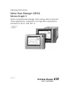
Safety Data Manager (SDM)
Memo-Graph S
System compatible data manager with a unique safety concept for
critical applications. Compliant to the high FDA requirements
laid down in the 21 CFR, Part 11.
8
BA 138R/09/en/08.04
No.: 51006049
Memo-Graph S
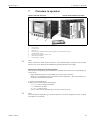
Overview
Your new Safety Data Manager (SDM) has the Operating Instructions built-in.
The device's simple control system enables you to commission for many applications, practically
without any paper. Your SDM displays instructions at the push of a button directly on screen.
This description is nevertheless delivered with the device - it is a supplement to the Operating
Instructions built into the device. Anything that is not described directly at the device by plain text
or menus is explained here.
!
Note!
We reserve the right to make alterations that contribute to technical progress. In this case, details
can differ from these Operating Instructions. No problem for you - your SDM has its Operating
Instructions built-in and is therefore always up-to-date.
Chapter 4 “Wiring” and Chapter 5 “Operation” explain how to wire the inputs and outputs and
how to program/set the associated functions.
Chapter 7 “Procedure in operation” explains how to use the configured device in operation, how
to call up which information and how to handle the replaceable memory (ATA flash card).
Brief overview
The following brief operating instructions will allow you to install and commission your device in
the correct order completely, quickly and easily:
Safety instructions
→ Page 7
Æ
Installation
→ Page 11
Incoming acceptance, transport, storage
Installation
Æ
Wiring
→ Page 13
Æ
Operation / adjusting device settings Set-up to commissioning
2
→ Page 23
Endress+Hauser
Memo-Graph S
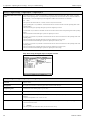
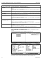
CHANGE PROTOCOL
CHANGE PROTOCOL
Safety Data Manager Memo-Graph S
Serial No.:
see original name plate on unit
Installed at (company / plant):
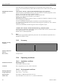
DOCUMENT REVISION HISTORY
Rev. #
Comment
Edited by
Date
Reviewed by
Date
1.0
First release
Kinzel
01/06/
2002
Sabine Eisenmann
01/06/
2002
1.1
Included description of Ethernet connection
Kinzel
01/03/
2003
Dieter Schmidt
01/03/
2003
1.2
Corrected fault in connection diagram
of RTD thermometers;
changed Chapter 3.3.2 "Panel mounting"
Kinzel
01/09/
2003
Dieter Schmidt
01/09/
2003
1.3
Documentation adapted to new corporate design;
included note regarding use of compact flash memory cards;
update accessories list
Seiffert
24/08/
2004
Madhukar Puniani
24/08/
2004
Document revision number 1.3, Stand 24.08.2004
Endress+Hauser
3
Memo-Graph S
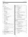
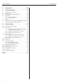
Table of contents
Table of contents
Overview . . . . . . . . . . . . . . . . . . . . . . . . . . . 2
5.4
Brief overview . . . . . . . . . . . . . . . . . . . . . . . 2
5.5
5.6
5.7
1
Safety instructions . . . . . . . . . . . . . . . . 7
1.1
1.2
1.3
1.5
Notes on safety conventions and icons . . . . . . . . . . .
Designated use . . . . . . . . . . . . . . . . . . . . . . . . . . . .
Installation, commissioning and operation . . . . . . . .
Return . . . . . . . . . . . . . . . . . . . . . . . . . . . . . . . . . . .
2
Identification . . . . . . . . . . . . . . . . . . . . 9
2.1
5.8
5.9
2.2
2.3
Device designation . . . . . . . . . . . . . . . . . . . . . . . . . 9
2.1.1 Nameplate . . . . . . . . . . . . . . . . . . . . . . . . . 9
2.1.2 Product structure . . . . . . . . . . . . . . . . . . . 10
Scope of delivery . . . . . . . . . . . . . . . . . . . . . . . . . . 11
Certificates and approvals . . . . . . . . . . . . . . . . . . . 11
3
Installation . . . . . . . . . . . . . . . . . . . . 11
5.10
3.1
3.4
Incoming acceptance, transport, storage . . . . . . . . .
3.1.1 Incoming acceptance . . . . . . . . . . . . . . . . .
3.1.2 Transport and storage . . . . . . . . . . . . . . . .
Installation conditions . . . . . . . . . . . . . . . . . . . . . .
3.2.1 Dimensions . . . . . . . . . . . . . . . . . . . . . . . .
Installation instructions . . . . . . . . . . . . . . . . . . . . .
3.3.1 Mounting kit . . . . . . . . . . . . . . . . . . . . . . .
3.3.2 Panel mounting . . . . . . . . . . . . . . . . . . . . .
Post-installation check . . . . . . . . . . . . . . . . . . . . . .
4
Wiring . . . . . . . . . . . . . . . . . . . . . . . . 13
4.1
4.2
Quick wiring guide . . . . . . . . . . . . . . . . . . . . . . . . 13
Terminal diagram . . . . . . . . . . . . . . . . . . . . . . . . . 15
4.2.1 Power supply board (slot 3) . . . . . . . . . . . . 15
4.2.2 Multifunction input boards 1 and 2 (on slot 1 or
2) . . . . . . . . . . . . . . . . . . . . . . . . . . . . . . . 16
4.2.3 Multifunction output board with relay (slot 2)
17
4.2.4 Digital input/output boards 1 or 2 (on slot 1 or
2) . . . . . . . . . . . . . . . . . . . . . . . . . . . . . . . 18
4.2.5 CPU board (slot 0) . . . . . . . . . . . . . . . . . . . 19
4.2.6 Front-mounted RS 232 interface* (jack plug) .
20
4.3.1 Ethernet connection . . . . . . . . . . . . . . . . . 21
4.3.2 Operating location . . . . . . . . . . . . . . . . . . . 22
Ingress protection class . . . . . . . . . . . . . . . . . . . . . 22
Post-connection check . . . . . . . . . . . . . . . . . . . . . . 22
3.2
3.3
4.4
4.5
7
7
7
8
11
11
11
11
11
12
12
12
12
5
Operation / adjusting device settings Set-up to commissioning . . . . . . . . . . . . . . 23
5.1
5.2
5.3
Basics on set-up directly at the device . . . . . . . . . . 23
Recommendation for commissioning and safe access
protection: . . . . . . . . . . . . . . . . . . . . . . . . . . . . . . 23
Access rights: . . . . . . . . . . . . . . . . . . . . . . . . . . . . 23
5.11
Beginning device configuration - Set-up (when unlocked) . . . . . . . . . . . . . . . . . . . . . . . . . . . . . . . . . . . 24
Set-up using PC . . . . . . . . . . . . . . . . . . . . . . . . . . . 26
Set-up using ATA flash card . . . . . . . . . . . . . . . . . . 27
List of operating parameters . . . . . . . . . . . . . . . . . . 27
5.7.1 Basic settings . . . . . . . . . . . . . . . . . . . . . . . 27
5.7.2 Signal settings . . . . . . . . . . . . . . . . . . . . . . 31
5.7.3 Signal analysis . . . . . . . . . . . . . . . . . . . . . . 47
5.7.4 Products . . . . . . . . . . . . . . . . . . . . . . . . . . 48
5.7.5 Texts . . . . . . . . . . . . . . . . . . . . . . . . . . . . . 50
5.7.6 Administration . . . . . . . . . . . . . . . . . . . . . . 50
5.7.7 Interfaces . . . . . . . . . . . . . . . . . . . . . . . . . . 51
5.7.8 Service . . . . . . . . . . . . . . . . . . . . . . . . . . . 53
Software update or upgrade via PC software . . . . . . 55
Communication via serial interfaces / modem . . . . 56
5.9.1 RS 232 . . . . . . . . . . . . . . . . . . . . . . . . . . . 56
5.9.2 RS 485 . . . . . . . . . . . . . . . . . . . . . . . . . . . 56
5.9.3 PROFIBUS DP . . . . . . . . . . . . . . . . . . . . . . 56
5.9.4 Commissioning a modem link . . . . . . . . . . 57
Set up Ethernet connection via internal interface . . 57
5.10.1 Menu: SETUP – Miscellaneous . . . . . . . . . 58
5.10.2 MAC address . . . . . . . . . . . . . . . . . . . . . . . 58
5.10.3 IP address allocation . . . . . . . . . . . . . . . . . 58
5.10.4 Subnet mask allocation . . . . . . . . . . . . . . . 59
5.10.5 Gateway allocation . . . . . . . . . . . . . . . . . . 59
Communication in the network via PC software . . . 59
6
Guaranteeing the requirements of
21 CFR 11 . . . . . . . . . . . . . . . . . . . . . . . . . . 61
6.1
6.2
6.3
General . . . . . . . . . . . . . . . . . . . . . . . . . . . . . . . . . 61
Important settings at the device . . . . . . . . . . . . . . . 62
6.2.1 Basic settings/operating modes . . . . . . . . . 62
6.2.2 Signal settings/digital outputs . . . . . . . . . . 62
6.2.3 Administration . . . . . . . . . . . . . . . . . . . . . . 63
6.2.4 Administration/create ID . . . . . . . . . . . . . . 63
6.2.5 Analogue inputs . . . . . . . . . . . . . . . . . . . . . 64
Important PC software settings . . . . . . . . . . . . . . . 64
6.3.1 General . . . . . . . . . . . . . . . . . . . . . . . . . . . 64
6.3.2 Activating the automatic read-out function and
autom. data storage . . . . . . . . . . . . . . . . . . 65
6.3.3 Activating the e-mail alarm . . . . . . . . . . . . 65
6.3.4 Activating automatic batch print-out . . . . . 66
7
Procedure in operation . . . . . . . . . . . . 69
7.1
7.2
Important functions in brief . . . . . . . . . . . . . . . . . . 70
The functions in detail . . . . . . . . . . . . . . . . . . . . . . 72
7.2.1 Logging in/out (“Login” key) . . . . . . . . . . . 72
7.2.2 Product selection (“Product” key) . . . . . . . 73
7.2.3 Enter comment / text . . . . . . . . . . . . . . . . 74
7.2.4 Displaying selected group of channels / measuring points . . . . . . . . . . . . . . . . . . . . . . . . . 74
7.2.5 Extras . . . . . . . . . . . . . . . . . . . . . . . . . . . . 74
7.2.6 Set-up . . . . . . . . . . . . . . . . . . . . . . . . . . . . 77
5
Table of contents
Memo-Graph S
8
Accessories . . . . . . . . . . . . . . . . . . . . 78
9
Trouble-shooting . . . . . . . . . . . . . . . . 79
9.1
9.2
9.3
9.4
Response of device to faults . . . . . . . . . . . . . . . . . 79
LED functions . . . . . . . . . . . . . . . . . . . . . . . . . . . 79
Searching for and eliminating faults . . . . . . . . . . . . 80
Spare parts . . . . . . . . . . . . . . . . . . . . . . . . . . . . . . 81
9.4.1 Spare parts diagram . . . . . . . . . . . . . . . . . 81
9.4.2 Spare parts list . . . . . . . . . . . . . . . . . . . . . 82
Disposal . . . . . . . . . . . . . . . . . . . . . . . . . . . . . . . . 84
Program / software update using program disk with the
help of operating and readout software . . . . . . . . . 84
9.6
9.7
10
10.1
10.2
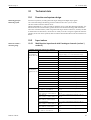
Technical data . . . . . . . . . . . . . . . . . . . . . . 85
Function and system design . . . . . . . . . . . . . . . . .
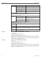
Input values . . . . . . . . . . . . . . . . . . . . . . . . . . . . .
10.2.1 Multifunction input board with 8 analogue
channels (socket 1, socket 2) . . . . . . . . . .
10.2.2 Digital I/O board (socket 1, socket 2) . . . .
10.2.3 Power supply board (socket 3) . . . . . . . . .
10.3 Output values . . . . . . . . . . . . . . . . . . . . . . . . . . . .
10.3.1 Multifunction output board (socket 2) . . . .
10.3.2 Digital I/O board (socket 1, socket 2) . . . .
10.3.3 Power supply board (socket 3) . . . . . . . . .
10.4 Power supply . . . . . . . . . . . . . . . . . . . . . . . . . . . .
10.5 Accuracy . . . . . . . . . . . . . . . . . . . . . . . . . . . . . . .
10.6 Operating conditions . . . . . . . . . . . . . . . . . . . . . .
10.6.1 Installation conditions . . . . . . . . . . . . . . . .
10.6.2 Environmental conditions . . . . . . . . . . . . .
10.7 Mechanical construction . . . . . . . . . . . . . . . . . . . .
10.8 Display and operating system . . . . . . . . . . . . . . . .
10.9 Data storage . . . . . . . . . . . . . . . . . . . . . . . . . . . . .
10.10 Certificates and approvals . . . . . . . . . . . . . . . . . . .
10.11 Accessories . . . . . . . . . . . . . . . . . . . . . . . . . . . . . .
10.12 Further documentation . . . . . . . . . . . . . . . . . . . . .
85
85
85
86
86
87
87
87
87
87
88
88
88
88
89
91
92
93
93
93
Index . . . . . . . . . . . . . . . . . . . . . . . . . . . . . 95
6
Memo-Graph S
1 Safety instructions
1
Safety instructions
1.1
Notes on safety conventions and icons
The devices are safely built and tested according to state-of-the-art technology and have left the factory in perfect condition as regards technical safety. The devices comply with the relevant standards
and guidelines as per EN 61010 “Safety requirements for electrical equipment for measurement,
control and laboratory use”. They can, however, cause danger if used improperly or other than
intended.
Always refer to the safety instructions in these Operating Instructions labelled with the following
symbols:
#
"
!
Warning!
“Warning” draws attention to activities or procedures that can lead to injuries to persons or to safety
risks if not carried out properly. Observe the work instructions closely and proceed with care.
Caution!
“Caution” draws attention to activities or procedures that can lead to defective operation or to destruction of the device if not carried out properly. Follow the instructions carefully.
Note!
“Note” draws attention to activities or procedures that have an indirect effect on operation, or can
trigger an unforeseen device reaction if not carried out properly.
1.2
Designated use
This device is suitable for installation in control panels and cabinets in non-hazardous areas. It meets
the requirements of EN 61010-1 / VDE 0411 Part 1 and has left the factory in perfect condition as
regards technical safety.
The manufacturer does not accept liability for damage caused by improper or non-designated use.
The device can cause danger if used improperly or other than intended. If it is obvious that safe operation is no longer possible (e.g. visible damage), please place the device immediately out of service.
Secure the device against unintentional start-up.
1.3
Installation, commissioning and operation
Observe the following points:
• Installation, electrical installation, commissioning and maintenance of the device must only be
carried out by trained experts who have be authorised to do so by the system operator. These
experts must have read and understood these Operating Instructions and follow their instructions.
• The device must only be operated by personnel who have been authorised and instructed by the
system operator. These Operating Instructions absolutely must be followed.
• Before connecting the device, ensure that the power supply corresponds to the value specified on
the nameplate. The installer is responsible for ensuring that the measuring system is correctly connected in accordance with the electrical wiring diagrams. Before switching on the system, again
check that all connections are correct.
• Primarily observe local regulations regarding opening and repairing electrical devices.
Endress+Hauser
7
1 Safety instructions
Memo-Graph S
1.4
"
Operational safety
Caution!
Operation is only guaranteed as safe when the instructions and warnings
in these Operating Instructions are observed:
• Only operate the device when it has been installed.
• Installation and connection require qualified experts. Please provide shock protection and connection in accordance with the valid safety regulations.
• The protective earth connection must be made before all other connections. Any interruption in
the protective earth can cause danger.
• Before commissioning, please compare the supply voltage with the information specified on the
nameplate.
• The mixed connection of safety extra-low voltage and dangerous contact voltage to the relay is
not permitted.
• Please provide a suitable switch or circuit breaker when installing in a building. This switch must
be installed near to the device (easily accessible) and be labelled as a separator.
• An overcurrent protective device (nominal current <= 10 A) is required for the power cable.
• If safe operation is no longer possible (e.g. visible damage) please place the device out of service
immediately and secure it against unintentional start-up.
• Repairs must only be carried out by trained customer service personnel.
Desk top version:
"
Caution!
• The mains plug must only be inserted into a socket with grounding contact.
• The protective effect must not be removed by an extension lead without ground wire.
• Relay outputs: U(max) = 30 V eff (AC) / 60 V (DC)
Repairs
Repairs that are not described in these Operating Instructions must only be carried out directly by
the manufacturer or by the service department.
Interference resistance
The measuring system meets the general safety requirements of EN 61010 and the EMC requirements of EN 61326.
Technical progress
The manufacturer reserves the right to adapt technical data to the most up-to-date technical developments without any special announcement. Ask your supplier for information about activities and
possible extensions to these Operating Instructions.
1.5
Return
The following measures must be taken before you return a measuring device, e.g. for repair or calibration:
• The device must be packed in protective packaging. The original packaging offers the best protection.
8
Endress+Hauser
Memo-Graph S
2 Identification
2
Identification
2.1
Device designation
2.1.1
Nameplate
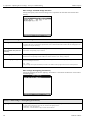
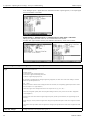
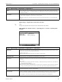
Compare the nameplate on the device with the delivery note and with the following diagram:
1
2
3
4
5
6
7
Figure 1:
1
2
3
4
5
6
7
Endress+Hauser
Nameplate data for the “Safety Data Manager”
Device designation
Order code
Device's serial number
Order number
Power supply data
Power consumption data
Patent no.
9
2 Identification
Memo-Graph S
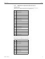
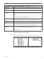
2.1.2
Product structure
Safety Data Manager
Inputs/outputs on slot 1
A
B
C
Slot 1 not used
8 Multifunction inputs (U, I, TC, RTD)
15 Digital inputs, 6 relays (NO contact)
Inputs/outputs on slot 2
A
B
C
D
E
Slot 2 not used
8 Multifunction inputs (U, I, TC, RTD)
15 Digital inputs, 6 relays (NO contact)
4 Analogue outputs, 6 relays (NO contact)
8 Analogue outputs, 6 relays (NO contact)
Power supply with inputs/outputs on slot 3
1
2
3
4
Power supply 115 to 230 V AC + 1 relay
Power supply 24 V AC/DC + 1 relay
Power supply 115 to 230 V AC + 7 digital / + 5 relay / + 1 open collector output
Power supply 24 V AC/DC + 7 digital / + 5 relay / + 1 open collector output
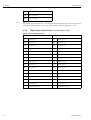
Interfaces
1
2
3
4
5
6
7
8
RS 232 interface
RS 485 and RS 232 interface
with ext. PROFIBUS-DP slave module
with ext. PROFIBUS-DP slave module and RS 485 interface
PROFIBUS-DP monitor 45.45 kBaud
PROFIBUS-DP monitor 93.75 kBaud
RS 232 and Ethernet interface
with ext. PROFIBUS-DP slave module and Ethernet interface
Internal memory
1
2
3
2048 kBytes memory, power failure secure
Works calibration certificate and 2048 kBytes memory, power failure secure
IQ-/OQ-template english works calibr. certificate incl. software backup f. unit +
Exchangeable memory
A
B
C
D
E
No memory card required
16 MB memory card
32 MB memory card
64 MB memory card
128 MB memory card
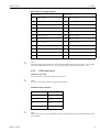
Unit bezel/operation/interface cable
A
B
C
D
Die-cast, IP54, door, glass window, front-mounted ATA flash, no cable
Stainless steel, IP65, no door, plastic screen, rear-mounted ATA flash, no cable
Die-cast, IP54, door, glass window, front-mounted ATA flash, with cable
Stainless steel, IP65, no door, plastic screen, rear-mounted ATA flash, with
Models
A
B
C
D
E
F
G
Panel-mounted unit without terminal or rear panel cover
Panel-mounted unit with terminal cover
Panel-mounted unit with rear panel cover
With desk top housing + Euro power cable
With desk top housing + Swiss power cable
With desk top housing + USA power cable
With IP65 field housing
Operating language
A
B
C
D
E
F
G
H
I
J
L
German
English
French
Italian
Spanish
Dutch
Danish
American English
Polish
Russian
Swedish
Unit software
A
C
Standard software incl. mathematics package
FO calculation incl. sterilisation/pasteurisation
Type
A
B
C
RSG12-
10
Standard version
ATEX II3G EEx nP IIC T4
Milk pasteurisation approval
⇐ Order code
Endress+Hauser
Memo-Graph S
3 Installation
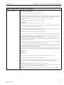
2.2
Scope of delivery
• Device (with screw plug-in terminals for mains and signal connection, according to your order)
• 2 jack screws
• 1 screwdriver, blade width of 2.5 mm
• PC operating and configuration software on CD-ROM
• Delivery note
• These Operating Instructions
• Memory card / floppy disk, in case it has been ordered
Anything missing? Then please inform your supplier.
2.3
Certificates and approvals
An overview of all certificates and approvals can be found in the Technical Data → Chapter 10.10
3
Installation
3.1
Incoming acceptance, transport, storage
3.1.1
Incoming acceptance
After receiving the goods, check the following points:
• Is the packaging or the contents damaged?
• Is the delivery complete? Compare the goods delivered with what you ordered.
3.1.2
Transport and storage
Observe the following points:
• The device must be packed in shockproof packaging for storage (and transport). The original
packaging offers the best protection for this.
• The permitted storage temperature is −20 to +70 °C (preferably +20 °C).
3.2
Installation conditions
Working temperature range:
0 to 50 °C, max. 57 % rel. moisture without condensation.
"
Caution!
• To avoid heat accumulation, please always ensure that the device is sufficiently cooled.
• Maintain distance from heavily magnetic fields (compare with Chapter 10 “Technical data”,
interference immunity )
• Environment at front in accordance with device ingress protection IP 54 (die-cast front with
closed door) or IP 65 / NEMA 4X (stainless steel front)
• The corresponding ingress protection is only guaranteed when the control panel seal is correctly
mounted.
3.2.1
Dimensions
The dimensions of the “Safety Data Manager” can be found in Chapter 10 “Technical data”.
Endress+Hauser
11
3 Installation
Memo-Graph S
3.3
Installation instructions
3.3.1
Mounting kit
To install the control panel, all you need is a screwdriver.
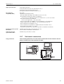
3.3.2
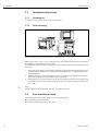
Figure 2:
Panel mounting
Panel mounting for version with die-cast or stainless steel front
Make a panel cutout, 138+1 x 138+1 mm in size (acc. DIN 43700). Please observe the asymmetrical alignment of the front bezel to the casing.
The installation depth of the device is approx. 211 mm without, or 232 mm with, rear panel or terminal cover.
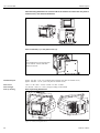
1.
2.
3.
!
Attach the control panel seal to the device and push it from the front through the panel cutout.
To avoid heat accumulation, we recommend keeping a distance of > 15 mm from the walls
and other devices.
Hold the device level and the hang jack screws in the openings (top/bottom or left/right for
IP54 ingress protection, all four for IP65 ingress protection).
Evenly tighten the screws on the jack screws using a screwdriver so that a secure, gap free seal
is guaranteed with the panel (recomended tension on the screws for an IP65 protection is 0.8
to 1.3 Nm).
Note!
Another support is only required for very thin control panel versions.
3.4
Post-installation check
After installing the control panel, please check the following points:
• Is the control panel seal mounted?
• Is the device fixed firmly in the control panel?
12
Endress+Hauser
Memo-Graph S
4 Wiring
"
Endress+Hauser
4
Wiring
4.1
Quick wiring guide
Caution!
Before wiring, please compare the supply voltage with the information specified on the nameplate.
If safe operation is no longer possible (e.g. visible damage) please place the device out of service and
secure it against unintentional start-up.
13
4 Wiring
Memo-Graph S
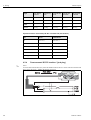
Analogue outputs (can be preset in set-up)
RL= Cable
resistance
RL
+
x15
8
3
x16
RxD/TxD(+)
RxD/TxD(_)
Further units
x16
+
I out
-
0...20 mA, 4...20 mA
-
x15
RS 485
RL= Cable
resistance
RL
+
x15
8
3
x16
RxD/TxD(+)
RxD/TxD(_)
Further units
x16
x16
5
1
6
To PC: Cable with
9 pol. Sub-D connector
9
7
14
13
25
2 3 5
To PC: Cable with
25 pol. Sub-D
connector
5
6
9
Rel.1
+
+
+
+
-
N
L
44
42
41
Rel.5 Rel.4 Rel.3 Rel.2
Ch.2
Ch.5
+ PE
+ N/L+
_
- L/L
+
+
-
53
54
63
64
73
74
83
84
DI 1
DI 2
DI 3
DI 4
DI 5
DI 6
DI 7
OC,max.
30V/100mA
Vout,max.
24V/100mA
Power
115...230 VAC
50/60 Hz
91
92
93
94
95
96
97
98
99
_
+
24 VAC/DC
0/50/60 Hz
+ (~)
PE
_
_ (~)
PE
max. 230 V / 3 A
Digital in (DI)
Digital out
(OC)
>20 ms
+
91
91
91
+24 VDC
100 mA
97
97
97
_
_
98
_
+
12..24 VDC
60 mA
>300 Ohm
99
Rel. 6...11 (term. 151...652) or rel. 12...17 (term. 751...C52) as with rel. 2...5 (term. 53...84)
To modem: Cable with
9 pol. Sub-D connector
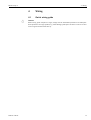
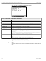
Note:
Sockets 1 and 2 can be fitted with either analogue input or digital output boards.
Socket 2 can be fitted with a multi-function output board.
Socket 3 is always fitted with the power supply board.
2 35
1
751
752
851
852
951
952
A51
A52
B51
B52
C51
C52
Socket 3
Power
supply
board
*Relay connections:
1
14
Ch.6
Ch.8
1
Ch.4
Ch.3
RS 422/485
RS 232
6
9
5
2 35
Ch.7
235
RS 485
Pin
RS 232
2
TxD
RxD RxD/TxD(+)
3
5
GND
RxD/TxD(-)
8
housing screen
screen
ATA - F l a s h
Only on stainless
steel bezel ATA-Flash
rear mounted
Option
Memory
Card
1
5
9
Option
Ethernet
6
1
LNK
A15
A16
B15
B16
C15
C16
D15
D16
E15
E16
F15
F16
G15
G16
H15
H16
Rel.17 Rel.16 Rel.15 Rel.14 Rel.13 Rel.12
Ch.1
RS422 see
operation
manual
Tx
24 VDC, max. 25 mA
x15
Socket 2
Socket 1
Analogue/ Analogue/digital*/
multi-function
digital*
output board
board
Rx
1...5 V, 0...10 V
+
x15 Loop power
supply
x16
-
111
112
113
114
211
212
213
214
311
312
313
314
411
412
413
414
511
512
513
514
611
612
613
614
711
712
713
714
811
812
813
814
U out
-
x15
+
CPU
board
+
7
13
25
To modem: Cable with
25 pol. Sub-D connector
x11 x12 x13 x14
x11 x12 x13 x14
Analogue inputs
x11 x12 x13 x14
Pt100:
Pt500:
Pt1000:
Ni100:
-100...+500 °C or -50...+150 °C
-100...+500 °C
-100...+500 °C
-60...+180 °C
screened cable
x11 x12 x13 x14
+
0...20 mA, 4...20 mA
+/- 1 mA, +/-2 mA, +/- 4 mA, +/- 20 mA, +/- 40 mA
Internal shunt: 50 Ohm
x11 x12 x13 x14
+
+/- 20 mV, +/- 50 mV, +/- 100 mV, +/- 200 mV
0...1 V, 0...10 V, +/- 1 V, +/- 2 V, +/- 5 V, +/- 10 V
+
-
Figure 3:
14
x11 x12 x13 x14
B (Pt30Rh-Pt6Rh):
0...+1820 °C
K (NiCr-Ni):
-200...+1372 °C
N (NiCrSi-NiSi):
-270...+1300 °C
S (Pt10Rh-Pt):
0...+1800 °C
U (Cu-CuNi):
-200...+600 °C
J (Fe-CuNi):
-210...+999,9 °C
L (Fe-CuNi):
-200...+900 °C
R (Pt13Rh-Pt):
-50...+1800 °C
T (Cu-CuNi):
-270...+400 °C
W3 (W3Re/W25Re): 0...+2315 °C
W5 (W5Re/W26Re): 0...+2315 °C
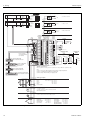
Connections/terminal diagram
Endress+Hauser
Memo-Graph S
4 Wiring
"
Caution!
Depending on the order, slots 1 or 2 can be fitted with different boards (with analogue and/or digital
inputs/outputs). Please carry out connection in accordance with terminal diagram.
4.2
"
Terminal diagram
Caution!
If high-energy transients occur when using long signal cables, we recommend
connecting a suitable overvoltage protection (e.g. E+H HAW 561 (51003570) and HAW 560
(51003571)).
Use screened signal cables for:
• Resistance thermometers, thermal elements and measuring ranges <1 V.
• Serial interfaces.
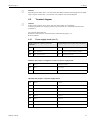
4.2.1
Power supply board (slot 3)
Supply voltage 115 to 230 VAC power unit,
50/60 Hz:
Supply voltage 24 VAC/DC power unit, 0/50/60 Hz:
L
Phase L
L+
+ supply voltage (or alternating voltage)
N
Zero conductor N
L-
- supply voltage (or alternating voltage)
PE
Earth/protective earth
PE
Earth/protective earth
Standard relay output* (changeover contact) on power supply board:
41
Relay 1
changeover contact
42
Relay 1
NC contact
44
Relay 1
NO contact
Optional relay outputs* on power supply board:
Endress+Hauser
53
Relay 2
contact 1
54
Relay 2
contact 2
63
Relay 3
contact 1
64
Relay 3
contact 2
73
Relay 4
contact 1
74
Relay 4
contact 2
83
Relay 5
contact 1
84
Relay 5
contact 2
15
4 Wiring
Memo-Graph S
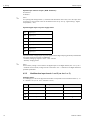
Optional open collector output* (NPN Transistor):
98 Collector
99 Emitter
!
Note!
The opening and closing function (= activation and deactivation of the relay coil or the open collector output) in case of a limit value can be defined in the set-up “Set-up - Signal settings - Digital
outputs (Relay / OC)”
Optional digital inputs on power supply board:
91
Digital input 1
92
Digital input 2
93
Digital input 3
94
Digital input 4
95
Digital input 5
96
Digital input 6
97
Digital input 7
Optional auxiliary voltage output on power supply board for digital inputs (galvanically isolated from
the system, short-circuit proof, not stabilised):
+ Auxiliary voltage typ. approx. +24 V / max. 100 mA
- Auxiliary voltage ground
!
Note!
If the auxiliary voltage is to be used for the digital inputs on the digital boards (slots 1 or 2), the “” terminal on the auxiliary voltage must be connected to the “-” terminal on the digital boards for
potential equalisation.
4.2.2
Multifunction input boards 1 and 2 (on slot 1 or 2)
Analogue inputs:
The first digit (x) of the three-digit terminal number corresponds to the associated channel (1.. to
8..: channels 1 to 8, or A.. to H..: channels 9 to 16).
Current
Voltage/Thermal elements
x11
A
x12
16
Resistance thermometer
+
x13
-
x14
+
a (scythe / expansion line)
B
Endress+Hauser
Memo-Graph S
4 Wiring
4.2.3
Multifunction output board with relay (slot 2)
Analogue outputs:
The first digit (x) of the three-digit terminal number corresponds to the associated
channel (1.. to 8..: channels 1 to 8, or A.. to H..: channels 9 to 16).
A15
+ Analogue output 1
A16
- Analogue output 1
B15
+ Analogue output 2
B16
- Analogue output 2
C15
+ Analogue output 3
C16
- Analogue output 3
D15
+ Analogue output 4
D16
- Analogue output 4
E15
+ Analogue output 5
E16
- Analogue output 5
F15
+ Analogue output 6
F16
- Analogue output 6
G15
+ Analogue output 7
G16
- Analogue output 7
H15
+ Analogue output 8
H16
- Analogue output 8
Relay outputs* on multifunction output board:
Endress+Hauser
751
Relay 12, contact 1
752
Relay 12, contact 2
851
Relay 13, contact 1
852
Relay 13, contact 2
951
Relay 14, contact 1
952
Relay 14, contact 2
A51
Relay 15, contact 1
A52
Relay 15, contact 2
B51
Relay 16, contact 1
17
4 Wiring
Memo-Graph S
!
B52
Relay 16, contact 2
C51
Relay 17, contact 1
C52
Relay 17, contact 2
Note!
The opening and closing function (= activation and deactivation of the relay coil) in case of a limit
value can be defined in the set-up “Set-up - Signal settings - Digital outputs (Relay / OC)”
4.2.4
Digital input/output boards 1 or 2 (on slot 1 or 2)
Digital inputs on digital board(s):
18
Digital board 1
Digital board 2
191
Digital input 8
391
Digital input 23
192
Digital input 9
392
Digital input 24
193
Digital input 10
393
Digital input 25
194
Digital input 11
394
Digital input 26
195
Digital input 12
395
Digital input 27
196
Digital input 13
396
Digital input 28
197
Digital input 14
397
Digital input 29
198
Digital input 15
398
Digital input 30
199
Digital input 16
399
Digital input 31
291
Digital input 17
491
Digital input 32
292
Digital input 18
492
Digital input 33
293
Digital input 19
493
Digital input 34
294
Digital input 20
494
Digital input 35
295
Digital input 21
495
Digital input 36
296
Digital input 22
496
Digital input 37
-
Digital board I ground
-
Digital board II ground
Endress+Hauser
Memo-Graph S
4 Wiring
Relay outputs* on digital board(s):
!
Digital board 1
Digital board 2
151
Relay 6, contact 1
751
Relay 12, contact 1
152
Relay 6, contact 2
752
Relay 12, contact 2
251
Relay 7, contact 1
851
Relay 13, contact 1
252
Relay 7, contact 2
852
Relay 13, contact 2
351
Relay 8, contact 1
951
Relay 14, contact 1
352
Relay 8, contact 2
952
Relay 14, contact 2
451
Relay 9, contact 1
A51
Relay 15, contact 1
452
Relay 9, contact 2
A52
Relay 15, contact 2
551
Relay 10, contact 1
B51
Relay 16, contact 1
552
Relay 10, contact 2
B52
Relay 16, contact 2
651
Relay 11, contact 1
C51
Relay 17, contact 1
652
Relay 11, contact 2
C52
Relay 17, contact 2
Note!
The opening and closing function (= activation and deactivation of the relay coil) in case of a limit
value can be defined in the set-up “Set-up - Signal settings - Digital outputs (Relay / OC)”
4.2.5
CPU board (slot 0)
Interfaces (rear side):
Sub-D connector as per DIN 41652, socket, nine pin
!
Note!
As a rule, unoccupied connections should be left empty.
Standard interface: RS 232*
!
Endress+Hauser
Pin
RS 232
2
TxD
3
RxD
5
GND
Housing
Screen
Note!
Please observe the correct pin assignment when connecting the rear-mounted RS 232 directly to a
PC or modem:
19
4 Wiring
Memo-Graph S
Signal
9-pin RS 232
to device
9-pin RS 232
to PC
25-pin RS 232
to PC
9-pin RS 232
to modem
25-pin RS 232
to modem
TxD
2
2
3
3
2
RxD
3
3
2
2
3
GND
5
5
7
5
7
Screen
Housing
(Housing)
(Housing)
(Housing)
(Housing)
Optional interface: alternatively RS 485 or Profibus DP (bus monitor)
Pin
RS 485
PROFIBUS-DP
3
RxD/TxD (+)
RxD/TxD (+)
RxD/TxD (-)
RxD/TxD (-)
Screen
Screen
4
5
8
9
Housing
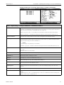
4.2.6
!
Note!
The front-mounted interface only comes as standard with the device version with die-cast front and
door, not for the IP 65 / NEMA 4X stainless steel front.
Figure 4:
20
Front-mounted RS 232 interface* (jack plug)
Front-mounted interface RS232
Endress+Hauser
Memo-Graph S
4 Wiring
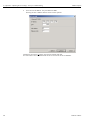
4.3
Connecting a device to the Ethernet (TCP/IP)
In principle, all devices equipped with an internal Ethernet interface can be integrated into a PC
network (TCP/IP Ethernet).
The device(s) can be accessed by any of the PCs in the network using PC software. It is not necessary
to install driver software ("COM redirection") on the PC because the PC software has direct access
to the Ethernet.
The system parameters "IP address", "Subnet mask" and "Gateway" are input directly at the device.
Changes to the system parameters are not activated until the SETUP menu is closed and the settings
accepted. Only then will the device work with the new settings.
!
Note!
It is not possible for several clients (PC) to communicate with a server (device) at the same time. If
a second client (PC) tries to establish a connection, he receives an error message.
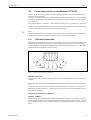
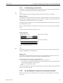
4.3.1
Ethernet connection
An IEEE 802.3 compatible connector on a screened RJ45 plug on the rear side of the device is available as a network connection. The device can be connected to a hub or switch via this connection.
The pin assignment corresponds to a standard MDI interface (AT&T258), so that a 1:1 cable with a
maximum length of 100 metres can be used here.
Figure 5:
RJ45 socket (pin assignment AT&T256)
Meaning of the LED’s
There are three LEDs next to the Ethernet connections. These indicate the status of the Ethernet
interface.
Yellow LED: When the device is transmitting data it flashes irregularly, otherwise is continuously
on.
Green LED: When the device is receiving data it flashes irregularly, otherwise is continuously on.
Red LED: Is on when the device is connected to a network. If this LED is not illuminated then communication is impossible.
The following standards are supported:
10BaseT, 10 MBit/s
The devices function according to the 10BaseT standard with 10MBit/s. It is, however, also possible to integrate the device into a 100BaseTx network via an auto-sensing hub or switch. This kind
of auto-sensing component sets itself automatically to the transmission rates supported by the end
device.
Endress+Hauser
21
4 Wiring
Memo-Graph S
4.3.2
Operating location
The operating location of the device should be selected such that the network-specific maximum
permitted cable length of 100 metres is not exceeded.
Please ensure that all connections are inserted only when the end devices are switched off.
4.4
Ingress protection class
The device with stainless steel front meets all the requirements of ingress protection IP65
(NEMA 2x). The device with metallic die-cast front and door meets all the requirements of ingress
protection IP54 (NEMA 4x).
4.5
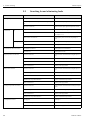
Post-connection check
After completing the device's electrical connections, carry out the following checks:
22
Device status and specifications
Notes
Is the device or cable damaged (visual inspection)?
−
Electrical connection
Notes
Does the supply voltage match the information on the nameplate?
Compare nameplate on the
device
Are the mounted cables relieved of tension?
−
Endress+Hauser
Memo-Graph S
5 Operation / adjusting device settings - Set-up to commissioning
5
Operation / adjusting device settings Set-up to commissioning
5.1
Basics on set-up directly at the device
• The function of the operating keys is described in the fields directly above the corresponding keys
on the screen. Empty fields mean that the corresponding keys currently have no function.
• Access to the set-up is released ex works and can be locked in various ways:
– Entering a 4-digit release code (see Chapter 5.7.1 “Basic settings”)
– Clear password / ID combinations for administrator and user (see Chapter 5.7.6 “Administrator”)
– Activating a digital input (see Chapter “Signal settings - Digital inputs”)
– Attaching the rear panel cover with leaded sealing.
• When locked, basic settings can be checked. Users can not make any changes. An administrator
however, who is defined during commissioning, can make the following changes:
– Adding or deleting new or already registered users (e.g. new employees or employees who have
left the company)
– Adding, changing or deleting texts / comments. Comments that have already been saved are
not affected by this
"
Caution!
After changing settings that affect the measured value memory (recognisable by the
“ * ” symbol in the header), the measured value memory is deleted. If the previous measured values
are still required, please update the ATA flash card and take these values, or read out the device
using an interface. Afterwards, end the set-up. When the new set-up data is adopted, the old measurement data in the memory and on the ATA flash card is deleted, the device is reset and restarted.
5.2
1.
2.
3.
!
4.
5.3
!
Recommendation for commissioning and safe access
protection:
Set the corresponding parameters or load a parameter set onto the device.
Enter a release code (or activate a control input in order to lock access to the set-up), start and
check that the device is functioning properly.
After the operational test has been successfully completed, register an administrator and a user
if required (see “Administration”).
Note!
There always has to be an administrator registered before he himself can define users.
Attach the rear panel cover and seal it. This prevents any further change to the device settings.
Use of the interface(s) is thereby only possible in read-only mode.
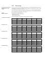
Access rights:
Note!
The availability of the rear panel cover is monitored with the help of a light barrier. This monitoring
can be activated/deactivated using the device software. Depending on the setting, the administrator
or the user has access rights to the set-up, in order to change the settings. When locked, the settings
in the set-up can only be read:
In principle, the device settings can only be read. The set-up can only be changed under
certain conditions (see table).
Endress+Hauser
23
5 Operation / adjusting device settings - Set-up to commissioning
Checking the
rear panel cover
OFF
Rear panel cover
mounted
Independent of
whether mounted
or not mounted
Memo-Graph S
ID and password
system activated
Logged in
No
Function not available
Yes
-
No
Administrator
Yes
User
No
Function not available
No
-
No
Administrator
No; Administration possible
User
No
Function not available
Yes
-
No
Administrator
Yes
User
No
Yes
No
Yes
Yes
ON
No
Set-up changes
permitted
No
Yes
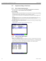
5.4
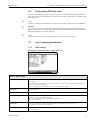
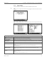
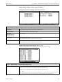
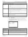
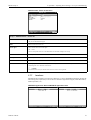
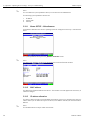
Beginning device configuration - Set-up (when unlocked)
• Press “Set-up”: the main menu is displayed
• Use “↑” or “↓” to select the desired chapter
• Use “↵” to confirm your selection
• Use “Help” to hide or show the integrated Operating Instructions (help text in yellow frame) at
any time.
• Use “ESC” to undo the entry
• Use “New” to delete a text before making your entry
24
Endress+Hauser
Memo-Graph S
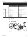
5 Operation / adjusting device settings - Set-up to commissioning
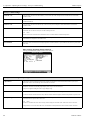
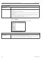
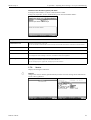
The main menu:
!
Note!
If individual chapters are missing, your device is not equipped with this option.
The individual parameters are summarised in the main menu in chapter:
Basic settings see Chapter 5.7.1
– General parameters (date, time, release code ...)
Signal settings see Chapter 5.7.2
–
–
–
–
All parameters related to the channel or measuring point in the analogue and digital inputs / outputs
Parameters for combining analogue and digital inputs (depending on the order)
Behaviour of the relay in quiescent state
Parameters for summarising/presenting individual channels into groups
!
Note!
Only channels that are assigned to a group can be displayed and saved (internal memory and on ATA flash
card).
Channels that are not assigned to any group can nevertheless be monitored for limit value violation or automatically
analysed (select this, for example, to make optimum use of the memory capacity).
Signal analysis see Chapter 5.7.3
All settings that are required in order to automatically analyse the signal.
!
Note!
The signal analyses are also saved and can be used further on the PC. This enables you, for example, to access daily
minima, maxima, averages from less important measuring points on site and display them on the PC in a table or
“strung together” as a curve sequence. Helps to optimise use of the memory capacity.
Products see Chapter 5.7.4
Settings for products managed by the device, including product-related limit values
Texts see Chapter 5.7.5
List of recurring texts that are selected by users as comments for recording and which can then be saved.
!
Note!
Can be accessed by the administrator, even when the rear panel cover is attached.
Administration see Chapter 5.7.6
Settings for registering and deleting administrators and users, and allocated ID codes.
!
Note!
Can be accessed by the administrator, even when the rear panel cover is attached.
Interfaces see Chapter 5.7.7
Settings for device-internal interfaces
Service see Chapter 5.7.8
General service functions,
ONLY FOR SERVICE PERSONNEL; when the rear panel cover is attached, the administrator has to provide
the service technician with access.
Key functions for selecting/changing:
• “↵”: beginning of change, confirmation of selection
• “↓” or “↑”: selects parameters
• “←” or “→”: moves cursor - switches to the next symbol
• “ESC”: cancels the last operating step -> returns to previous screen
Endress+Hauser
25
5 Operation / adjusting device settings - Set-up to commissioning
Memo-Graph S
Input principle:
1. Begin changing each parameter with “↵”.
2. Use “↓” or “↑” to leaf through values, symbols, selection lists.
3. If the parameter is set correctly, use “↵” to confirm.
!
Note!
– Any settings that are displayed in grey can not be selected / can not be changed (only notes, or
option not available/not activated).
– With the factory setting “0000” (delivery status), configuration is possible at any time. It can be
protected against unauthorised manipulation by entering a 4-digit release code. This has to be
entered when the settings are later changed, if the device settings are to be changed by keyboard.
Tip: make a note of your release code. Store it somewhere where unauthorised persons do not have
access to it.
– The changed settings do not become effective until you return to normal operation by repeatedly pressing “ESC” and confirming with “↵”. Until this time, the device still works with the
previous data.
5.5
Set-up using PC
You can also put your Safety Data Manager into service and/or configure it via PC. The following
are available for this:
– Front-mounted RS 232 operating interface (3.5 mm jack plug, stereo, protected behind the unit
cover; only available with die-cast front - not with stainless steel front)
– Rear-mounted RS 232 or RS 485 system interfaces (depending on scope of delivery)
!
Note!
You can use the PC software ReadWin® 2000, which is provided with the Safety Data Manager, to
put the device into service / configure it via PC. You can also download the software directly from
the internet under the followingg address:
www.endress.com/readwin
For further information on ReadWin® 2000, refer to the operating manual of the software
(BA107R/09).
Installation of PC software:
1.
2.
"
3.
4.
Install the supplied PC software on your computer. The program's Operating Instructions can
be printed out after installation, if required.
Call up the program.
Caution!
Please make the plug connection first, then the connection to your PC. When removing the
connection, proceed in reverse order.
Now you can configure your device via PC. For this, please refer to the program's instructions/help.
Advantages of configuration via PC:
• The device data is saved in a database and can be accessed again at any time.
• Text entries can be carried out more quickly and efficiently by keyboard
• Measured values can also be read out, archived and displayed on the PC with this program.
"
26
Caution!
Configuration can only be carried out via one interface (RS 232 or RS 485) at a time.
Endress+Hauser
Memo-Graph S
5 Operation / adjusting device settings - Set-up to commissioning
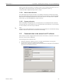
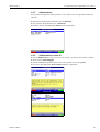
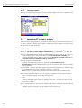
5.6
Set-up using ATA flash card
Save the device settings on the PC onto the ATA flash card using the operating and readout software. This set-up file can be adopted into the device, if released, under “Extras - ATA flash - Load
ATA flash set-up”.
!
"
!
Note!
In order to be able to use this function, the device must already be registered in the PC database.
Caution!
If the set-up ATA flash card is not removed, the measurement data will begin to be saved after
approx. 5 minutes. The set-up data is still kept. Please change the ATA flash card if the measurement
data is not meant to be saved onto this card.
Note!
The functions described above are also valid for the use of Compact Flash cards.
5.7
List of operating parameters
5.7.1
Basic settings
Settings that are generally valid, e.g. date, time, etc.
Set-up -> Basic settings
Device designation
Use this to describe, for example, where the device is installed (important if you are using several devices). 20 characters.
!
Note!
Is also saved onto the ATA flash card. In the PC, graphics/tables are provided with this text (important, for example, if
you have several devices in operation).
The device designation is also available for the export, e.g. in a spreadsheet program.
Current date
Format: DD.MM.YY
Current time
Format: hh:mm, 24 h display
Summertime changeover
Function of summertime / normal time changeover.
“Automatic”: changeover as per valid EC directives
“Manual”: Set the changeover times in the next operating positions
“Off”: no time changeover
NT/ST Region
In Europe, the summertime / normal time changeover takes place at different times to that in the USA.
Select the region in which the device is installed.
Date NT -> ST
Day in spring on which the changeover from normal time to summertime takes place.
Format: DD.MM.YY
Endress+Hauser
27
5 Operation / adjusting device settings - Set-up to commissioning
Memo-Graph S
Set-up -> Basic settings
Time NT -> ST
Time at which the time is moved forward by 1 hour on the day of the changeover from normal time to summertime.
Format: hh:mm
Date ST -> NT
Day in autumn on which the changeover from summertime to normal time takes place.
Format: DD.MM.YY
Time ST -> NT
Time at which the time is moved back by 1 hour on the day of the changeover from summertime to normal time.
Format: hh:mm
Release code
Ex works: “0000”, i.e. device can be set at any time without release code.
Individual code set: device can only be set after entering this code.
!
Note!
Make a note of the code and store it somewhere where it is inaccessible to unauthorised persons.
Temp. unit
Selecting the temperature unit. All directly-connected temperature measurements with thermal elements or resistance
thermometers are displayed in the defined unit.
Text thickness
Defines in which line thickness the analogue signals are recorded (normal =1 point with thin text; bold = 2 points with
wide text).
Basic settings: Operating modes sub-menu
Settings that determine the functions of the device.
Set-up -> Basic settings -> Operating modes
Open circuit
The directly-connected thermal elements and resistance thermometers can be monitored for breaks in cycles by an
impressed current. This monitoring can be switched on or off here.
Open circuit value
Selection: lower limit stop or upper limit stop.
Measured value that is set for the graphic display when an open circuit is detected.
Jump in the signal recording on lower or upper display range.
Limit values
“Product-related”: the limit value monitor is only active when a product is running.
“Channel-related”: the limit values are only effective from the measured signals, therefore independent of a product run.
ATA operating mode
“Stack memory”: if the ATA flash card is full, no further storage onto this card can be carried out until it has been read
out and deleted or replaced with a new card.
!
Note!
In order to avoid data loss or to switch a relay, further settings can be made under “Data carrier full” for this case.
“Ring memory”: if the ATA flash card is full, the oldest data is always deleted in order to make room for new data.
28
Endress+Hauser
Memo-Graph S
5 Operation / adjusting device settings - Set-up to commissioning
Set-up -> Basic settings -> Operating modes
LED operating mode
Namur “NE44”: the signalling through the front-mounted LEDs complies with NAMUR guideline NE 44.
Green LED lights up: power supply OK
Red LED lights up: measurement signal failure.
Red LED flashes: maintenance required, e.g. messages to be acknowledged, calibration ....
Namur “NE44+”: same as Namur “NE44” + limit values.
The signalling through the front-mounted LEDs complies with NAMUR guideline NE 44, however the red LED is used
additionally to indicate limit value violations.
“Controlled with a digital input”: (the digital input is activated in signal settings, digital inputs as control input with the
effect that H->green, L->red LED or L->green, H->red LED.)
“Controlled with two digital inputs”: (both digital inputs are activated in signal settings, digital inputs as control input
with the effect that green is the operating LED and red the fault LED.)
Batch mode
“Not used”: batch functions switched off.
“Automatically increase”: for every product start, the batch number for this product is automatically increased by 1 and
saved when the batch is finished.
!
Note!
The batch number can be reset to zero if required via a control input (see “Control inputs”)
“Manual”: the batch designation (20 characters) can be entered manually at the device via an input mask for every batch
(Product ->Batch).
(File) Encryption
“Maximum”: historical values are completely encrypted, so that the interpretation of the historical data saved on the ATA
flash card can only be interpreted by the PC software package supplied by the equipment manufacturer.
“Standard”: the historical data saved on the ATA flash card can also be used and interpreted by foreign programs. This
passes over responsibility for data consistency between the point of acquisition and the display to the supplier of the
foreign software.
Rear panel cover
“check”: the availability of a rear panel cover is checked and logged.
“do not check”: checking whether rear panel cover is available or not, is deactivated.
Basic settings -> Operating modes: Recalibration sub-menu
This function enables simple recalibration of an entire measurement section (sensor/transmitter Cable - Safety Data Manager). When activated, the complete measurement section (Sensor - Transmitter - Cable - Terminals - Measuring input) can be recalibrated in normal operation on site.
Set-up -> Basic settings -> Operating modes -> Recalibration
Active
“No”: recalibration not active. Function is not used
“Always”: recalibration always active . Function can always be used.
“Without rear panel cover”: only the administrator responsible can carry out this function.
“With rear panel cover”: users or administrators responsible can carry out this function.
Access rights
“Anyone”: recalibration can be carried out by anyone.
“Only administrator”: recalibration can only be carried our by the administrator.
!
Note!
Access can also be made only to authorised personnel. Access is not enabled and incorruptibly documented when password / ID is entered.
Endress+Hauser
29
5 Operation / adjusting device settings - Set-up to commissioning
Memo-Graph S
Basic settings: ATA flash change sub-menu
Settings that specify when/how the filling level is reported to an ATA flash card used as stack
memory.
Set-up -> Basic settings -> ATA flash change
Warning at xx %
Warns before ATA flash card is 100 % full. The internal (ring) memory is still written on during the change or when the
ATA flash card is full. This new data is copied onto the new or readout and deleted ATA flash card after changing the card
(important for complete archiving).
Warning after xxx minutes without ATA flash card (max. 999
minutes)
If you forget to insert a new card when changing the ATA flash card, a warning appears on the screen after the defined
time and the corresponding relay is switched.
Switching output
If the warning message “Data carrier full/missing” is displayed, a relay or an open collector output can be additionally
activated. The corresponding terminal numbers are shown in brackets. (See “Wiring” Chapter 4)
Acknowledging warning
“Yes”: the warning “Data carrier full/missing” remains displayed until it is acknowledged by pressing the button.
“No”: the message is not shown
!
Note!
The percentage of occupied card memory is shown in the header at the top right of the screen in normal operation.
Basic settings: Back lighting (Screensaver)
Setting for switching off the back lighting (“Screensaver”: screensaver increases the service life of
the back lighting).
Set-up -> Basic settings -> Back lighting (Screensaver)
Lighting out after ...
30
Switches display dark xxxx minutes after the last keyboard activity (back lighting is switched off). All further functions
are kept (green LED lights up). Press any key to switch the lighting back on.
“0000 min” = does not switch off
“9999 min” = switches off after 6 days, 22 hours and 39 minutes
Endress+Hauser
Memo-Graph S
5 Operation / adjusting device settings - Set-up to commissioning
5.7.2
Signal settings
Settings, groupings and combinations for analogue and digital inputs and outputs.
!
Note!
Values can only be changed if the authorised person is logged in, otherwise the values can only be
looked at.
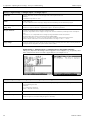
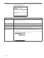
Signal settings: Analogue inputs sub-menu:
View or change settings/limit values of connected measuring points for analogue measured variables.
Set-up -> Signal settings -> Analogue inputs -> Analogue input x
Signal
Can be selected per channel. See also “Connections/terminal diagram”.
Channel identification
Designation of the measuring point connected to this channel. 10 characters.
Engineering units
Entry for technical (physical) unit for the measuring point connected to this input (e.g. bar, °C, m3/h, ...). 5 characters.
Decimal point
Number of places after decimal point for the 4-digit measured value display.
Measuring range zero
*Transmitters convert the physical measured variable into standardised signals.
Example:
0-14 pH of the sensor are transformed into 4-20 mA. Enter the start of the measuring range here.
At 0-14 pH, therefore, “0”.
Measuring range span
Used in the same way as “Measuring range zero”. However here the end of the measuring range is entered.
Example:
“14” for a transmitter of 0-14 pH
Zoom start
*If the entire transmitter range is not used, you can specify the lower value of the required section (with this you can
achieve a higher resolution).
Example:
0-14 pH transmitter, required 5-9 pH section. Set “5” here.
Endress+Hauser
31
5 Operation / adjusting device settings - Set-up to commissioning
Memo-Graph S
Set-up -> Signal settings -> Analogue inputs -> Analogue input x
Zoom end
Same as “Zoom start”. However, enter the upper value of the required section here.
Example:
Transmitter 5-9 pH. Enter “9” here.
Offset
Factory setting “0”.
Set value is added for further use (display, storage, limit value monitoring) for real measured input signal.
Interference suppression (damping / filter)
The more undesired interferences superposed on the measuring signal, the higher this value should be set. Result: quick
interference surges are attenuated / suppressed (for experts: “1st order low-pass filter”).
Hot pin calibration
Position only available for direct connection of thermal elements.
“Internal”: compensation of error voltages occurring at the connection terminals by measuring the back wall temperature.
“External x °C/°F”: compensation of error voltages by using thermostatic external cold junctions.
Recommendation when using type B thermal elements (Pt30Rh-Pt6Rh):
Always set “External (0 °C / 32 °F)”, even when using direct connection without external cold junction.
Reason: unlinear characteristic curve of this thermal element in the range of < 50 °C / < 122 °F.
Copy settings
Copies the settings of the current channel into the selected channel (including limit values). Both of the last positions of
the target channel's designation are replaced with its channel number.
Signal settings -> Analogue inputs -> Analogue input x: Integration sub-menu:
Settings only required if this analogue measuring point is to be integrated - e.g. for quantity calculation. Analysis times can be set under “Signal analysis” (see Chapter 5.7.3).
Set-up -> Signal settings -> Analogue inputs -> Analogue input x -> Integration
Integration basis
The quantity (here in m3) can be calculated from an analogue signal (e.g. flow in m3/h) using integration. Here, select
the corresponding time basis.
Examples:
l/s -> time basis in seconds (s);
m3/h -> time basis in hours (h).
Unit integrated
Here, enter the unit of the quantity determined using integration (e.g. “m3”).
Display alternately
Selection of whether and which counter is to be displayed alternately with the current value. The analogue value is then
shown for approx. 6 s, the meter reading for approx. 4s alternately.
32
Endress+Hauser
Memo-Graph S
5 Operation / adjusting device settings - Set-up to commissioning
Signal settings -> Analogue inputs -> Analogue input x: Profibus DP sub-menu (Option
Listener / Monitor):
Settings only required if the measured values for this channel are to be acquired using the data interface (and not by an analogue input).
!
Note!
This option can only be seen if the device has been ordered with the “Profibus DP Monitor” option
and has been activated under “Interfaces - Data interface - DP bus monitor”.
Set-up -> Signal settings -> Analogue inputs -> Analogue input x -> Profibus DP (Option Listener / Monitor)
Slave address
Select the address of the corresponding sensor. Every sensor, “Slave”, must have its own, individual address. The measured value (of the digital bus signal) is treated in the same way as conventional analogue measuring points.
!
Note!
If a slave delivers several measurement data sets (“Input Index Data” for multi-parameter sensors), each channel requires
its own channel.
Input_Data index
Position where the measured value information in the PROFIBUS transmitter data set begins. For one channel devices:
“000”. Please also refer to the Operating Instructions of the connected sensor.
Data type
Mainly “Floating Point”. Please refer to the Operating Instructions of the connected sensor.
Signal settings -> Analogue inputs -> Analogue input x: Profibus DP sub-menu (slave
option):
!
Endress+Hauser
Note!
This menu is only available if an external Profibus module is connected to the Safety Data Manager.
Before the corresponding analogue input can be set, the “external Profibus-DP slave module” data
interface must be set in the set-up under interfaces.
33
5 Operation / adjusting device settings - Set-up to commissioning
Memo-Graph S
In the analogue inputs / signal menu the “from data interface” option appears, i.e. the input signal
is sent via Profibus to the SDM.
Signal settings -> Analogue inputs -> Analogue input x: Limit value x sub-menu:
Settings only required if limit values are to be monitored for this channel.
If a limit value type has been selected, it is marked as activated by “Limit value created”.
Set-up -> Signal settings -> Analogue inputs -> Analogue input x -> Limit value x
Type
Select the type of limit value.
Analogue signals:
“Upper limit”: signal exceeding limit value.
“Lower limit”: signal undershooting limit value.
“Gradient”: signal changing too quickly.
for quantities (calculated from the analogue signal using integration): the limit value of the meter reading is exceeded
within the specified period of time.
!
Note!
In order to be able to monitor meter readings for limit value violation, the corresponding signal analyses must be activated (see Chapter 5.7.3 “Signal analysis”).
Limit value, upper/lower: analogue limit value in the set process unit, e.g. in °C, bar, ... .
Limit value, integrated: quantity limit value (integrated analogue channel) in the process unit set under “Integration”
(“Unit integrated”).
Gradient dy/dt: limit value when the signal changes too quickly (within a period of time dt, the signal changes by the
value dy).
Signal change dy: value by which the signal has to change in the specified time span in order to be recognised as a limit
value.
Time span dt: time span within which the signal has to change by the specified value in order to be recognised as a limit
value.
Limit value, analogue
34
Analogue limit value in the set process unit, e.g. bar, °C
Endress+Hauser
Memo-Graph S
5 Operation / adjusting device settings - Set-up to commissioning
Set-up -> Signal settings -> Analogue inputs -> Analogue input x -> Limit value x
Hysteresis type
“percentual %”: set hysteresis in %. “absolute”: specify hysteresis in the set process unit (e.g. in °C, bar, ...).
Hysteresis value
The limit value status is not deactivated again until the signal is back to the normal range again by the value set here.
Time delay
The signal must exceed or undershoot the specified value for at least the set time in order to be interpreted as a limit
value.
Alarm output
Switches the corresponding relay in limit value status (or the open collector output). The terminal numbers are shown in
brackets. Please refer to the connection instructions (see “Safety instructions/type-related use” or “Connections/terminal diagram”).
!
Note!
• In case of a limit value, the relay is activated. For this, the relay contact is switched or closed at the factory (relay
1)/(relays 2-5) or the open collector is connected through.
• This operating mode can be inverted if required under “Digital outputs / Relays / OC”.
Alarm text on
This text is (with date and time) shown on the screen if the limit value is violated and “LV messages” is set to “display+acknowledge”. Use this function, for example, as a brief procedure instruction for the operator on site.
Alarm text off
Same as “Alarm text on”, but for returning from the limit value mode into normal operation.
Alarm messages
“Display+acknowledge”: message on the display must be acknowledged by pressing the key (“OK”). It consists of the
date, time and channel identification with limit value (alternatively alarm text on/off, if a text has been entered there).
“Do not display”: limit value is displayed with a measuring point designation with red background.
Store limit value
“Normal”: storage in normal memory cycle (setting under “Signal grouping - Memory cycle”).
“Alarm cycle”: memory cycle in case of limit value (setting under “Signal grouping- Alarm cycle”), e.g. in seconds.
!
Note!
Increased memory requirement
Signal settings: Digital inputs sub-menu (Option):
!
Endress+Hauser
Note!
Settings only required if digital inputs (option - e.g. for counter / events) are to be used.
35
5 Operation / adjusting device settings - Set-up to commissioning
Memo-Graph S
Set-up -> Signal settings -> Digital inputs -> Digital input x
Function
Activation of the input triggers the set function. The digital inputs are high-active, i.e. the selected effect is achieved by
activation with +12 to +30 VDC. See also Chapter 4.2 “Connections/terminal diagram”.
!
Note!
Depending on the selected function, the device's user interface adapts itself, so that each time only parameters that are
required for safe device functioning have to be checked/set.
“Control input”: for remote control of certain device functions that are activated via binary signals. For list, see “Type of
control input”
“Impulse counter”: for counting and adding quantity-proportional pulses.
“On/off events”: for recording edge changes, i.e. in order to save the current time at which this digital input has been
activated or deactivated.
“Operating time”: for acquiring run times. The entire run time is cumulated, saved in cycles that can be set and reset. See
also see Chapter 5.7.3 “Signal analysis”.
Example:
If the daily run time of a pump is to be saved, activate “Operating time” here and “Daily analysis” under “Signal analysis”.
“Event+operating time”: combination of the “Events” and “Operating time” functions described above. With this, you
can also acquire the on-time and off-time as well as the cumulated run time.
Designation
36
Description of the function or measuring point name carried out with this input. 10 characters.
Endress+Hauser
Memo-Graph S
5 Operation / adjusting device settings - Set-up to commissioning
Set-up -> Signal settings -> Digital inputs -> Digital input x
Effect of the control input
Only when used as control input:
triggers the allocated control function on the device when activated.
“only record”: the control input has no function, it is just recorded.
“External intermediate analysis”: as long as the control input is activated all active channels are analysed, i.e. the analysis
of min./max. averages is not made in cycles in fixed intervals / intermediate analyses, rather it is controlled via this digital input. The analysis starts when the input is activated. It is completed and saved when deactivated.
Example:
Acquiring minima, maxima, averages and quantities of a batch production.
#
Warning!
Under “Signal analysis”, “Intermediate analysis” must be set to “external”.
“Lock set-up”: as long as the control input is activated, the “Set-up” key is not accessible. The set parameters can not be
displayed or changed until the control input deactivated again.
“Show text”: the specified text is shown in a message box, as long as the input is activated. If “Text, 1st part” and “Text,
2nd part” have been filled in, both parts are displayed together in the box.
Tip:
Use this, for example, as a brief procedure instruction for the operator on site.
“Display group”: the display switches to the selected group when the input is activated (signal leap from Low to High).
“Display dark”: as long as the input is activated, the display's back lighting is switched off. The device's remaining functions (e.g. storage, limit value monitoring, etc.) are not affected by this.
“Synchronise time”: when the input is activated (signal leap from Low to High), the internal second counter is set to
zero. If the second indicator is between 0 and 29, the minutes remain unchanged. If the second indicator is between 30
and 59, the minutes are increased by one.
Tip:
Use this function in conjunction with a master clock. All devices used in this way run synchronously. Any signals measured on different devices can be clearly compared with each other chronologically.
“Product Start/Stop”: indicates when the production of a previously selected product starts / stops. If product-specific
has been selected in “Basic settings - Operating modes - Limit values”, those limit values allocated to the selected product
are monitored as long as this digital input remains activated.
“Product selection (BCD)”: here the product is selected via a binary coded signal. For this, every digital input required
must be set to “Product selection (BCD)”. The lowest position is automatically allocated to the lowest free digital channel:
Digital input 1 = 20
Digital input 2 = 21
Digital input 3 = 2²
Digital input 4 = 2³
“Save text”: when the input is activated, a previously selected text ( see text selection (BCD) ) is saved.
“Text selection (BCD)”: here the text is selected via a binary coded signal.
“Save curve”: as long as this input is activated, the activated channels are also recorded under “Signal settings - Form
groups - Memory cycle”, i.e. the screen display and storage of the signal recording are controlled externally.
!
Note!
• The limit value monitoring also functions when this input has not been activated.
• Use this function (input not activated), e.g. if you do not want to fill the memory with unnecessary / irrelevant measurement data between batch productions or during system maintenance.
Advantage:
Better use of the internal memory and the ATA flash card, in which only really relevant information is recorded.
Endress+Hauser
37
5 Operation / adjusting device settings - Set-up to commissioning
Memo-Graph S
Set-up -> Signal settings -> Digital inputs -> Digital input x
Continued: effect of the control
input
“Reset batch number”: if “Autom. incrementation (6 characters)” has been selected under “Basic settings - Operating
modes - Batch operating mode”, a new batch number is generated with each new batch start, in which this number is
incremented by 1. With this digital input, this 6-digit batch number can be set back to zero externally.
!
Note!
The input must be activated for min.1 second, in order to carry out this function.
“green operating LED”: only available if “controlled with two DI” has been selected as the LED operating mode under
operating modes.
The front-mounted green operating LED lights up when the digital input is active.
“red fault LED”: only available if “controlled with two DI” has been selected as the LED operating mode under operating
modes.
The front-mounted red fault LED lights up when the digital input is active.
“H->green, L->red LED”: only available if “controlled with one DI” has been selected as the LED operating mode under
operating modes.
The front-mounted green operating LED lights up when the digital input is active (high).
The front-mounted red fault LED lights up when the digital input is inactive (low).
“L->green, H->red LED”: only available if “controlled with one DI” has been selected as the LED operating mode under
operating modes.
The front-mounted green operating LED lights up when the digital input is inactive (low).
The front-mounted red fault LED lights up when the digital input is active (high).
Only when using the digital input as impulse counter
Set-up -> Signal settings -> Digital inputs -> Digital input x
Function
Impulse counter
Designation
Description of the function or measuring point name carried out with this input.
Engineering units
Technical unit of the counting input. e. g. liter, m3, ... .
Decimal point
Number of places after decimal point for the display.
1 impulse =
Impulse factor = factor which provides the physical value when multiplied by an input impulse.
Example:
1 impulse corresponds to 5 m3 -> Enter “5” here.
Total/year counter
Initial setting for the total/year counter. Useful, for example, for continuing a measurement previously equipped with
(electro) mechanical counter.
"
Caution!
The setting to this value takes effect when you leave the device set-up.
38
Endress+Hauser
Memo-Graph S
5 Operation / adjusting device settings - Set-up to commissioning
Set-up -> Signal settings -> Digital inputs -> Digital input x
Display
Counter readings are saved at determined intervals (e.g. intermediate counter, daily counter, monthly counter, total /
year counter, product counter... - see setting in Chapter 5.7.3 “Signal analysis”). Here, the counter type is selected that is
to be displayed constantly.
Copy settings
Copies the settings of the current channel into the selected channel (including limit values). Both of the last positions of
the target channel's designation are replaced with its channel number.
Tip:
Makes device setting easier, if the same settings apply largely for several measuring points (e.g. several operating time
counters).
Signal settings -> Digital inputs: Limit values sub-menu
!
Note!
Settings only required if limit values are to be monitored for this channel.
Only available for “Impulse counter”, “Operating time” or “Events + operating time”
functions.
Set-up -> Signal settings -> Digital inputs -> Digital input x -> Limit value x
Counter type
The limit value can be allocated to one of the different types (intermediate, daily, monthly, total/year counter). These
counters are set to zero in cycles (exception: total counter).
Example of daily counter:
Reset to zero after daily change. Please observe the settings in “Signal analysis”.
Counter limit value
Counter limit value in the defined process unit/dimension, e.g. m3/h, piece, ...
Alarm output
Switches the corresponding relay in limit value status (or the open collector output). The terminal numbers are shown
in brackets.
!
Note!
• Please refer to the connection instructions (see Chapter 1 “Safety instructions/type-relevant use” or see Chapter 4.2
“Connections/terminal diagram”).
• In case of a limit value, the relay is activated.
• For this, the relay contact is switched (relay 1) or closed (relays 2-5) at the factory or the open collector is connected
through. This operating mode can be inverted if required under “Signal settings - Digital outputs (Relays/OC)”.
Alarm text
Use the text, for example, as instructions for the operator when the limit value is exceeded. This is shown in the display
if “display+acknowledge” is set under “Alarm messages”.
Alarm messages
“Display+acknowledge”: message on the display must be acknowledged by pressing the key (“OK”). It consists of the
date, time and channel identification with limit value (alternatively alarm text, if a text has been entered there).
“Do not display”: a limit value is displayed with a measuring point designation with red background.
Endress+Hauser
39
5 Operation / adjusting device settings - Set-up to commissioning
Memo-Graph S
Only when using the digital input as on/off events function:
Set-up -> Signal settings -> Digital inputs -> Digital input x
Function
On/off events
Designation
Description of the function or measuring point name carried out with this input.
Designation ‚H'
Description of the status when the control input is activated. 5 characters. Logically high = +12 to +30 V.
Designation ‚L'
Description of the status when the control input is not activated. 5 characters. Logically low = -3 to +5 V.
Events text L->H
Description for status change from low (-3 to +5V) to high (+12 to +30V).
Events text H->L
Description for status change from high (+12 to +30V) to low (-3 to +5V).
Message window
“Display+acknowledge”: message window shown in the display must be acknowledged by pressing the button (“OK”). It
contains the date, time and the corresponding event text L->H or H->L.
“Do not display”:
No message window is displayed. The events are, however, still saved in the events list. The event is described with “L>H” or “H->L” (alternatively event text L->H / H->L, if text has been entered there).
Copy settings
Copies the settings of the current channel into the selected channel (including limit values). Both of the last positions of
the target channel's designation are replaced with its channel number.
Tip:
Makes device setting easier, if the same settings apply largely for several measuring points.
Signal settings: Analogue combinations sub-menu
A total of up to 8 mathematics channels can be activated.
!
40
Note!
Settings only required if analogue measuring points are to be mathematically combined with each
other.
Endress+Hauser
Memo-Graph S
5 Operation / adjusting device settings - Set-up to commissioning
Detailed settings in the set-up under Signal settings - Analogue combinations:
Set-up -> Signal settings -> Analogue combinations -> Mathematics channel x
Formula
Individual channels can be mathematically combined with each other and calculated with functions (g) / factors (a or b)
/ constants (c). The mathematics channels calculated in this way are treated as “real” analogue inputs, independent of
whether connected conventionally or via PROFIBUS (limit values, display, etc.).
Formula “f = (g(y1)*a) ? (y2*b) + c”: this enables you to use functions or calculate two channels with each other.
Formula “f = g(y1:y2)*b + c”: this enables you to form the average or the sum for consecutive channels y1 to y2.
Channel identification
Explanation of the calculation carried out with this channel (or designation of the mathematics channel).
Function “g”
For formula f = (g(y1)*a) ? (y2*b) + c: the mathematical function “g” is carried out on signal y1. This result can be calculated simultaneously with another signal y2. If the function is only to be used on y1, switch the second part of the formula (y2+b) off by selecting “not used” for combination “?”.
"
Caution!
lg, ln, sqrt only apply to R+ (quantity of pos. real numbers)
For formula f = g(y1:y2)*b+c: selection as to whether the average or the sum is to be formed from channels y1 to y2.
Signal “y1”
Channel, which is to be combined with another (“y2”).
!
Note!
Mathematics channels are can be cascaded.
Factor “a”
Factor by which signal “y1” is multiplied. Factory setting: “1”.
Combination “?”
Mathematical operator for combining the channels.
Signal “y2”
Second signal, “y2”, that is to be combined with the first (“y1”).
Factor “b”
Factor by which signal “y2” or g(y1:y2) is multiplied. Factory setting: “1”.
Constant “c”
Constant that is added to the result of the combination of both signals “y1” and “y2”. Factory setting: “0”. Entry in the
technical (or physical) unit of the mathematics channel.
Engineering units
Technical (or physical) unit of the calculated channel, e.g. “Watt” when multiplying voltage (“Volt”) and current
(“ampere”).
Decimal point
Number of places after decimal point for the 4-digit display.
Zoom start
Here, enter the lowest value that the mathematical combination can produce.
Example:
y1 measuring range = 0...10, a = 5, y2 measuring range = 0...20, b=3, k=4, addition of the channels according to the
formula: y = (0*5) + (0*3) + 4. Result: enter “4”.
Endress+Hauser
41
5 Operation / adjusting device settings - Set-up to commissioning
Memo-Graph S
Set-up -> Signal settings -> Analogue combinations -> Mathematics channel x
Zoom end
Here, enter the highest value that the mathematical combination can produce.
Example:
y1 measuring range = 0...10, a = 5, y2 measuring range = 0...20, b=3, k=4, Addition of the channels according to the
formula: y = (10*5) + (20*3) + 4. Result: enter “114”.
Data interface
Not used: the data interface is not used.
Ext. DP slave module: communication via the externally-connected DP slave module. Connection to RS 232 interface
Copy settings
Copies the settings of the current channel into the selected channel (including limit values). Both of the last positions of
the target channel's designation are replaced with its channel number.
Sub-menu: Integration active
!
Sub-menu: open circuit
!
Sub-menu: limit value
!
Note!
Settings identical to “Analogue inputs - Integration - ...”
Settings only required if the result of the mathematical combination - e.g. for quantity calculation - is to be integrated as
well.
Note!
Settings only required if action should be taken for this channel when an open circuit is detected.
Alarm output: switches the corresponding relay (or OC output) when an open circuit is detected. The terminal numbers
are shown in brackets. Please refer to the connection instructions.
Note!
Settings identical to “Analogue inputs - Limit values - ...”
Settings only required if the result of the mathematical combination is also to be monitored for limit values.
Signal settings: Digital combinations sub-menu
Settings only required if digital channels are to be mathematically combined with each other.
Examples:
Summation of impulse counters, logical combination of digital inputs, etc.
Selection as to how two or several digital channels are combined with each other:
42
Endress+Hauser
Memo-Graph S
5 Operation / adjusting device settings - Set-up to commissioning
Set-up -> Signal settings -> Digital combinations -> Combination x
Function
“Addition/Subtraction”: for impulse counter.
“Sum/average”: via impulse or operating time counter.
“Logical combination”: for control input, logging in/out, operating time and events + operating time
!
Note!
Only those channels that it makes sense to combine can be selected. Combinations are processed like real signals, i.e.
they are updated every second, can be monitored for limit values and allocated to groups, etc.
Formula
Description of the combination. Can not be changed (just for your information).
Sum of
For “Sum/average” function:
Selection as to whether impulse or operating time counters are to be combined with each other in this combination. Can
only be selected when “Sum/average” is to be formed.
Channel identification
Explanation (or designation of the combination carried out here).
Function “g”
For “Sum/average” function:
Selection as to whether the average or the sum is to be calculated from channels “y1” to “y2”.
Input “y1”
Input “y1”, which is to be combined with another.
!
Note!
Other combinations can be used if their number is lower than the number of the current combination. In this way, for
example, combination 1 can be further processed in combination 2 (“Cascading”).
Logic condition y1
Only for “Logical combination” function:
Logic condition of input y1 at which the selected combination takes effect.
Selection: “High” or “Low”
Factor “a”
For “Addition/Subtraction” function:
Factor “a”, by which the value from signal “y1” is multiplied.
Factory setting: 1.
Combination “?”
For “Addition/Subtraction” function:
Addition/Subtraction: adds or subtracts both channels / formula parts.
“Not used”: switches part 2 of the formula (y2*b) off.
For “Logical combination” function:
“AND”: both inputs must accept the specified conditions in order to be recognised as logically true (“H”).
“OR”: it is sufficient if only one of both inputs accepts the specified condition.
Input “y2”
Input “y2”, which is to be combined with another.
!
Note!
Other combinations can be used if their number is lower than the number of the current combination. In this way, for
example, combination 1 can be further processed in combination 2 (“Cascading”).
Logic condition y2
Only for “Logical combination” function:
Logic condition of input y2 at which the selected combination takes effect.
Selection: “High” or “Low”
External switch
Only for “Logical combination” function:
Switches the corresponding relay (or OC output) when the combination is logically true (“H”). The terminal numbers are
shown in brackets. Please refer to the connection instructions.
Factor “b”
Addition/Subtraction: factor “b” by which the value of signal “y2” is multiplied.
Sum/average: factor by which the sum or the average of the channels “y1” to “y2” is multiplied.
Constant “c”
Constant “c” is added to the result of the combination of both signals “y1” and “y2”.
Entry in this combination's (technical or physical) unit.
Factory setting: 0.
Engineering units
Combination's technical (physical) unit, e.g. “piece” for summation of produced units.
Decimal point
Number of places after the decimal point for the display and the limit value entry (counter limit value).
Endress+Hauser
43
5 Operation / adjusting device settings - Set-up to commissioning
Memo-Graph S
Set-up -> Signal settings -> Digital combinations -> Combination x
Description “H”
Description of the status when the combination is logically true (“H”). Only for logical combination.
Description “L”
Description of the status when the combination is logically incorrect (“L”). Only for logical combination.
Events text L->H
Description of the status change from logically incorrect (“L”) to logically true (“H”). Only for logical combination.
Events text H->L
Description of the status change from logically true (“H”) to logically incorrect (“L”). Only for logical combination.
Message window
“Display + acknowledge”: message window must be acknowledged by pressing the button.
“Do not display”: no message window. The events are just listed in the events list.
Display
The results of the combination are saved at defined intervals (e.g. daily, monthly, ... - see Chapter 5.7.3 “Signal analysis”). Here, the counter type is selected that is to be displayed constantly.
Copy settings
Copies the settings for this combination into the selected combination (incl. limit values). Both of the last positions of the
target channel's designation are replaced with its channel number.
Tip:
Makes device setting easier, if the same settings apply largely for several combinations (e.g. several counter sums).
Limit value 1...4
Settings only required if the result of the combination is also to be monitored for limit values.
For detailed settings, see digital input limit value settings.
44
Endress+Hauser
Memo-Graph S
5 Operation / adjusting device settings - Set-up to commissioning
Signal settings: Analogue outputs (option) sub-menu
Settings only required if analogue outputs are to be used.
Set-up -> Signal settings -> Analogue outputs -> Analogue output x
Output signal
Can be selected per channel. See also “Connections / terminal diagram”
Reference channel
Here, the input channel that is to be changed is selected.
Input signal
Measuring range start
Measuring range end
Can not be edited
4 mA correlate
Lower range for the output value
Enter the lower input value that corresponds to the output value here.
20 mA correlate
Upper range for the output value
Enter the upper input value that corresponds to the output value here.
Signal settings: Digital outputs (Relays/OC) sub-menu
Defining operating mode of the integrated relays or the open collector output.
Set-up -> Signal settings -> Digital outputs (Relays/OC)
Relay 1 in LV
Function of the relay in case of a limit value, i.e. when it is activated.
Closing: in case of LV connections 41-44 are shorted, in idle status connections 41-42.
Opening: in case of LV connections 41-42 are shorted, in idle status connections 41-44.
!
Note!
In this operating mode, the relay coil is energised in normal operation, i.e. you can also use it as a message for a power
failure since it then reports “limit value” or power failure by shorting contacts 41-42 (“Maximum safety”).
Endress+Hauser
45
5 Operation / adjusting device settings - Set-up to commissioning
Memo-Graph S
Set-up -> Signal settings -> Digital outputs (Relays/OC)
Relay 2 (3, 4, 5) in LV
Signal settings -> Digital outputs, Position 2-5:
Function of the relay in case of a limit value, i.e. when it is activated.
“Closing”: in case of a LV the corresponding connections (shown in brackets) are shorted, opened in idle status.
“Opening”: in case of a LV the corresponding connections (shown in brackets) are opened, shorted in idle status.
!
Note!
In this operating mode, the relay coil is energised in normal operation, i.e. you can also use it as a message for a power
failure since it then reports limit values or power failure by shorting contacts (“Maximum safety”).
Open collector (option)
Function of the open collector output in case of a limit value, i.e. activated.
!
Note!
The open collector is an NPN transistor, terminal 98 = collector, terminal 99 = emitter, i.e. reference potential.
Relays 12-17 in LV
Settings as under position 2.
Signal settings: Signal groups sub-menu
Only channels that are selected in groups are displayed and saved.
Summarise analogue and/or digital signals in groups such that you can call up the important information in operation at the push of a button (e.g. temperatures, signals in system part 1, ...).
Maximum 8 channels can be allocated to a group.
Set-up -> Signal settings -> Signal groups -> Group x
Identifier
Relevant designation of the signals allocated to a group, e.g. temperatures, quantities, system part 1, ...
Operating mode
Specifies how the measured values are displayed and saved.
“Instantaneous values”: the current values at the time of memory are saved.
“Averages”: the averages since the last time of memory are determined and saved.
Example with memory cycle of 1 minute: the arithmetic mean is calculated and saved from 60 values, one measured
every second.
“Envelope curve”: the minimum and maximum since the last time of memory are determined and saved.
Example with memory cycle of 1 minute: the lowest and the highest value is calculated and saved from 60 values, one
measured every second. These values are linked with a line in the graph, displayed and saved. The digital display shows
the current (instantaneous) value in normal operation - updated every second.
!
Note!
In this operating mode, only 4 channels per group are possible.
46
Endress+Hauser
Memo-Graph S
5 Operation / adjusting device settings - Set-up to commissioning
Set-up -> Signal settings -> Signal groups -> Group x
Memory cycle
Time for measured value memory cycle = cycle for updating display in normal operation (no limit value is exceeded or
limit values are not monitored). This provides the visual range for the graphic display (see value in brackets).
"
Caution!
The shorter the memory cycle, the higher the memory requirement (interval available in the device is reduced)
Tip:
In order to keep the longest possible intervals in the memory, select longer store cycles and “Averages” or “Envelope
curve” under “Operating mode”. In this way, you can also keep an overview of longer intervals in the display.
Alarm cycle
Time for measured value memory cycle = cycle for updating display in case of a limit value (limit value is violated). This
condition can, for example, be displayed/saved in chronologically higher resolution.
!
Note!
At least one of the analogue signals allocated to the group (or PROFIBUS measuring point) must be in limit value status
and “Storing limit value” must be set to “Alarm cycle” (see “Analogue inputs - Limit values” or “Mathematics channels Limit values”). All channels in this group are then saved in the set alarm cycle.
"
Caution!
The shorter the alarm cycle, the higher the memory requirement (interval available in the device is reduced)
Plot divisions
Specifies into how many zones the screen is to be subdivided into in “Plot” display mode.
Examples:
Display from 0...100 %: select spacing in 10s
Display from 0...14 pH: select spacing in 14s
Display (colour)
Select a signal/measuring point. This is then displayed in the specified colour.
5.7.3
Signal analysis
Settings only required if the inputs summarised in groups are to be analysed automatically.
The analyses (minima, maxima, averages, counter readings) can be displayed in normal operation
at the touch of a button (“Extras - Analysis”).
This information is also saved (reduces the memory available for the graphs), can also be transferred
to PC and used there.
Set-up -> Signal analysis
Intermediate analysis
Determines min., max., averages and quantities in the time intervals defined here.
Day
Determines daily minima, maxima, averages and quantities of all channels allocated in groups on daily change.
Month
Determines monthly minima, maxima, averages and quantities of all channels allocated in groups on monthly change.
Year
“Yes”: determines annual minima, maxima, averages and quantities of all channels allocated in groups on annual change.
“No”: alternative for the annual analysis function: the minima, maxima, averages and quantities are determined continuously. Begins after resetting, as further described below (e.g. for totalizers).
Endress+Hauser
47
5 Operation / adjusting device settings - Set-up to commissioning
Memo-Graph S
Set-up -> Signal analysis
Synchronous time
Time at which signal analyses are completed. Example of daily analysis: the daily analysis is completed at the set time, i.e.
it contains the analysis of the measured values over the last 24 hours.
Zero reset
The analyses are reset with this function (e.g. reset after completing the commissioning of a system)
!
Note!
• All previous (commissioning) signals are discarded.
• The graphs/storage are, however, not affected if you leave the set-up and answer the “Accept set up?” question with
“No” (reference).
• If you answer the question with “Yes”, the contents of the memory and thereby the graphic display is also deleted/reset.
• If the previous signals are still required, save them on a diskette to protect them against a reset (see Chapter on “Procedure in operation - Accessible functions - Diskette”).
• The reset takes effect immediately, if you confirm here with “Accept” (“↵”).
5.7.4
Products
Here, the settings for 20 different products can be viewed or changed.
Set-up -> Products
Product switches
“no”: no relay (open collector) is switched, even when a product is running.
“Relay x ( Term. Xx -xx)”: switches the corresponding relay (or OC output) when a product is running. The terminal
numbers are shown in brackets. For connection instructions, see also “Terminal diagram”.
48
Endress+Hauser
Memo-Graph S
5 Operation / adjusting device settings - Set-up to commissioning
Products: Product x sub-menu
Viewing or changing settings for the selected product.
Set-up -> Products -> Product x
Product active
A product's parameters, such as the limit values, are only monitored when the product is activated. The product name
and product code are also saved in the events list.
!
Note!
Only activated products can be selected during normal operation.
Product name
Enter the designation of the selected product here. This designation is used for identifying the product.
Product code
Enter the code of the selected product here. This code is used for identifying the product.
Copy product
Copies the current product's settings into the selected product (including product code and limit values). Both of the last
positions of the target product's designation are replaced with its product number.
Sub-menu: Limit value allocation
Selects the channel whose limit values are to be allocated to the selected product. Here, select a limit value from the
channel's available limit values. This value is allocated to the product and monitored during operation.
!
Note!
You can display the limit value as a dotted line on the display. For this, select the submenu "Set point allocation" and
choose the respective limit value with the suffix "+ line" (e.g. 2.00% + line).
Endress+Hauser
49
5 Operation / adjusting device settings - Set-up to commissioning
5.7.5
Memo-Graph S
Texts
40 different texts (22 characters) can be entered.
Settings only required if you are using the text version (“Texts” softkey). Here, enter the texts that
are to be output during operation.
5.7.6
Administration
The system administration is carried out here. The administrator has to be defined first. Users (19)
can then be registered or deleted. The user's rights can be allocated in the “Create ID” menu.
Set-up -> Administration
Admin. password
“Not used”: no passwords are monitored. The number of characters to be checked for an administrator password can be
set between 1 - 10 characters.
User password
“Not used”: no passwords are monitored. The number of characters to be checked for an administrator password can be
set between 1 - 10 characters.
Password valid
After the password has been entered, it remains active for x seconds and does not need to be re-entered in this time.
“000”: switched off.
50
Endress+Hauser
Memo-Graph S
5 Operation / adjusting device settings - Set-up to commissioning
Administration: Create ID sub-menu
Set-up -> Administration -> Create ID
New ID
Enter a unique user identification. This identification must only exist once in the system. The first ID entered automatically receives administration rights.
Name
Enter the name of the new user.
Access rights
Here, enter the new user's access rights.
!
Note!
The user can operate the device. The administrator can also make settings in the set-up.
Init PW
Enter a password here.
PW expires
After the specified time, the password entered expires and has to be re-entered.
Create
Here, confirm the entry with “YES” and the new user appears in the ID list.
Delete ID
Deleting a registered user. This can only be carried out by the administrator. Select the unique user identification here.
Confirming with “Yes” deletes the selected user.
"
Caution!
The administrator can only be deleted when there are no other users registered.
5.7.7
Interfaces
Information about interfaces, functions for “Monitor” or “Slave” PROFIBUS application, RS 232/RS
485: settings only required if you use the device's interfaces (operation using PC, serial data readout,
modem operation, etc.).
PROFIBUS application: MonitorPROFIBUS application: Slave
Endress+Hauser
51
5 Operation / adjusting device settings - Set-up to commissioning
Memo-Graph S
Interfaces: RS232 / RS422 / RS485 sub-menu
Settings only required if you use the device's interfaces (operation using PC, serial data readout,
modem operation, etc.).
Set-up -> Interfaces -> RS232 / RS422 / RS485
Unit address
Every device used in series must have its own address (00...99). This is required for identifying the PC software.
Baudrate
The transmission rate (=“Baudrate”) must correspond to the PC software settings.
Parity
This setting must correspond to the PC software settings.
Stop bits
This setting must correspond to the PC software settings.
Data bits
This setting must correspond to the PC software settings. Fixed - can not be changed.
Interfaces: Profibus DP sub-menu (option)
Settings only required if you are using PROFIBUS measuring points.
See also “Analogue inputs - Signal” and “Analogue inputs - PROFIBUS DP”
Set-up -> Interfaces -> Profibus DP
Operating mode
“Measured value monitor”: the (bus) measuring signals are requested by a higher-ranking (control) system.
Baudrate
Baudrate for PROFIBUS DP, can not be changed.
Timeout
If no measured value is received from the bus within the set time, bus operation is defective (or incorrect settings). The
device displays this with a message. In this case, no measured values can be registered.
52
Endress+Hauser
Memo-Graph S
5 Operation / adjusting device settings - Set-up to commissioning
Interfaces: Data interface (option) sub-menu
Selecting the data interface via which communication is made.
Settings only required if you are communicating via an external Profibus module.
Set-up -> Interfaces -> Data interface
Communication with
Not used: the data interface is not used.
Ext. DP slave module: communication via the externally-connected DP slave module. Connection to RS 232 interface
Slave address
Slave address entry.
Baudrate
Transmission rate on DP side. This is automatically detected or can be set between “45.45 kBaud” and “12 Mbaud”.
Timeout
If no measured value is received from the bus within the set time, bus operation is defective (or incorrect settings). The
device displays this with a message. In this case, no measured values can be registered.
Input/Output PLC
Reference data structure: “100/60”. 100 Bytes are transferred to the PLC, 60 Bytes from the PLC. If this changes, the
power supply to the Profibus coupler must be switched off and on.
See also “Analogue inputs - Signal” and “Analogue inputs -Data interface”
5.7.8
Service
Displays and settings for calibration.
"
Endress+Hauser
Caution!
Changes must only be made by qualified skilled personnel. Incorrect settings cause malfunctions.
Loss of claim to guarantee.
53
5 Operation / adjusting device settings - Set-up to commissioning
Memo-Graph S
Service: General sub-menu
Information for service technicians, e.g. for questions about the device/device fault
Set-up -> Service -> General
SW version
Device software version. Please state this code if you have questions about the device.
Last power on
Please state this code if you have questions about the device.
Last C-assertion
Please state this code if you have questions about the device.
PRESET
"
Caution!
Resets all parameters to the factory settings.
All previous values, settings and contents of the memory are deleted.
Display addresses
Displays the address of the current position, as well as the help texts.
Test functions
EPLD value display: instead of the scaled instantaneous value, the EPLD frequency value (raw value) is output.
Special measurement display: displays the Delta_agnd(4), Delta_agnd_U_I(5), U_P(6), U_I(7), U_U(8) measurements as
an EPLD frequency value with new analogue cards. (The settings for analogue channels 4/12 to 8/16 are converted,
these channels are automatically recorded into group 1/2.)
"
Caution!
Only for service purposes.
CPU No.
CPU number. Please state this code if you have questions about the device.
Unit run time
Displays the device's total operating time. Please state this code if you have questions about the device.
LCD run time
Displays the total operating time of the screen's back lighting. Please state this code if you have questions about the
device.
Simulation
“Normal operation”: the device works with the true connected signals.
“Simulation”: the device works with simulated signals. The current device settings are taken into consideration here.
During this time, the true measured value display and storage are switched off. Instead, the simulated values are displayed / saved.
!
Note!
If required, use the “Signal analysis- Reset” function, so that the values of the simulated signals do not corrupt your true
minima/maxima/quantities after switching back to normal operation.
If the previous signals are still required, save them first on the ATA flash card (see Chapter on “Procedure in operation Accessible functions - ATA flash”).
54
Endress+Hauser
Memo-Graph S
5 Operation / adjusting device settings - Set-up to commissioning
Service: Calibration sub-menu
Factory calibration for clock module and rear wall temperature.
"
Caution!
Do not change this, otherwise the device will malfunction. Calibration only possible using a PC calibration routine. Must only be carried out by qualified skilled personnel.
Set-up -> Service -> Calibration
Quartz clock
Quartz clock calibration
RWT 1/2 correction
Rear wall temperature correction value for analogue board 1 (channels 1...8) or 2 (channels 9...16)
RWT comp. Offset
Correction factor offset for the rear wall temperature compensation of both analogue boards.
The higher the value, the greater the correction of the internal rear wall temperature compensation with thermal elements. The value -9.99 switches correction off.
RWT comp. Quant. 1..8
Weighting of internal rear wall temperature compensation correction with thermal elements for analogue channel 1..8/
9..16. The higher the value of the weighting, the higher the displayed temperature.
5.8
"
Caution!
When the program is updated, all measurement data in the memory and on the ATA flash card is
deleted.
If the measured values saved in the device are still required, they should first be read out or the ATA
flash card should be updated and removed from the device. After the program transfer, all device
settings are reset to the factory settings.
1.
2.
3.
4.
5.
6.
7.
Endress+Hauser
Software update or upgrade via PC software
Install and start supplied PC software.
Connect the device to the PC.
Remove, if necessary, the write protection on the program diskette (only for software upgrade).
Insert program diskette into the PC disk drive
Go to the “Miscellaneous / Special device functions / Safety Data Manager / Transfer program” menu.
Select interface parameters (Com-Port)
Select desired program file and confirm with OK.
55
5 Operation / adjusting device settings - Set-up to commissioning
Memo-Graph S
5.9
Communication via serial interfaces / modem
5.9.1
RS 232
The RS 232 serial interface can be accessed from the front (3.5 mm stereo jack plug under the ATA
flash drive) (not available for stainless steel front) and from the rear (9 pin Sub-D socket).
"
Caution!
• Simultaneously using the front and the rear-mounted RS 232 is not permitted. Device malfunction.
• Only the front-mounted interface with die-cast front (IP 54) with a door can be accessed, and not
the version with stainless steel front.
5.9.2
RS 485
This interface (option) can be accessed alternatively at the rear side interface. The RS 485 can be
used for remote configuration/readout (up to approx. 1000 m lead length).
"
Caution!
When using an RS 232 / RS 485 converter, ensure that it supports automatic change over between
sending and receiving (e.g. W+T type 86000).
5.9.3
PROFIBUS DP
When connecting to PROFIBUS DP, you can display, record and monitor measured values. These
measuring points are treated as conventionally-wired analogue signals.
Both PROFIBUS DP and conventionally-connected measuring points can be used simultaneously
with one device, since the input signal for each channel is selected separately. A total of up to 16
measuring points are available per device (plus the digital inputs and mathematics channels).
“Monitor” operating mode:
A master (e.g. existing control system) interrogates the connected slaves without affecting the system itself. Physically, the RS 485 interface is used (Baudrate 93.750 kBit/s, alternatively 45.45
kBaud, fixed).
The measurement data from the slaves is analysed. For this, the slave address and data format setting
is required for each channel (see “Set-up - Analogue inputs - Channel xx - PROFIBUS DP”).
Please refer to your transmitter's specifications/data here. If a slave delivers several measured data
sets (multiparameter transmitter/“modular slave”), each set of information requires its own channel.
!
Note!
• In order to be displayed correctly, the true, physical measured values (e.g. in °C, bar...) must be
transferred. Scaling at the device is not possible.
• Please ensure that connections that are not used are also not switched on at the plug.
• PROFIBUS PA devices can be used via the PA/DP bus coupler (“Segment coupler”).
• PROFIBUS measuring points can be calculated with each other and with conventionally connected analogue measuring points in mathematics module.
“Slave” operating mode:
Slave functions in combination with Profibus coupler (Accessories: RSG12A-P1). Insert for bi-directional communication in cyclic data transfer.
Baudrate: max. 12 Mbaud, adjustable.
56
Endress+Hauser
Memo-Graph S
5 Operation / adjusting device settings - Set-up to commissioning
5.9.4
Commissioning a modem link
In principle, any conventional modem with AT command set can be used for data transfer between
your device with RS 232 interface and the supplied PC software.
!
Note!
Data transmission between an analogue modem and an ISDN terminal is not possible.
Modem at device
The modem, which is later connected to the device, must be initialised once with the PC software
(Miscellaneous - Preparing modem for device). The modem is, therefore, connected to the PC with
its original cable (normally enclosed with every modem).
Initialisation must be carried out with the same data format (baudrate, data bits, parity) with which
the measuring device works.
After successful initialisation, the modem is connected to the device with a special (zero) modem
cable.
Only three cables are required (TxD, RxD, GND).
Cable assignment:
SUB-D nine pin device
2
3
5
SUB-D nine pin device
2
3
5
Figure 6:
!
SUB-D nine pin modem
2
3
5
SUB-D 25-pin modem
2
3
7
Cable assihnment modem
Note!
The modem's original cable can not be used for this because the device and the modem have the
same pin assignments at the interface plug.
Modem at PC
The modem, which works from the PC, does not have to be initialised. Connection to the PC is
made with the (normally included with the modem) original modem cable.
The first connection to the receiver is made as follows:
In the PC software, select “Display/change device settings - New device”
– Select device, set interface parameters manually (COM, baudrate, number of data bits, parity)
– Activate modem operation - Set up modem
– Enter receiver's telephone number.
– OK
Now enter the telephone number under which the device connected by modem can be reached and
start the connection with “OK”.
5.10
Set up Ethernet connection via internal interface
Before a connection can be established via the PC network, the system parameters in the device
must be set.
Endress+Hauser
57
5 Operation / adjusting device settings - Set-up to commissioning
!
Memo-Graph S
Note!
You can obtain the system parameters from your relevant network administrator.
The following system parameters must be set:
1.
2.
3.
IP address
Subnet mask
Gateway
5.10.1
Menu: SETUP – Miscellaneous
All parameters that affect the device's operating system are configured in the setup - miscellaneous
menu.
The system parameters are input in the „RS232 / Ethernet“ menu.
!
Note!
This menu only appears if the device is equipped with an internal Ethernet interface.
5.10.2
MAC address
This displays the Ethernet address of the device. This number is set and registered at the factory. It
cannot be changed.
5.10.3
IP address allocation
The device is delivered with a preset IP address which must, however, be changed in the setup procedure. Before you can make the input in the device, an IP address valid for your network must be
defined.
!
58
Note!
The IP address must be unique within the network.
Endress+Hauser
Memo-Graph S
5 Operation / adjusting device settings - Set-up to commissioning
Please be aware that this number is not arbitrary, rather it must be defined dependent on the network address of the TCP/IP network. The input form corresponds to syntax (e.g.
172.016.231.005). Complete the input with "↵ accept".
5.10.4
Subnet mask allocation
The subnet mask must be input if the device is to establish connections in another sub-network.
Specify the subnet mask of the sub-network in which the device is located (e.g. 255.255.255.000).
Please observe: the IP address determines the class of the network. The result of this is a default
subnet mask (e.g. 255.255.000.000 for a Class B network).
5.10.5
Gateway allocation
Enter the IP address of the gateway here, if connections are to be established in other networks.
As the unit does not, at the moment, set up a connection itself via the Ethernet, it is not necessary
to enter a Gateway. Leave the set-up at "0.0.0.0".
!
Note!
Changes to the system parameters are not activated until the SETUP menu is closed and the settings
accepted. Only then will the device work with the new settings.
5.11
Communication in the network via PC software
After the device has been configured and connected to the PC network, a connection to one of the
PCs in the network can be established.
The following steps are required for this:
1.
2.
Endress+Hauser
Install the supplied PC software on the PC via which communication is to take place.
A new device now has to be registered in the database.
After the device description has been input, select how the device settings are to be transferred.
In this case, select Ethernet (TCP/IP):
59
5 Operation / adjusting device settings - Set-up to commissioning
3.
Memo-Graph S
Now enter the IP address. The port address is 8000.
Entering the device address and the release code is optional.
Confirm the input with "Continue" and start the transfer with OK.
The connection is now established and the device is saved in the device database.
60
Endress+Hauser
Memo-Graph S
6 Guaranteeing the requirements of 21 CFR 11
6
Guaranteeing the requirements of
21 CFR 11
6.1
General
Prior to introducing electronic signatures, a letter, signed by hand, must be sent to the
Office of Regional Operations (HFC-100)
5600 Fishers Lane
Rockville, MD 20857
USA
informing it of the company's intention to use electronic documents/signatures in the future.
Administrators and users must be trained to 21 CFR 11 or must already have appropriate experience
in this area.
Commercial software used in electronic record systems, in accordance with 21 CFR 11, must be
validated.
The suitability of the device and the associated PC software (incl. operating system) for the required
application must be defined, validated and documented (e.g. with regard to data confidentiality,
device parameter print-out, back-ups for configured parameters, assignment of access rights in the
PC software, suitability of the software commercially used - e.g. operating system etc.).
Prior to assigning/specifying the electronic signature (or elements of this electronic signature, e.g.
unique ID/initialisation password), the identity of the individual in question must be verified.
The administrator must ensure that the ID is unique and correctly assigned to the appropriate individual and must document this.
Electronic signatures may only be used by the rightful users. They may not be transferred to other
parties. Administrators and users are obliged not to abuse user IDs and passwords (also initialisation
passwords).
Written procedures must be defined and observed specifying that individuals are held accountable
for actions taken under their electronic signature to create a deterrent towards the falsification of
documents and signatures.
To guarantee the requirements of the FDA as regards meeting the 21 CFR 11 criteria, please pay
particular attention to the correct settings for the device and the associated PC software.
A suitable control system for the system documentation must be established (distribution, access
and use of the documentation for system operation and maintenance).
Revision and modification control systems for the system documentation must be established (audit
trail which documents the chronological order of system documentation modification and development).
The system is not designed for use in Internet applications/open systems.
Endress+Hauser
61
6 Guaranteeing the requirements of 21 CFR 11
6.2
Important settings at the device
6.2.1
Basic settings/operating modes
Memo-Graph S
• ATA operating mode: Recommendation for stand-alone applications: stack memory
Recommendation for cyclic serial PC read-out: ring memory
• Encryption: On
• Cover: Checking
Note: After commissioning and qualification of the expected device functions/system validation,
cover the rear of the device with a terminal cover/rearside cover. The presence of the cover can
be automatically detected by means of the contact pin (setting see above).
When the cover is on/detected, even the administrator cannot make any more changes to the
set-up.
Exception: When the cover is on, text picklists can be used and administration carried out by
the logged-in administrator only. However, processes already saved are not altered.
Recommended: Seal the screws of the cover with lead. This provides practical, effective protection against manipulation/unauthorised access.
• ATAFlash change: If cyclic serial PC read-out is not activated, the warning on ATAFlash change
must be activated
Æ Basic settings Æ ATAFlash change Æ Acknowledge warn: yes
6.2.2
Signal settings/digital outputs
• Relay 1 in LV: Opening + divert
Note: With this setting, current passes through the coil of relay 1 in normal mode, the relay picks
up (creates contact between terminals 41 and 44). If the power fails and/or – if assigned in a limit
value situation – the current is switched off, the relay drops out and creates contact between terminals 41 and 42. In this way, a power failure, for example, can be reliably reported
.
62
Endress+Hauser
Memo-Graph S
6 Guaranteeing the requirements of 21 CFR 11
6.2.3
Administration
Set the password length and validity period etc. in accordance with your application-related risk
potential.
• Administrator password: Recommended: min. 7 characters
• User password: Recommended: min. 5 characters
• Password valid for: Recommended: 000 (depends on application)
6.2.4
Administration/create ID
• New ID: Unique ID (may only occur once in the system, e.g. identity card number or similar)
• Name: Name in plain language
• Init PW: Initialisation passwords always have to be specified when creating users.
• PW expires: Recommended: 30 or 60 days (depends on application)
Endress+Hauser
63
6 Guaranteeing the requirements of 21 CFR 11
6.2.5
Memo-Graph S
Analogue inputs
• Select the number of decimal places to suit the measuring range of the sensor/transmitter used.
Note: The accuracy of the device is not increased by selecting more decimal places.
6.3
Important PC software settings
Certain functions are required in the associated PC software in order to meet the requirements of
21 CFR 11. Above all, settings must be made to automatically log PC software access and actions
in what is known as the "audit trail“.
6.3.1
General
• Only use operating systems with user administration (e.g. MS Windows® NT/2000/XP).
• Activate user administration, audit trail recording and password protection as per 21 CFR Part 11:
Extras Program options Æ Set up Æ General Æ "Audit Trail activate recording“ and
Æ Extras Æ Program options Æ Set up Æ Security Æ "Password protection activated" and
"Password protection compliant to FDA 21 CFR Part 11“
• Assign the users the permitted rights:
Æ Extras Æ Program options Æ Set up Æ Security Æ "User administration“
Recommended: Password valid for 60 days to prevent the undesired effect of users becoming
used to a password.
• Where useful, avail of the powerful automatic functions of the PC software (e.g. automatic readout, automatic back-up function, automatic e-mail alarm – see below)
Note: For this, you require serial connection to a PC which must work in automatic mode.
• If you also require batch logs on paper, for example, in addition to the electronic records (see
below), we recommend you use automatic batch print-out.
Note: Some printers require a new print job per page for this. This function can be activated
under:
Æ Extras Æ Program options Æ Set up Æ Display/Print out (1) Æ "Print-out: start new print
task for each new side“
• With "standard print-out“ print-outs, the related events must be printed out with the measured
values.
Æ Display Æ Print Æ Print-out type Æ Tabular Æ [unit name] (Events)
64
Endress+Hauser
Memo-Graph S
6 Guaranteeing the requirements of 21 CFR 11
6.3.2
Activating the automatic read-out function and autom. data storage
A reliable, fully functional interface connection between the device and the PC software is required.
This should be verified before activating automatic batch print-out.
Recommended: To automatically reactivate the automatic functions after a PC power supply failure, configure this in the set-up:
Æ Extras Æ Program options Æ Set up Æ Automatic (2) Æ Automatic Æ "automatically start after
x minutes“.
One-off initialisation phase for automatic read-out and data storage:
1.
2.
3.
4.
5.
From the device list, select the device which should be read out automatically:
Æ Unit Æ Display/change unit set-up/add new unit
Read the current set-up into the PC:
Æ Unit set-up Æ New read out using interface (e.g. serial/modem/TCP(IP) and thereby
ensure the set-up matches the settings in the device data base in the PC.
Activate automatic read-out for this device:
Æ Extras Æ Set up automatic Æ Read out stored data Æ e.g. daily at 00:00. In this way, you
specify the device(s) which should be used for automatic read-out/print-out.
If necessary, configure the parameters for automatic data storage:
Æ Extras Æ Set up automatic Æ "Measured value data base maintenance“, e.g. "Save data to
data carrier“ function.
Then save the settings:
Æ FinishedÆ "Store set-up into unit data base"
Note: Where necessary, the data copied to the data carrier can also be archived on CD/backup tape etc. (depending on your archiving regulations).
Then activate the automatic function in the main program screen:
Æ Automatic Æ Start.
!
Note!
Automatic read-out of the device(s) starts at the time shown.
6.3.3
Activating the e-mail alarm
Any connection problems arising during automatic mode (see above) between the device and PC
software (e.g. line interrupted) can also be transmitted by e-mail, if necessary.
One-off initialisation phase for the e-mail function:
1.
2.
Make the appropriate server settings:
Æ Main menu Æ Extras Æ Program options Æ Set up Æ E-mail
Activate e-mail transmission:
Æ Main menu Æ Extras Æ Program options Æ Set up Æ Automatic (1) Æ "E-mail transmission of messages/fault messages received"
Note: If e-mails are to be sent to more than one recipient, the e-mail addresses must be separated by a semicolon (e.g. [email protected];[email protected]). Your e-mail server/e-mail
provider is responsible for delivering the e-mails.
Then activate the automatic function in the main program screen:
Æ Automatic Æ Start.
!
Endress+Hauser
Note!
Automatic read-out of the device(s) starts at the time shown.
65
6 Guaranteeing the requirements of 21 CFR 11
6.3.4
Memo-Graph S
Activating automatic batch print-out
A reliable, fully functional interface connection between the device and the PC software and a fully
functional, trouble-free printer driver are required. This should be verified before activating automatic batch print-out.
Recommended: To automatically reactivate the automatic functions after a PC power supply failure, the program must be entered in the Windows autostart group:
One-off initialisation phase for automatic batch print-out:
1.
2.
3.
4.
5.
6.
7.
Set the printer to which the batch logs should be printed:
Æ Extras Æ Program options Æ Set up Æ Automatic (2) Æ "Printer".
From the device list, select the required device
Æ Unit Æ Display/change unit set-up/add new unit
Read the current set-up into the PC
Æ Unit set-up Æ New read out using interface (e.g. serial/modem/TCP(IP). In this way, you
ensure that the set-up matches the settings in the device data base in the PC.
Activate automatic read-out for this device
Æ Extras Æ Set up automatic Æ Read out stored data Æ interval, e.g. 2 minutes and activate
the automatic print function:
Æ Extras Æ Set up automatic Æ Print Æ "Automatic product print-out".
Then save the settings:
Æ FinishedÆ "Store set-up into unit data base".
In this way, you specify the device(s) which should be used for automatic read-out/print-out.
On completion of a batch production, read out the measured values once manually via the
serial interface:
Æ Read out Æ Read out measured values using interface/modem Æ select appropriate device
Select the channels which should be displayed in a later print-out:
Æ Display Æ Display measured values from data base Æ select appropriate device Æ activate
"Select product" in the time selection window, then select the channels to be displayed, switch
on "Use current channel selection for automatic batch print-out", select batch, display measured value curves or adapt display method under "Legend".
Check the printer selection and, if necessary, correct the desired print scope:
Æ Display Æ Print.
Check the print result. Then save with
Æ Display Æ Close.
Now you have specified the way in which measured values should be printed out.
Then activate automatic batch print-out in the main program screen:
Æ Automatic Æ Start.
!
66
Note!
Automatic read-out of the device(s) is carried out as per your settings. The batch log is automatically
printed out when a batch is completed and the data have been read out/saved to the data base.
Endress+Hauser
Memo-Graph S
Endress+Hauser
6 Guaranteeing the requirements of 21 CFR 11
67
6 Guaranteeing the requirements of 21 CFR 11
68
Memo-Graph S
Endress+Hauser
Memo-Graph S
7 Procedure in operation
7
Procedure in operation
Version with die-cast front
Figure 7:
1
2
3
4
5
6
7
8
!
:
Version with stainless steel front:
Version with die-cast front and version with stainless steel front
Colour screen
Function LEDs
Drive doors
Socket for front-mounted RS 232 operating interface (only for IP54 die-cast front)
ATA flash memory card
Eject button for ATA flash memory card
Write LED for ATA flash
Operating keys / Softkeys
Note!
On the version with “IP 65 stainless steel front”, the ATA flash memory card drive can be accessed
from the rear. Doors and front-mounted RS 232 operating interface do not apply.
Function keys/Softkeys in normal operation
The function of the operating keys is described in the fields directly above the corresponding keys
on the screen.
– Empty fields mean that the corresponding key currently has no function.
– When you are operating the device, the measured value acquisition / limit value monitor, etc.
continue to run without interruption.
1. Press the corresponding key.
2. Make your selection with the following keys:
– “↑” or “↓”: selects/changes parameters
– “↵”: confirms the selection
– “←” or “→”: moves cursor
– “ESC”: cancels the last operating step or returns to previous screen
!
Endress+Hauser
Note!
Any values that are displayed in grey can not be selected / can not be changed (only notes, or option
not available/not activated).
69
7 Procedure in operation
Memo-Graph S
Functions of the LEDs
“NamurNE44” setting (see “Set-up”):
- Green LED lights up: power supply OK
- Red LED lights up: measurement signal failure
- Red LED flashes: maintenance required, e.g. messages to be acknowledged,
calibration running
“NamurNE44+” setting (see “Set-up”):
same as “NE44”, additional signalling of LV violations by red LED
- Green LED lights up: production / batch running; no limit value violation
- Red LED lights up: measurement signal failure and/or limit value violation detection
- Red LED flashes: maintenance required, e.g. messages to be acknowledged,
calibration
!
Note!
with this, fundamental operating conditions can also be detected in case the screensaver is activated
(i.e. the display has been switched to dark).
“LEDs controlled by one/two digital inputs” setting (see “Set-up”):
• Digital inputs must be activated
– “green operating LED”:
the front-mounted green operating LED lights up when the digital input is active.
– “red fault LED”:
the front-mounted red fault LED lights up when the digital input is active.
– “H -> green, L -> red LED”
the front-mounted green operating LED lights up when the digital input is active (high).
The front-mounted red fault LED lights up when the digital input is inactive (low).
– “L -> green, H -> red LED”
the front-mounted green operating LED lights up when the digital input is inactive (low).
The front-mounted red fault LED lights up when the digital input is active (high).
7.1
Important functions in brief
“Login” key
Logging in at the device:
Login - Function - Login - select ID, enter password
Logging out at the device:
Login - Function - Logout - select ID, enter password
Changing password:
Login - Function - Change password - enter old password - enter new password,
confirm new password
“Product” key
Selecting product:
Product - Selection - Select product
Starting production / batch:
Product - Start - Enter password
Stopping production / batch:
Product - Stop - Enter password
70
Endress+Hauser
Memo-Graph S
7 Procedure in operation
Checking product limit values:
Product - Information
Product - Carrying out recalibration:
Product - Recal.
Setting / correcting batch number:
Product - Batch - Enter password, Set batch number
“Texts” key
Saving comment / text on current event:
Texts - Select and, if required, change text, Select reference, Select ID,
Enter password
“Group” key
Selecting signal group / system component:
Group - Select signal group / system component
“Extras” key
Changing display mode:
Extras - Group display - Select display mode
Displaying history:
Extras - History - Set time with arrow keys
Saving comment on historical event:
Extras - History - Set time base with arrow keys - Selection - Comment Select and, if required, change text, Select reference, Select ID,
Enter password
Analysis: Viewing signal / batch analyses:
Extras - Signal analysis - Select group and type of analysis
Listing and viewing *Audit Trail - Events:
Extras - Events - Audit Trail - Select entry
Search - Search criteria - Search mask - Search
Calling up device status:
Extras - Overview
Setting contrast:
Extras - Contrast - use “↑” or “↓” to make setting
Calling up ATA flash memory card status:
Extras - ATAFlash - ATAFlash information
Saving data onto ATAFlash
Extras - Update ATAFlash
Endress+Hauser
71
7 Procedure in operation
Memo-Graph S
Saving device settings / saving onto ATA flash card:
Extras - ATAFlash - Save set-up to ATAFlash
Reading in device settings / loading ATA flash card:
Extras - ATAFlash - Load set-up from ATAFlash
Saving IDs / saving to ATA flash card:
Extras - ATAFlash - Save IDs to ATAFlash
Reading in IDs / loading from ATA flash card:
Extras - ATAFlash - Load IDs from ATAFlash
Checking memory capacity:
Extras - Hardware
Checking ATA flash card technical data:
Extras - Hardware - ATAFlash
Checking device hardware and software status:
Extras - Hardware - Hardware
Switching zoom display on/off in horizontal curve display:
Extras - Switch zoom display on/off
Relay/OC: Simulating power failure / Restoring normal operation
“Set-up” key
Displaying device settings:
Set-up - Select chapter and corresponding operating position(s) / parameters
7.2
The functions in detail
7.2.1
Logging in/out (“Login” key)
In order to be sure who was responsible for the device / process at which time, the operator has to
log in with a unique ID/password combination (“Electronic signature”).
Typically, the administrator provides an initialisation password. The user has to enter it the first time
he logs in and then replace it with a password that only he knows. The operator can not work on
the device until logging in (“Login”) with a unique ID/password combination that only he knows.
!
72
Note!
• Ensure that the password, and thereby the unique ID/password combination, is only known by
the respective user, in order to prevent misuse of the electronic signature.
• All users who work on the device must be aware that the “Electronic signature” is legally equally
as binding as a hand-written signature on a conventional document.
• Depending on the settings, the device checks the first x characters of the password.
• Depending on the settings, it is possible that the user may have to renew his password every x
days.
• The ID (and possibly an initialisation password) is allocated to you by the administrator and must
be unique (there must not be any duplicate IDs).
• Login/logout functions are saved automatically in the Audit Trail.
• However, only one user can have responsibility at one time. Responsibility can either be handed
over by the old user logging out and then the new user logging in. Alternatively, the new user can
assume responsibility by logging in (is displayed in the Audit Trail by simultaneous logging in and
out by the old and the new user).
Endress+Hauser
Memo-Graph S
7 Procedure in operation
• The user who presently has responsibility is displayed in normal operation in the screen's header.
If nobody is logged in and has responsibility, “Logged out” appears.
Changing password
• Select Function - Change password.
• Then select your ID and enter you current password (or the initialisation password obtained from
the administrator).
• Now enter your new password and confirm it by re-entering it.
Logging in user - Login
• Select Function - Login
• Enter your password. After entering it correctly, you are logged into the device.
7.2.2
Product selection (“Product” key)
Batches of different products that have to be monitored for product-specific limit values are often
produced on a system. With product selection, the device is informed which product is to be produced. It can monitor either channel-specific or product-specific limit values.
!
Note!
• A product can only be selected after a user has logged into the device and accepted responsibility
(see Logging in/out - “Login” key).
• Product-related limit value monitoring begins immediately after a batch start. If no product has
been selected, no limit values are monitored.
• The different products are specified in the device set-up together with the associated limit values
from the administrator. Alternatively, the device also works with channel-specific limit values
(see Set-up - Basic settings).
• A “Product” can, for example, also be CIP cleaning (with defined limit values).
• Product selection can also be carried out using digital inputs or using a serial interface.
• Before production of a new batch can be started, the previous batch must first be stopped.
Selecting product:
• Select the desired product before starting production (“Select” key).
Starting product production / batch:
• Press “Start” key and then enter password. This prevents somebody else from producing under
your name.
Stopping product production / batch:
• Press “Product” key and then “Stop”, enter password. This stops production and monitoring of
product-related limit value violation.
Checking limit value setting for the current product:
• Press “Product” key and then “Information”.
Recalibration:
• Press “Product” key, then “Recal.” and then “Change”. Now the correct value for the respective
channel can be entered. To deactivate the calibration again, press the “Reset” key
Endress+Hauser
73
7 Procedure in operation
Memo-Graph S
7.2.3
Enter comment / text
The device can save pre-definable or free texts together with the automatically-produced messages.
A quality controller can, for example, use this to check and sign for the production.
!
Note!
• The text entry can be carried out at any time, even when a production procedure is not running.
• The text is not saved until a unique ID/password combination (“Electronic signature”) has been
entered.
• Each text saved includes the current date / time and indication of who saved the comment.
• If you want to add a comment about a procedure in the past, select “Extras - History”, scroll to
the desired time and then press “Selection - Comment”.
Selecting text
• Select Text - Select Text and then a text from the selection list or enter a new text (“New text”).
Changing text
• Here, the selected text can be edited / adapted.
Allocating text to one or all channels
• If the comment is only related to one channel, select the corresponding channel under “Reference”. If it is a general comment (e.g. released by the quality controller) select “All channels”.
• The text is saved after a unique password/ID combination has been entered (“Electronic signature”).
7.2.4
Displaying selected group of channels / measuring points
By grouping channels you always have an overview of the status of these measuring points.
!
Note!
• Every group can contain max. 8 channels (analogue and / or digital inputs).
• Use this option to display, for example, measuring points of defined system components together.
• As with the allocation of group names, the channels are also allocated into groups by the administrator in the device set-up.
• If only one group is active, the “Group” key has no function.
Selecting a group
• Select the desired group by pressing “Group” and selecting it from the selection list.
7.2.5
Extras
Here, various options for displaying and analysing measured values, and other information menus
are available.
!
74
Note!
• The selection of different display modes, analyses, etc. does not affect measured value acquisition,
storage, limit value monitoring, etc. All of these functions continue to run uninterrupted.
• If the active group is displayed in a waterfall style, the history is also displayed in this style. In all
other display modes, the history is displayed as a curve in zones.
Endress+Hauser
Memo-Graph S
7 Procedure in operation
Group display
Select how the currently-selected group is to be displayed:
• Plot - time axis is plotted horizontally, signals use the entire display range.
• Plot in zones - time axis is plotted horizontally, every signal is displayed in its own display zone,
signals do not overlap.
• Waterfall - time axis is plotted vertically, signals use the entire display range.
• Waterfall in zones - time axis is plotted vertically, every signal is displayed in its own display zone,
signals do not overlap.
• Bargraph - instantaneous values are displayed as a bargraph. The height of the bars changes in the
same way that the signal changes. Limit values are shown as marks. Digital inputs are displayed
as a square field (activated = field filled in, not activated = field not filled in).
• Digital display - instantaneous values are displayed digitally. Depending on the setting in the
device set-up, the zoom range, limit values and counter readings are alternately displayed.
History
Displays plotted measured values available in the internal memory as a curve sequence.
!
Note!
• The history display can be recognised by the date/time field with black background, the “frozen”
time (seconds do not progress forward) and the changed key functions.
• The displayed time refers to the time line (dividing line between curve display and measured value
display).
• Use the arrow keys (<<, <, >, >>) to move back or forward page-by-page or pixel-by-pixel
(measured value for measured value) in the time axis.
• Use “Selection” to display the values from another group at this time or “compress” the display
chronologically, i.e. display a larger time range.
• Use “Selection” to comment on a previous event, in which a text that refers to this moment is
later saved: set the desired time in the history display, press Selection - Comment and enter the
corresponding text / comment.
Analysis
Depending on the settings in the device set-up, the device can analyse the connected signals automatically in defined cycles.
!
Note!
• If the device is used for batch production, the individual batches are also analysed in addition to
the selected cycles. At the device, the analysis of the current or the last batch can be called up.
• Several batches can be displayed and analysed with the associated PC software package.
Audit trail / Events
All important events are acquired and saved. The last 30 events can be viewed directly at the device.
All procedures that enable completion of processes and responsibilities are saved. They are automatically completed with the user logged in at that particular time.
• System messages
• Power failures
• Limit value violations
• Login / Logout / Password change
• Product selection / start / stop
• Texts / Comments
• In/out procedures that are acquired via digital inputs
• Attaching and removing the rear-mounted cover
!
Endress+Hauser
Note!
• After selecting an event, you can skip to the history display, in order to see how the event came
about or what happened with it afterwards.
• All events are listed chronologically in the PC software and can be analysed.
75
7 Procedure in operation
Memo-Graph S
Search
The ring memory can be searched through according to different search criteria. The result is displayed in a list. You can search for events, a time or a certain measured value.
Overview
Here, there is an overview of the current device status.
Contrast
Adjusts the angle of view (up / down), in order to achieve the optimum contrast - depending on
the mounting location.
!
Note!
This setting has no effect on the brightness/service life of the back lighting.
ATA flash
Without affecting the internal memory, data packages are copied block-by-block (8 kByte-large
blocks) to the ATA flash card. Tests are also made to determine whether the data has been written
onto the data carrier without any errors. The same happens when storing the data on the PC with
the associated PC software.
!
76
Note!
• The accessible functions are dependent on the rights of the person logged-in (Operator / User or
Administrator).
• Only use high-grade ATA flash cards.
• The memory written on the ATA flash card is shown in normal operation in the header at the top
right of the display (“ATA: xx %”)
• Dashes “--” in the ATA display mean that there is no card inserted.
• If you update before removing the ATA flash card, the current data block is closed and saved. This
ensures that all current data (until the last save) is included on the ATA flash card.
• If the ATA flash card is used as a stack memory (see “Adjusting device settings - Set-up”), you are
informed before the ATA flash card is 100 % full. This is achieved by an acknowledgeable message
in the display, which indicates that the ATA flash card described needs changing.
• Update and read out the ATA flash card before you change the device settings. Reason: after operating data that affects the content of the memory is changed, the contents of the memory on the
card is deleted and written on with the new data.
• Your device knows which data has already been copied onto the ATA flash card. Should you ever
forget to change it in time (or if there is no card inserted), the new card is filled with the missing
data from the internal memory - in as far as it is still available there.
• Since measured value acquisition/registration has highest priority, it can take approx. one minute
until the content of the internal memory is copied onto the ATA flash card.
• If the ATA flash memory card is being written onto, the drive LED lights up. During this process,
the ATA flash memory card must not be removed.
• After the ATA flash disk is inserted, no automatic data storage takes place for the duration of 5
minutes (can be aborted by manually updating). This makes it possible to check the ATA flash
memory card's “content” (“ATAFlash / Information”), or to save/load a parameter file. During
this time, “*ATA” is displayed in the header at the top right in normal operation.
• After a new data package is available or after completion of a batch, a block is completed and the
information is saved onto the ATA flash card.
Endress+Hauser
Memo-Graph S
7 Procedure in operation
The following functions are available:
• Update ATA flash: closes the current block in the memory and saves it onto the card including
the most recently saved values independent of the data quantity.
• Save set-up to ATA flash or load set-up to ATA flash: this copies all device settings (except IDs of
the users / administrators approved for the device) onto the card or reads in the device's set-up
data into a new device (important, e.g. in case of replacement).
• Save IDs to ATA flash or load IDs from ATA flash: this copies all IDs / user names onto the card
or reads it into a new device (important, e.g. in case of replacement).
• ATA flash information: provides information about card capacity, memory used, etc.
Hardware
Information about memory capacity, device version, memory card, etc. Important for questions
about the device, service, option upgrades, etc.
!
Note!
• Measured values are not lost, even in the event of a power failure (buffering of the internal
memory).
• The memory information accounts for the currently-saved device settings under the specified
requirements (see “Technical data - Memory”).
• Have you just made changes that have not yet been saved? The correct memory information is
then not available until you return from the set-up to normal operation (keep pressing “ESC”) and
save the changes with “Yes”. See also “Adjust device settings - Set-up - Input principle”.
• The available memory interval is reduced if
- Limit values/events are saved or monitored
- Digital inputs are used
- Signal analyses are activated
- Other groups are saved more quickly
Zoom display
Switched on: in curve display, i.e. in the “Plot in zones” setting, displays appear in the relevant
colour, alternately from channel designation to measured value for channels' zoom range. This
makes it easy to tell which signal range is displayed in the window.
Relays/OC: Simulate power failure / Restore normal operation
Depending on the device set-up, a power failure is simulated for the corresponding relay or normal
operation is restored.
7.2.6
Set-up
Viewing or changing device setting (for details see “Adjusting device settings - Set-up”)
Endress+Hauser
77
8 Accessories
Memo-Graph S
8
Accessories
Accessories included in delivery see Chapter 2.2
Designation
Order code
Ethernet module, RS 232, 230 VAC for DIN top hat rail mounting incl. interface cable
RSG12A-E2
Ethernet module, RS 232, 115 VAC for DIN top hat rail mounting incl. interface cable
RSG12A-E3
Ethernet module, RS 485, 230 VAC for DIN top hat rail mounting incl. interface cable
RSG12A-E4
Ethernet module, RS 485,115 VAC for DIN top hat rail mounting incl. interface cable
RSG12A-E5
IP65 field housing
RSG12A-H1
PROFIBUS-DP module, “Slave” operating mode for DIN top hat rail mounting (max. 12 MBaud), from RSG12A-P1
device software >=V2.34
Nine-pin interface cable for connection to PC
RSG12A-S1
Interface cable for connection to modem
RSG12A-S2
Adapter set RS 232 to RS 485 for DIN top hat rail mounting, with galvanic isolation and interface cable RSG12A-S6
for PC/modem, 230 VAC
Adapter set RS 232 to RS 485 in compact housing, without galvanic isolation, 230 VAC
RSG12A-S3
Adapter set RS 232 to RS 485 for DIN top hat rail mounting, with galvanic isolation and interface cable RSG12A-S7
for PC/modem, 115 VAC
Adapter set RS 232 to RS 485 in compact housing, without galvanic isolation, 115 VAC
RSG12A-S5
RS 232 interface cable; 3.5 mm jack plug for connection to PC (only for devices with front made of die- RSG12A-VK
cast)
78
ATA flash card 16 MB
51004142
ATA flash card 32 MB
51002270
ATA flash card 64 MB
51003857
ATA flash card 128 MB
51004163
Kartenlesegerät OMNI DRIVE PROF.
50089616
Adapter Ata flash - Compact Flash 68pol.
51007893
Compact Flash card 32MB
51007891
Compact Flash card 64MB
51007892
Compact Flash card 128MB
51007932
Terminal for power supply (3-pin) from device no. 410296XA
50078843
12-pin terminal
50059475
11-pin terminal
50083646
2-pin terminal
50090056
8-pin terminal for digital I/0
50074314
3-pin relay terminal
51001393
8-pin analogue card/digital card terminal 15 channels/analogue output card
50084844
Analogue input terminal, 5-pin
51001351
6-pin terminal for digital inputs
51000719
ReadWin 2000 PC operating and readout software on CD-ROM, Standard version
READWIN-AA
PC operating and readout software on CD-ROM, neutral OEM version
READWIN-AB
Endress+Hauser
Memo-Graph S
9 Trouble-shooting
Spare parts structure for the Safety Data Manager's device software
Software
A
Standard software
Operating language
A
B
C
D
E
F
G
H
I
J
L
RSG12A1-
A
German
English
French
Italian
Spanish
Dutch
Danish
American English
Polish
Russian
Swedish
⇐ Order code
9
Trouble-shooting
9.1
Response of device to faults
Your Safety Data Manager informs you of faults or incorrect entries using plain text on the screen.
9.2
LED functions
Namur “NE44”:
The signalling through the front-mounted LEDs complies with NAMUR guideline NE 44.
Green LED lights up: power supply OK
Red LED lights up: measurement signal failure.
Red LED flashes: maintenance required, e.g. messages to be acknowledged, calibration ....
Namur “NE44 +”:
Same as Namur “NE44” + limit values.
The signalling through the front-mounted LEDs complies with NAMUR guideline NE 44, however
the red LED is used additionally to indicate limit value violations.
“LED's controlled by one/two digital inputs”:
The front-mounted green operating LED and the red fault LED are only switched on or off by digital
inputs. The LED switching is dependent on the setting for the corresponding digital inputs.
– “green operating LED”:
the front-mounted green operating LED lights up when the digital input is active.
– “red fault LED”:
the front-mounted red fault LED lights up when the digital input is active.
– “H -> green, L -> red LED”:
the front-mounted green operating LED lights up when the digital input is active (high).
The front-mounted red fault LED lights up when the digital input is inactive (low).
– “L -> green, H -> red LED”:
the front-mounted green operating LED lights up when the digital input is inactive (low).
The front-mounted red fault LED lights up when the digital input is active (high).
Endress+Hauser
79
9 Trouble-shooting
Memo-Graph S
9.3
Searching for and eliminating faults
Problem
Analogue input shows “---”
Display does
not function
No LED lights
up
LED lights up
ATA flash drive does not function
Digital input does not function
Relays do not function
Analogue outputs do not function
Configuration is locked
80
Cause
Remedy
The signal lines are incorrectly connected or not connected.
Please check the connections.
The input signal does not correspond to the configured signal.
Please check the input signal and the configuration.
The sensor is defective.
Please check the input signal and replace the sensor.
No power
Please check the power supply and the mains supply.
Device fuse defective
Please check the fuse on the power unit (1 A time-lag)
(see Chapter 9.4.1)
Power unit or CPU defective
Please replace power unit or CPU (depending on
fault).
Display defective
Please replace the back lighting
CPU defective
Please replace the CPU
ATA flash drive defective
Please replace the ATA flash drive
CPU defective
Please replace the CPU
Incorrect connection
Please check the connection and the digital input circuit.
Incorrect configuration
Please check the digital input configuration.
Digital I/O board defective
Replace digital I/O board.
Power unit defective
Replace power supply board
Incorrect connection
Please check the connection and the digital input circuit.
Incorrect configuration
Please check the digital input configuration.
Digital I/O board defective
Replace digital I/O board.
Multifunction output board defective
Replace multifunction output board
Power unit defective
Replace power supply board
Incorrect connection
Please check the connection and the analogue output
circuit.
Incorrect configuration
Please check the analogue output configuration.
Power unit defective
Replace power supply board
Multifunction output board defective
Replace multifunction output board
Not logged in
Please log in
Rear wall checking is active
Only the administrator can log in.
Light barrier is defective
Replace power supply board.
Endress+Hauser
Memo-Graph S
9 Trouble-shooting
Problem
Cause
Modem transmission does not function
Remedy
Modem at Memo-Graph S has not been initialised
Initialise modem with PC software
Wrong cable between modem and Memo-Graph S
Use original cable RSG12A-S2
Device address or release code of Memo-Graph S and PC
software do not match
Set identical device address and release code in
Memo-Graph S and PC software
Etrhernet connection does not function
IP address, subnet mask or gateway are not set correctly
Check settings and correct them
Interface does
not function
Cable defective
Replace cable (Accessories see Chapter 8)
Incorrect connection assignment
Please use original cable
Incorrect address
Check and set correctly.
Incorrect interface parameters
Check and set correctly.
Set-up change
Save the data onto a data carrier before any changes to
the set-up.
Software update / upgrade
Save measured values onto a data carrier before any
changes to the software.
ATA flash card defective
Replace ATA flash card
ATA flash drive defective
Replace ATA flash drive
No data on ATA
flash card
9.4
!
Note!
Installation instructions are included with the spare part.
9.4.1
Figure 8:
Endress+Hauser
Spare parts
Spare parts diagram
Spare parts
81
9 Trouble-shooting
Memo-Graph S
9.4.2
82
Spare parts list
Pos.
Order No.
HOUSING AND HOUSING PARTS
1
50084747
Casing without front bezel
2
RSG12X-HA
Front bezel (die-cast) IP54
2
RSG12X-HB
Front bezel (die-cast) IP54, neutral
2
RSG12X-HC
Front bezel (stainless steel) without door IP65
2
51003843
Front bezel (die-cast) varnis. RAL 7035, IP54
3
51005196
Front bezel seal (front die-cast)
3
51003309
Front bezel seal (front stainless steel)
4
51003814
Rear panel cover
5
51004174
Terminal cover
50051784
Jack screw (1 unit)
6
51003822
Retaining bezel (front stainless steel)
6
50084727
Retaining bezel (front die-cast)
Pos.
Order No.
ELECTRONICS AND CONDUCTOR BOARDS
50084743
Key mat (for die-cast front)
7
51003817
Keyboard PCB for front made of stainless steel
7
50084818
Keyboard PCB incl. RS 232 connection PCB for front made of die-cast
8
50081790
LCD module
9
50087572
Fluorescent tubes for lighting display
10
50084246
Motherboard for front made of die-cast
10
51004246
Motherboard for front made of stainless steel
11
RSG12X-EA
Analogue board slot 1 analogue input 1-8
12
RSG12X-EB
Analogue board slot 2 analogue input 9-16
12
RSG12X-AA
4 Analogue outputs, 6 relays (NO contact)
12
RSG12X-AB
Analogue outputs, 6 relays (NO contact)
13
RSG12X-NA
115 to 230 VAC power supply with digital I/O
13
RSG12X-NB
115 to 230 VAC power supply without digital I/O
13
RSG12X-NC
24 VAC/DC power supply with digital I/O
13
RSG12X-NE
24 VAC/DC power supply without digital I/O
Endress+Hauser
Memo-Graph S
9 Trouble-shooting
Pos.
Order No.
ELECTRONICS AND CONDUCTOR BOARDS
14
RSG12X-EE
PROFIBUS DP interface module 93.75kBit/s,
until device no. 44542041
14
RSG12X-EF
PROFIBUS DP interface module 45.45kBit/s,
until device no. 44542041
RSG12X-LA
Retrofit-kit for drive ATA-Flash on front (without card, from unit no. 44542041)
RSG12X-LB
ATA-Flash card backside (from unit no. 530001041FE, retrofitting is not possible
-> please order CPU)
RSG12X-MA
Ethernet-module (retrofitting is not possible -> only spare part)
14
RSG12X-MB
Ethernet + ATA-Flash backside (retrofitting is not possible -> only spare part)
11
RSG12X-KA
Digital I/O board, digital inputs 8-22, slot 1, as of software 2.0
12
RSG12X-KB
Digital I/O board, digital inputs 23-37, slot 2, as of software V2.0
15
50030554
ER 1/2 AA battery
14
Spare parts structure for the CPU with software, interface and analogue inputs for the SDM
Interfaces
A
B
C
D
E
Standard RS 232 interface
RS 232 and RS 485
PROFIBUS-DP interface 45.45 kBaud
PROFIBUS-DP interface 93.75 kBaud
RS232 and Ethernet interface
Internal memory
A
2048 kBytes memory, power failure secure
Exchangeable memory
A
B
with ATA flash drive at the rear wall
with ATA flash drive at the front
Operating language
A
B
C
D
E
F
G
H
I
J
L
German
English
French
Italian
Spanish
Dutch
Danish
American English
Polish
Russian
Swedish
Software
A
Standard software + Maths Package
Type
A
B
RSG12x1-
Endress+Hauser
A
A
Standard version
Neutral
⇐ Order code
83
9 Trouble-shooting
Memo-Graph S
9.5
Repairs/return
The device must be packed in protective packaging for later reuse or in case of repair. The original
packaging offers the best protection.
Repairs must only by carried out by your supplier's service organisation or by skilled personnel.
!
Note!
When sending for repair, please enclose a note with a description of the error and the application.
9.6
Disposal
Please observe local regulations.
9.7
1.
2.
3.
4.
5.
6.
7.
"
84
Program / software update using program disk with
the help of operating and readout software
Save the device set-up onto an ATA flash card
Start the operating and readout software
Insert the new original program diskette into the PC's disk drive.
In the “Miscellaneous-Special device functions” menu, select the device type. Execute the
“Transfer program” function.
Select the interface settings and the *.prg program file. If the device's password system is activated, you are now asked for the password.
The new program is loaded (takes approx. 7 minutes). Screen remains dark during loading,
green LED flashes. The device starts with the new device software.
Save the previously-saved set-up parameters if required back into the device (xxx/ Load setup from data carrier).
Caution!
When the program is updated, all settings in the memory and on the ATA flash card are deleted.
Endress+Hauser
Memo-Graph S
10 Technical data
10
Technical data
10.1
Function and system design
Measuring principle
Electronic acquisition, recording and archiving of analogue and digital input signals.
Measuring system
The connected analogue measuring points are measured at a scan cycle of 125 ms.
Galvanic isolation channel-channel: 60 VP.
Damping adjustable at 0...999.9 seconds per analogue input, system base damping negligible. The
data is saved in the internal memory (power failure secure FLASH technology) and onto maintenance-free ATA flash memory cards. Long-term archiving is carried out at the PC, whereby the data
is transferred to the data carrier, via Ethernet or serially to the PC. Using the supplied PC software
package, the devices can be operated, read-out and the measurement data can be archived and visualised.
Measured variable /
measuring range
10.2
Input values
10.2.1
Multifunction input board with 8 analogue channels (socket 1,
socket 2)
Available measuring ranges per channel:
Description
Mesurement range
4 to 20 mA
Current
Input impedance
50 Ohm, max. 100
0 to 20 mA
mA
± 1 mA
1 µA (with switchable open circuit monitor < 2 mA, event
message on display) / 0.15 % of measurement range
1 µA / 0.15 % of measurement range
0.05 µA / 0.25 % of measurement range
± 2 mA
0.1 µA / 0.25 % of measurement range
± 4 mA
0.2 µA / 0.25 % of measurement range
± 20 mA
1 µA / 0.20 % of measurement range
± 40 mA
2 µA / 0.20 % of measurement range
Voltage
0 to 1 V
Input impedance 0 to 10 V
1 MOhm, max. 60
± 20 mV
VP
0.5 mV / 0.20 % of measurement range
± 50 mV
2.5 µV / 0.20 % of measurement range
± 100 mV
5 µV / 0.15 % of measurement range
± 200 mV
10 µV / 0.15 % of measurement range
±1V
0.05 mV / 0.15 % of measurement range
±2V
0.1 mV / 0.15 % of measurement range
± 5V
0.5 mV / 0.15 % of measurement range
± 10 V
0.5 mV / 0.15 % of measurement range
Type B (Pt30Rh-Pt6Rh):
0 to +1820 °C / 32 to 3308 °F
0.2 K / 0.25 % of measurement range from 600 °C /
1112 °F
Type J (Fe-CuNi):
-210 to +999.9 °C / -346 to 1832 °F
0.2 K / 0.25 % of measurement range from -100 °C /
-148 °F
Type K (NiCr-Ni):
-200 to +1372 °C / -328 to 2501.6 °F
0.1 K / 0.25 % of measurement range from -130 °C /
-202 °F
Type L (Fe-CuNi):
-200 to +900 °C / -328 to 1652 °F
0.1 K / 0.25 % of measurement range
Type N (NiCrSi-NiSi):
-270 to +1300 °C / -454 to 2372 °F
0.1 K / 0.25 % of measurement range from -100 °C /
-148 °F
Type R (Pt13Rh-Pt):
-50 to +1800 °C / -58 to 3272 °F
0.1 K / 0.25 % of measurement range from +50 °C /
122 °F
Type S (Pt10Rh-Pt):
0 to +1800 °C / 32 to 3272 °F
0.1 K / 0.25 % of measurement range from +50 °C /
122 °F
Thermocouples
Endress+Hauser
Signal resolution/accuracy
0.05 mV / 0.20 % of measurement range
1 µV / 0.25 % of measurement range
85
10 Technical data
Memo-Graph S
Description
Mesurement range
Signal resolution/accuracy
Thermocouples
Type T (Cu-CuNi):
-270 to +400 °C / -454 to 752 °F
0.05 K / 0.25 % of measurement range from -200 °C /
-328 °F
Type U (Cu-CuNi):
-200 to +600°C / -328 to 1112 °F
0.1 K / 0.25 % of measurement range from 0 °C /
32 °F
Type W3 (W3Re/W25Re):
0 to +2315 °C / 32 to 4199 °F
0.2 K / 0.25 % of measurement range
Type W5 (W5Re/W26Re):
0 to +2315 °C / 32 to 4199 °F
0.2 K / 0.25 % of measurement range
Selectable cold junction compensation (DIN IEC 584): internal compensation of the terminal temperature (incl. max. error:
± 2 K; front end calibration), or external: 0°C, 20°C, 50°C, 60°C, 70°C, 80°C
Cable open circuit monitor, can be switched off (> approx. 20 kOhm, display “_ _ _ _ _” on screen)
Input impedance 1 MOhm (DIN IEC 584)
Resistance
thermometer
Pt100, Pt500, Pt1000:
-100 to +500 °C / -148 to 932 °F
0.05 K / 0.20 % of measurement range
DIN EN 60751
Pt100:
-50 to +150 °C / -58 to 302 °F
0.05 K / 0.25 % of measurement range; max. measurement
error between 71 °C / 160 °F and 77 °C /
171 °F: 0.5 °C / 0.9 °F
Ni100:
-60 to +180 °C / -76 to 356 °F
0.05 K (DIN 43760 / DIN IEC 751) / 0.25 % of measurement range
Two- or three-wire connection (screened cable), (cable compensation ≤ 50 Ohm)
Measurement current: < 1 mA
Cable open and short circuit monitor: Display “_ _ _ _ _” on screen
Digital inputs
PROFIBUS-DP
measurement
range
Dependent on connected PROFIBUS components
Scan cycle
125 ms/channel; 8 or16 channels in 1 s
Maximum allowable potential
difference
Channel - channel: DC 60 V, AC 60 Vp (only safe low voltage)
Channel - ground: DC 60 V, AC 60 Vp (only safe low voltage)
Damping
Presettable time constant: 0...999.9 seconds, per analogue input,
System base damping can be ignored
10.2.2
Digital I/O board (socket 1, socket 2)
15 digital inputs
as per DIN 19240: Logic “0” equals -3 to +5 V
Active at logic “1” equals +12 to +30 V
max. 25 Hz, max. 32 V, input current max. 2 mA
Selectable function per input: control input (time synchronisation, set-up lock, text display, group
display, display switch off, product/batch start/stop, product selection (BCD), save text, text selection (BCD), save curve, reset batch number), impulse counter, log in/out, operating time counter,
combination event + operating time counter
Digital inputs
10.2.3
Power supply board (socket 3)
7 digital inputs:
as per DIN 19240: logic “0” equals -3 to +5 V
Active at logic “1” equals +12 to +30 V
max. 25 Hz, max. 32 V, input current max. 2 mA
Selectable function per unit: control input (time synchronisation, set-up lock, text display, group display, display switch off, product/batch start/stop, product selection (BCD), save text, text selection
(BCD), save curve, reset batch number), impulse counter, log in/out, operating time counter, combination event + operating time counter
86
Endress+Hauser
Memo-Graph S
10 Technical data
10.3
Output values
10.3.1
Multifunction output board (socket 2)
Analogue outputs
4 or 8 analogue outputs, each galvanically isolated from all electric circuits (test voltage 500 VAC)
Output range: 0 - 10 V, 1 - 5 V, 0 - 20 mA, 4 - 20 mA
Accuracy: 0.25 % of range (at 1-5 V 0.5 %)
Resolution: 0.025 % (at 1-5 V 0.06 %)
Temperature drift: < 0.05 % /K of range
Output ripple: < 10 mV effective
Response time: max. 300 ms (leap at input 10 % -> 90 % of measuring range)
Load resistance (current output): max. 500 Ohm
Output current (voltage output): min. 10 mA
Loop power supply
Software selectable for each channel (alternative to analogue output)
Number of transmitter power supplies: 4 or 8, each galvanically isolated from all circuits
Output voltage: 24 VDC ±15 %, open loop <28 V;
Output current: max. 25 mA (internal current limiter), short-circuit proof
Relay outputs
Number of relay outputs: 6 relays, NO contact (230 V / 3 A, insulation group A as per VDE 0110)
mixture of SELV circuits and mains circuits not permitted. Can be configured as NC contacts via
operation.
10.3.2
Relay outputs
Digital I/O board (socket 1, socket 2)
Number of relay outputs: 6 relays, NO contact, 230 V / 3 A, for limit value condition. Mixture of
SELV circuits and mains circuits not permitted. Can be configured as NC contacts via operation.
10.3.3
Power supply board (socket 3)
Auxiliary voltage output for digital input control with potential-free contacts,
24 VDC ±15 %, max. 100 mA, open loop <28 V, short-circuit proof, unstabilised
Relay outputs
4 relays, NO contact, 230 V / 3 A, for limit value condition. Mixture of SELV circuits and mains
circuits not permitted. Can be configured as NC contact via operation
1 open collector output (max. 100 mA / 25 V)
Common relay
1 relay, changeover contact 230 V / 3 A, for limit value condition / power failure
10.4
Power supply
Electrical connection
(circuit diagram)
See “Connections / terminal diagram” in Chapter 4.1
Supply voltage / Power
consumption
Low voltage power unit: 115 to 230 VAC (+10% -15%), 50/60 Hz, max. 25 VA (full version)
Extra-low voltage power unit: 24 VAC/DC (+20% -15%), 0/50/60 Hz, max. 25 VA (full version)
Electrical safety
EN 61010-1, protection class I, overvoltage category II
Cable specifications /
Connections
Keyed screw plug-in terminal strips,
Wire cross section on analogue inputs / digital I/O max. 1.5 mm² / 0.0023 in²,
Power supply / relays max. 2.5 mm² / 0.0039 in² (each with ferrules)
Interface connections
Front-mounted RS 232 interface (3.5 mm / 0.14“ stereo jack plug, only for IP 54 front with door)
Rear-mounted RS 232 interface (9 pin, Sub-D, socket)
Serial interface (option)
RS 485 (rear-mounted) adjustable device address;
Cable length max. 1000 m / 0.62 mi screened cable
Ethernet (option)
Internal Ethernet interface, 10BaseT, plug type RJ45
Endress+Hauser
87
10 Technical data
Memo-Graph S
Given that this is an interface for industrial use, a screened cable (CAT5) must be used.
If a PC is to be connected directly (without Hub or Switch) then a so called cross-over cable must
be used.
PROFIBUS DP connection
(option)
“Bus monitor” function - Multi-channel PROFIBUS display and registration
(Without influence on PROFIBUS system) as with conventionally-connected components. (Serial
interface, rear-mounted, alternative to RS 485 interface)
Physical level: RS 485, cable length 1000 m / 0.62 mi screened cable
Baudrate: 93.75 kBaud, fixed, alternatively 45.45 kBaud
Adjustable slave address
Data formats (DP/V1 formats): Integer 8, Integer 16, Integer 32, Unsigned 8, Unsigned 16, Unsigned 32, Floating point (IEEE 754)
Functions of PROFIBUS measuring points is identical to conventional analogue inputs.
The combined use of PROFIBUS and conventional measuring points is possible (tot. max. 16 measuring points / device).
Connection of PROFIBUS PA measuring points via PA/DP segment coupler.
“Profibus slave” function - Bi-directional function e.g. with PLC systems
Slave functions in combination with Profibus coupler (Accessories: RSG12A-P1). Insert for bi-directional communication in cyclic data transfer.
Baudrate: max. 12 Mbaud, adjustable
!
Note:
When used in legal validation applications, please take note of the additional requirements for a
PROFIBUS DP Master System.
10.5
Reference operating
conditions
Accuracy
Reference operating conditions
Power supply
230 VAC ± 10%, 50 Hz ± 0.5 Hz
Warm-up time
> 1 hour
Ambient temperature
25 °C ± 5 °C / 77 °F ± 9 °F
Humidity
55 ± 10 % r. F.
Ambient temperature
influence
0.015 % / K of measurement range
Base accuracy
see Input values
10.6
Operating conditions
10.6.1
Installation conditions
Installation instructions
Mounting location
Control panel or desk top version
Orientation
Place of application as per DIN 16257: NL90 ±30°
10.6.2
Environmental conditions
Working temperature
0 to +50 °C / 32 to 122 °F
Storage temperature
-20 to +70 °C / -4 to 158 °F
Electrical safety
Environment < 2000 m altitude above sea level
Climate class
As per EN 60654-1: B1 (10 to 75 % r. F., without condensation)
88
Endress+Hauser
Memo-Graph S
10 Technical data
Ingress protection class
Front ingress protection:
for die-cast front with door: IP 54 (EN 60529, Cat. 2)
for stainless steel front without door: IP 65
Rear ingress protection: IP 20 (EN 60529, Cat. 2)
Electromagnetic
compatibility (EMC)
EN 61326,
NAMUR recommendation NE21:
- ESD (Electrostatic discharge): EN 61000-4-2, level 3 (6/8 kV)
- Electromagnetic interference fields: EN 61000-4-3:
Level 3 (10 V/m); additional deviation at 180 MHz: 0.7 °C (1.26 °F) at Pt100
- Burst (fast transients): EN 61000-4-4
Level 4 (2 kV signal cable / 4 kV power cable)
- Surge on power cable: EN 61000-4-5: 2 kV asymmetrical, 1 kV symmetrical
- Surge on signal cable: EN 61000-4-5: 1 kV via external protection unit
- HF by conduction: EN 61000-4-6: 10 V;
- NF by conduction: EN 61000-4-16: additional deviation at 20 kHz <0.3 %
- Power failures EN 61000-4-11: ≥ 20 ms
- Interference emission: EN 61326 class A (operation in industrial environment)
Normal mode noise rejection
EN 61298-3
40 dB at measuring range/10 (50/60 Hz ± 0.5 Hz),
not for resistance thermometer measurement
Common mode noise
rejection EN 61298-3
80 dB at 60 Vp (50/60 Hz ± 0.5 Hz)
10.7
Design, dimensions
Panel mounting dimensions for version with IP 54 metal die-cast front with door and rear
panel or terminal cover, front-mounted ATA flash:
Figure 9:
Endress+Hauser
Mechanical construction
Panel mounting dimensions with metal die-cast front
89
10 Technical data
Memo-Graph S
Panel mounting dimensions for version with IP 65 stainless steel front and rear panel or
terminal cover, rear-mounted ATA flash:
Figure 10: Panel mounting dimensions with stainless steel front
View of terminal (1) or rear panel cover (2):
Note:
the ATA flash drive is only mounted on
the rear side for version with IP65
stainless steel front.
Figure 11: Terminal or rear panel cover
Installation depth
approx. 211 mm / 8.31“ incl. terminal strips (without rear panel or terminal cover)
approx. 232 mm / 12.72“ (with rear panel or terminal cover)
Panel cutout
138+1 x 138+1 mm / 5.433“ +0.039“ x 5.433“ +0.039“
Panel strength
2 to 40 mm / 0.079“ to 1.575“, fixing according to DIN 43834
Desk top housing
Desk top housing dimensions:
Figure 12: Desktop housing dimensions
90
Endress+Hauser
Memo-Graph S
Field housing
10 Technical data
IP65 field housing dimensions:
254 mm (10 “)
320 mm (12.6“)
320 mm (12.6 “)
Figure 13: Field housing dimensions
Weight
VDM with front in stainless steel or metal die-cast: approx. 3.5 kg / 7.72 lb
VDM built-in in desk top housing: approx. 6.4 kg / 14.1 lb
Materials
Stainless steel casing
Metal die-cast version: front bezel/door in metal die-cast, abrasion-proof matt chrome coating
(colour similar to RAL 9006), protective glass screen in front of display
Stainless steel version: front bezel in stainless steel, polycarbonate plastic screen in front of display
10.8
Display elements
Display and operating system
Display:
STN colour graphic display with 145 mm screen diagonals (5.7”), 76,800 pixels
(320 x 240 Pixel)
Display modes:
Curves / plot sequences, curves in zones, bargraph, digital display, event list / Audit trail (limit
values / power failures), status display, history display in curve form with display of digital measured
values, date and time; signal analysis (min., max., averages, quantities, time) channel identification
with colour display and set tag number in plain text
Signal groups:
8 groups with 8 channels (analogue, mathematically-calculated and digital inputs)
Operating elements
Keyboard:
optional operation from the front using 6 operating keys in dialogue with the screen (the function
of the keys is displayed on screen).
Remote operation
PC:
Remote configuration using front-mounted RS 232 serial interface (only for metal die-cast front) or
using rear-mounted RS 232 interfaces (e.g. modem) or RS 485 with PC software.
Real time clock
Automatic switchable summer/normal time ≥ 4 year buffering (ambient temperature 15 to 25°C /
59 to 77°F)
Time drift: max. 25 ppm
Mathematics function
Eight additional, calculated channels; can be cascaded
Mathematical combination of analogue channels, basic arithmetic operations
(+, -, *, /), constants, integration (quantity caclulation from analogue channel) and mathematical
functions: log, ln, exp, abs, sqrt, quad, sin, cos, tan, asin, acos, atan.
Formula: f = (g (y1)*a) ? (y2*b)+c
Endress+Hauser
91
10.9
Data storage
Selectable memory cycle per
group (standard or event
storage)
1s/2s/3s/5s/10s/15s/30s/1min/2min/3min/6min >= 4 year buffering for program/measured
value memory (internal memory component: 2048 k SRAM) using integrated lithium battery (ambient temperature 15 to 25°C / 59 to 77°F);
Cyclic copy of measured data for archiving to ATA flash memory card (max. 128 MB), selectable as
stack or ring memory; resolution according to the selected memory cycle. Permanent storage of set
device parameters in FLASH memory (non-volatile).
Typical
memory availability
Requirements for the following tables:
- No limit value violation/event memory
- Digital inputs not used
- Signal analysis deactivated
Note: frequent entries in the audit trail reduce the memory availability.
Internal memory 2048 kB
Analogue inputs Memory cycle
6 min.
Memory cycle
1 min.
Memory cycle
30 s.
Memory cycle
10 s.
Memory cycle
1 s.
1
1304 days, 21 h
217 days, 11 h
108 days, 17 h
36 days, 5 h
3 days, 14 h
4
652 days, 11 h
108 days, 17 h
54 days, 8 h
18 days, 2 h
1 day, 19 h
8
391 days, 11 h
65 days, 5 h
32 days, 14 h
10 days, 20 h
1 day, 2 h
16
195 days, 17 h
32 days, 14 h
16 days, 7 h
5 days, 10 h
13 h
Analogue inputs Memory cycle
6 min.
Memory cycle
1 min.
Memory cycle
30 s.
Memory cycle
10 s.
Memory cycle
1 s.
1
11375 days
1895 days, 20 h
947 days, 22 h
315 days, 23 h
31 days, 14 h
4
5687 days, 12 h
947 days, 22 h
473 days, 23 h
157 days, 23 h
15 days, 19 h
8
3412 days, 12 h
568 days, 18 h
284 days, 9 h
94 days, 19 h
9 days, 11 h
16
1706 days, 6 h
284 days, 9 h
142 days, 4 h
47 days, 9 h
4 days, 17 h
Analogue inputs Memory cycle
6 min.
Memory cycle
1 min.
Memory cycle
30 s.
Memory cycle
10 s.
Memory cycle
1 s.
1
22752 days, 19 h
3792 days, 3 h
1896 days, 1 h
632 days
63 days, 4 h
4
11376 days, 9 h
1896 days, 1 h
948 days
316 days
31 days, 14 h
8
6825 days, 20 h
1137 days, 15 h
568 days, 19 h
189 days, 14 h
18 days, 23 h
16
3412 days, 22 h
568 days, 19 h
284 days, 9 h
94 days, 19 h
9 days, 11 h
Analogue inputs Memory cycle
6 min.
Memory cycle
1 min.
Memory cycle
30 s.
Memory cycle
10 s.
Memory cycle
1 s.
1
45508 days, 8 h
7584 days, 17 h
3792 days, 8 h
1264 days, 2 h
126 days, 9 h
4
22754 days, 4 h
3792 days, 8 h
1896 days, 4 h
632 days, 1 h
63 days, 4 h
8
13652 days, 12 h
2275 days, 10 h
1134 days, 17 h
379 days, 5 h
37 days, 22 h
16
6826 days, 6 h
1137 days, 17 h
568 days, 20 h
189 days, 14 h
18 days, 23 h
Analogue inputs Memory cycle
6 min.
Memory cycle
1 min.
Memory cycle
30 s.
Memory cycle
10 s.
Memory cycle
1 s.
1
91019 days, 11 h
15169 days, 21 h
7584 days, 22 h
2528 days, 7 h
252 days, 19 h
4
45509 days, 17 h
7584 days, 22 h
3792 days, 11 h
1264 days, 3 h
126 days, 9 h
8
27305 days, 20 h
4550 days, 23 h
2275 days, 11 h
758 days, 11 h
75 days, 20 h
16
13652 days, 22 h
2275 days, 11 h
1137 days, 17 h
379 days, 5 h
37 days, 22 h
ATA flash 16 MB
ATA flash 32 MB
ATA flash 64 MB
ATA flash 128 MB
Memo-Graph S
10 Technical data
10.10 Certificates and approvals
CE mark
The measuring system meets the legal requirements of the EC directives. The manufacturer confirms that the device has been successfully tested by applying the CE mark.
Electronic recording /
electronic signature
FDA 21 CFR 11: Meets the requirements of the “Food and Drug Administration” for electronic
recording / electronic signature
10.11 Accessories
For Accessories, see Chapter 8
10.12 Further documentation
•
•
•
•
•
Endress+Hauser
“Data acquisition” product group brochures (PG 002R/09/en)
“Memo-Graph S” system information (SI 014R/09/en)
“Memo-Graph S” technical information (TI 094R/09/en)
“ReadWin® 2000” system information PC software (SI 012R/09/en)
“ReadWin® 2000” operating manual (BA137R/09/en)
93
Index
Memo-Graph S
Index
Symbols
"Extras" key . . . . . . . . . . . . . . . . . . . . . . . . . . . . . . . . . . .
"Group" key . . . . . . . . . . . . . . . . . . . . . . . . . . . . . . . . . .
"Login" key . . . . . . . . . . . . . . . . . . . . . . . . . . . . . . . . . . .
"Product" key . . . . . . . . . . . . . . . . . . . . . . . . . . . . . . . . .
"Set-up" key . . . . . . . . . . . . . . . . . . . . . . . . . . . . . . . . . .
"Texts" key . . . . . . . . . . . . . . . . . . . . . . . . . . . . . . . . . . .
71
71
70
70
72
71
A
Access rights . . . . . . . . . . . . . . . . . . . . . . . . . . . . . . . 29,
Acknowledging warning . . . . . . . . . . . . . . . . . . . . . . . . .
Admin. password . . . . . . . . . . . . . . . . . . . . . . . . . . . . . .
Alarm cycle . . . . . . . . . . . . . . . . . . . . . . . . . . . . . . . . . . .
Alarm messages . . . . . . . . . . . . . . . . . . . . . . . . . . . . . . . .
Alarm output . . . . . . . . . . . . . . . . . . . . . . . . . . . . . . . . . .
Alarm text . . . . . . . . . . . . . . . . . . . . . . . . . . . . . . . . . . . .
Analogue combinations . . . . . . . . . . . . . . . . . . . . . . . 40,
Analogue inputs . . . . . . . . . . . . . . . . . . . . . . . . . . . . . . .
Analogue outputs . . . . . . . . . . . . . . . . . . . . . . . . . . . 45,
Analysis . . . . . . . . . . . . . . . . . . . . . . . . . . . . . . . . . . . . . .
ATA flash . . . . . . . . . . . . . . . . . . . . . . . . . . . . . . . . . . . .
ATA flash change . . . . . . . . . . . . . . . . . . . . . . . . . . . . . .
ATA operating mode . . . . . . . . . . . . . . . . . . . . . . . . . . . .
Audit trail / Events . . . . . . . . . . . . . . . . . . . . . . . . . . . . .
51
30
50
47
35
35
35
41
31
87
75
76
30
28
75
B
Back lighting . . . . . . . . . . . . . . . . . . . . . . . . . . . . . . . . . . 30
Batch mode . . . . . . . . . . . . . . . . . . . . . . . . . . . . . . . . . . . 29
Baudrate . . . . . . . . . . . . . . . . . . . . . . . . . . . . . . . . . . . . . 52
Brief operating instructions . . . . . . . . . . . . . . . . . . . . . . . . 2
C
Cable assignment . . . . . . . . . . . . . . . . . . . . . . . . . . . . . .
Calibration . . . . . . . . . . . . . . . . . . . . . . . . . . . . . . . . . . .
CE mark . . . . . . . . . . . . . . . . . . . . . . . . . . . . . . . . . . . . .
Channel identification . . . . . . . . . . . . . . . . . . . . . . . . . . .
Climate class . . . . . . . . . . . . . . . . . . . . . . . . . . . . . . . . . .
Combination "?" . . . . . . . . . . . . . . . . . . . . . . . . . . . . . . .
Common relay . . . . . . . . . . . . . . . . . . . . . . . . . . . . . . . .
Constant "c" . . . . . . . . . . . . . . . . . . . . . . . . . . . . . . . . . .
Contrast . . . . . . . . . . . . . . . . . . . . . . . . . . . . . . . . . . . . .
Copy product . . . . . . . . . . . . . . . . . . . . . . . . . . . . . . . . .
Counter limit value . . . . . . . . . . . . . . . . . . . . . . . . . . . . .
Counter type . . . . . . . . . . . . . . . . . . . . . . . . . . . . . . . . . .
CPU No. . . . . . . . . . . . . . . . . . . . . . . . . . . . . . . . . . . . . .
Current date . . . . . . . . . . . . . . . . . . . . . . . . . . . . . . . . . .
Current time . . . . . . . . . . . . . . . . . . . . . . . . . . . . . . . . . .
57
55
93
31
88
41
87
41
76
49
39
39
54
27
27
D
Data bits . . . . . . . . . . . . . . . . . . . . . . . . . . . . . . . . . . . . . 52
Data interface . . . . . . . . . . . . . . . . . . . . . . . . . . . . . . . . . 53
Data type . . . . . . . . . . . . . . . . . . . . . . . . . . . . . . . . . . . . 33
Date NT -> ST . . . . . . . . . . . . . . . . . . . . . . . . . . . . . . . . 27
Decimal point . . . . . . . . . . . . . . . . . . . . . . . . . . . . . . . . . 31
Delete ID . . . . . . . . . . . . . . . . . . . . . . . . . . . . . . . . . . . . 51
Design, dimensions . . . . . . . . . . . . . . . . . . . . . . . . . . . . . 89
Designated use . . . . . . . . . . . . . . . . . . . . . . . . . . . . . . . . . 7
95
Desk top housing . . . . . . . . . . . . . . . . . . . . . . . . . . . . . . .
Device designation . . . . . . . . . . . . . . . . . . . . . . . . . . . . . .
Digital combinations . . . . . . . . . . . . . . . . . . . . . . . . . . . .
Digital inputs . . . . . . . . . . . . . . . . . . . . . . . . . . . 18, 35,
Digital outputs (Relays/OC) . . . . . . . . . . . . . . . . . . . . . . .
Display (colour) . . . . . . . . . . . . . . . . . . . . . . . . . . . . . . . .
Display addresses . . . . . . . . . . . . . . . . . . . . . . . . . . . . . . .
Display alternately . . . . . . . . . . . . . . . . . . . . . . . . . . . . . .
Display elements . . . . . . . . . . . . . . . . . . . . . . . . . . . . . . .
90
27
42
86
45
47
54
32
91
E
Effect of the control input . . . . . . . . . . . . . . . . . . . . . . . .
Electrical safety . . . . . . . . . . . . . . . . . . . . . . . . . . . . . . . .
Electronic signature . . . . . . . . . . . . . . . . . . . . . . . . . . . . .
EMC . . . . . . . . . . . . . . . . . . . . . . . . . . . . . . . . . . . . . . . .
Encryption . . . . . . . . . . . . . . . . . . . . . . . . . . . . . . . . . . . .
Engineering units . . . . . . . . . . . . . . . . . . . . . . . . . . . . . . .
Events text L->H . . . . . . . . . . . . . . . . . . . . . . . . . . . . . . .
37
87
93
89
29
31
40
F
Factor "a" . . . . . . . . . . . . . . . . . . . . . . . . . . . . . . . . . . . . .
Field housing . . . . . . . . . . . . . . . . . . . . . . . . . . . . . . . . . .
Formula . . . . . . . . . . . . . . . . . . . . . . . . . . . . . . . . . . . . . .
Function "g" . . . . . . . . . . . . . . . . . . . . . . . . . . . . . . . . . .
Function keys/Softkeys . . . . . . . . . . . . . . . . . . . . . . . . . .
Functions of the LEDs . . . . . . . . . . . . . . . . . . . . . . . . . . .
41
91
41
41
69
70
G
Group display . . . . . . . . . . . . . . . . . . . . . . . . . . . . . . . . . 75
H
Hardware . . . . . . . . . . . . . . . . . . . . . . . . . . . . . . . . . . . .
History . . . . . . . . . . . . . . . . . . . . . . . . . . . . . . . . . . . . . .
Hot pin calibration . . . . . . . . . . . . . . . . . . . . . . . . . . . . . .
Humidity . . . . . . . . . . . . . . . . . . . . . . . . . . . . . . . . . . . . .
Hysteresis type . . . . . . . . . . . . . . . . . . . . . . . . . . . . . . . . .
Hysteresis value . . . . . . . . . . . . . . . . . . . . . . . . . . . . . . . .
77
75
32
89
35
35
I
Impulse counter . . . . . . . . . . . . . . . . . . . . . . . . . . . . . . . .
Incoming acceptance . . . . . . . . . . . . . . . . . . . . . . . . . . . .
Index Input_Data . . . . . . . . . . . . . . . . . . . . . . . . . . . . . .
Ingress protection class . . . . . . . . . . . . . . . . . . . . . . . . . .
Init PW . . . . . . . . . . . . . . . . . . . . . . . . . . . . . . . . . . . . . .
Input/Output PLC . . . . . . . . . . . . . . . . . . . . . . . . . . . . . .
Installation depth . . . . . . . . . . . . . . . . . . . . . . . . . . . . . . .
Installation instructions . . . . . . . . . . . . . . . . . . . . . . . . . .
Installation of PC software
.........................................
Integration . . . . . . . . . . . . . . . . . . . . . . . . . . . . . . . . . . . .
Interfaces . . . . . . . . . . . . . . . . . . . . . . . . . . . . . . . . . . . . .
Interference immunity . . . . . . . . . . . . . . . . . . . . . . . . . . .
Interference suppression . . . . . . . . . . . . . . . . . . . . . . . . .
Intermediate analysis . . . . . . . . . . . . . . . . . . . . . . . . . . . .
38
11
33
89
51
53
90
88
26
32
19
89
32
47
L
Last C-assertion . . . . . . . . . . . . . . . . . . . . . . . . . . . . . . . . 54
Memo-Graph S
Last power on . . . . . . . . . . . . . . . . . . . . . . . . . . . . . . . . .
LCD running time . . . . . . . . . . . . . . . . . . . . . . . . . . . . . .
LED operating mode . . . . . . . . . . . . . . . . . . . . . . . . . . . .
Lighting out after ... . . . . . . . . . . . . . . . . . . . . . . . . . . . . .
Limit value x . . . . . . . . . . . . . . . . . . . . . . . . . . . . . . . . . .
Limit value, analogue . . . . . . . . . . . . . . . . . . . . . . . . . . . .
Limit values . . . . . . . . . . . . . . . . . . . . . . . . . . . . . . . . . . .
Index
54
54
29
30
34
34
28
M
Main menu . . . . . . . . . . . . . . . . . . . . . . . . . . . . . . . . . . .
Materials . . . . . . . . . . . . . . . . . . . . . . . . . . . . . . . . . . . . .
Mathematics function . . . . . . . . . . . . . . . . . . . . . . . . . . . .
Measuring range span . . . . . . . . . . . . . . . . . . . . . . . . . . . .
Measuring range zero . . . . . . . . . . . . . . . . . . . . . . . . . . . .
Measuring ranges . . . . . . . . . . . . . . . . . . . . . . . . . . . . . . .
Memory availability . . . . . . . . . . . . . . . . . . . . . . . . . . . . .
Memory cycle . . . . . . . . . . . . . . . . . . . . . . . . . . . . . 47,
Modem . . . . . . . . . . . . . . . . . . . . . . . . . . . . . . . . . . . . . .
25
91
91
31
31
85
92
92
57
N
Nameplate . . . . . . . . . . . . . . . . . . . . . . . . . . . . . . . . . . . . . 9
New ID . . . . . . . . . . . . . . . . . . . . . . . . . . . . . . . . . . . . . . 51
NT/ST Region . . . . . . . . . . . . . . . . . . . . . . . . . . . . . . . . . 27
O
Offset . . . . . . . . . . . . . . . . . . . . . . . . . . . . . . . . . . . . . . . . 32
On/off events . . . . . . . . . . . . . . . . . . . . . . . . . . . . . . . . . 40
Open circuit . . . . . . . . . . . . . . . . . . . . . . . . . . . . . . . . . . . 28
Open circuit value . . . . . . . . . . . . . . . . . . . . . . . . . . . . . . 28
Open Collector . . . . . . . . . . . . . . . . . . . . . . . . . . . . . . . . . 16
Open collector . . . . . . . . . . . . . . . . . . . . . . . . . . . . . . . . . 46
Operating elements . . . . . . . . . . . . . . . . . . . . . . . . . . . . . 91
Operating mode . . . . . . . . . . . . . . . . . . . . . . . . . . . . 46, 52
Operating modes . . . . . . . . . . . . . . . . . . . . . . . . . . . . . . . 28
Operation . . . . . . . . . . . . . . . . . . . . . . . . . . . . . . . . . . . . . 23
Operational safety . . . . . . . . . . . . . . . . . . . . . . . . . . . . . . . 8
Overview . . . . . . . . . . . . . . . . . . . . . . . . . . . . . . . . . . . . . 76
P
Panel cutout . . . . . . . . . . . . . . . . . . . . . . . . . . . . . . . . . . .
Panel strength . . . . . . . . . . . . . . . . . . . . . . . . . . . . . . . . .
Parity . . . . . . . . . . . . . . . . . . . . . . . . . . . . . . . . . . . . . . . .
Password valid . . . . . . . . . . . . . . . . . . . . . . . . . . . . . . . . .
Plot divisions . . . . . . . . . . . . . . . . . . . . . . . . . . . . . . . . . .
Power consumption . . . . . . . . . . . . . . . . . . . . . . . . . . . . .
Power supply board . . . . . . . . . . . . . . . . . . . . . . . . . . . . .
PRESET . . . . . . . . . . . . . . . . . . . . . . . . . . . . . . . . . . . . . .
Problem elimination . . . . . . . . . . . . . . . . . . . . . . . . . . . . .
Product . . . . . . . . . . . . . . . . . . . . . . . . . . . . . . . . . . . . . .
Product code . . . . . . . . . . . . . . . . . . . . . . . . . . . . . . . . . .
Product name . . . . . . . . . . . . . . . . . . . . . . . . . . . . . . . . . .
Profibus DP . . . . . . . . . . . . . . . . . . . . . . . . . . . . . . . . . . .
PW expires . . . . . . . . . . . . . . . . . . . . . . . . . . . . . . . . . . .
90
90
52
50
47
87
15
54
80
48
49
49
33
51
Recalibration . . . . . . . . . . . . . . . . . . . . . . . . . . . . . . 29, 73
Reference channel . . . . . . . . . . . . . . . . . . . . . . . . . . . . . . 45
Register ID . . . . . . . . . . . . . . . . . . . . . . . . . . . . . . . . . . . . 51
Relay in LV . . . . . . . . . . . . . . . . . . . . . . . . . . . . . . . . . . . . 46
Relay output . . . . . . . . . . . . . . . . . . . . . . . . . . . . . . . . . . . 15
Relay outputs . . . . . . . . . . . . . . . . . . . . . . . . . . . . . . . . . . 87
Release code . . . . . . . . . . . . . . . . . . . . . . . . . . . . . . . . . . . 28
Remote operation . . . . . . . . . . . . . . . . . . . . . . . . . . . . . . . 91
Repairs . . . . . . . . . . . . . . . . . . . . . . . . . . . . . . . . . . . . . . . . 8
Restore normal operation . . . . . . . . . . . . . . . . . . . . . . . . . 77
Returning devices . . . . . . . . . . . . . . . . . . . . . . . . . . . . . . . . 8
RS 232 . . . . . . . . . . . . . . . . . . . . . . . . . . . . . . . . . . . 52, 56
RS 485 . . . . . . . . . . . . . . . . . . . . . . . . . . . . . . . . . . . 52, 56
RWT 1/2 correction . . . . . . . . . . . . . . . . . . . . . . . . . . . . . 55
RWT comp. Offset . . . . . . . . . . . . . . . . . . . . . . . . . . . . . . 55
S
Safety icons . . . . . . . . . . . . . . . . . . . . . . . . . . . . . . . . . . . . 7
Safety instructions . . . . . . . . . . . . . . . . . . . . . . . . . . . . . . . 7
Screensaver . . . . . . . . . . . . . . . . . . . . . . . . . . . . . . . . . . . 30
Search . . . . . . . . . . . . . . . . . . . . . . . . . . . . . . . . . . . . . . . 76
Serial number . . . . . . . . . . . . . . . . . . . . . . . . . . . . . . . . . . . 9
SIgnal . . . . . . . . . . . . . . . . . . . . . . . . . . . . . . . . . . . . . . . . 31
Signal "y1" . . . . . . . . . . . . . . . . . . . . . . . . . . . . . . . . . . . . 41
Signal groups . . . . . . . . . . . . . . . . . . . . . . . . . . . . . . . . . . 46
Simulate power failure . . . . . . . . . . . . . . . . . . . . . . . . . . . 77
Simulation . . . . . . . . . . . . . . . . . . . . . . . . . . . . . . . . . . . . 54
Slave address . . . . . . . . . . . . . . . . . . . . . . . . . . . . . . 33, 53
Spare parts structure . . . . . . . . . . . . . . . . . . . . . . . . . . . . . 79
Starting batch . . . . . . . . . . . . . . . . . . . . . . . . . . . . . . . . . . 73
Stop bits . . . . . . . . . . . . . . . . . . . . . . . . . . . . . . . . . . . . . . 52
Stopping batch . . . . . . . . . . . . . . . . . . . . . . . . . . . . . . . . . 73
Storage conditions . . . . . . . . . . . . . . . . . . . . . . . . . . . . . . 11
Storage temperature . . . . . . . . . . . . . . . . . . . . . . . . . . . . . 88
Store alarm value . . . . . . . . . . . . . . . . . . . . . . . . . . . . . . . 35
Sum of . . . . . . . . . . . . . . . . . . . . . . . . . . . . . . . . . . . . . . . 43
Summertime changeover . . . . . . . . . . . . . . . . . . . . . . . . . 27
Supply voltage . . . . . . . . . . . . . . . . . . . . . . . . . . . . . . . . . 87
SW version . . . . . . . . . . . . . . . . . . . . . . . . . . . . . . . . . . . . 54
Switching output . . . . . . . . . . . . . . . . . . . . . . . . . . . . . . . 30
Synchronous time . . . . . . . . . . . . . . . . . . . . . . . . . . . . . . . 48
T
Temp. unit . . . . . . . . . . . . . . . . . . . . . . . . . . . . . . . . . . . .
Terminal cover . . . . . . . . . . . . . . . . . . . . . . . . . . . . . . . . .
Test functions . . . . . . . . . . . . . . . . . . . . . . . . . . . . . . . . . .
Text thickness . . . . . . . . . . . . . . . . . . . . . . . . . . . . . . . . .
Time delay . . . . . . . . . . . . . . . . . . . . . . . . . . . . . . . . . . . .
Time NT -> ST . . . . . . . . . . . . . . . . . . . . . . . . . . . . . . . . .
Timeout . . . . . . . . . . . . . . . . . . . . . . . . . . . . . . . . . . . . . .
Total/year counter . . . . . . . . . . . . . . . . . . . . . . . . . . . . . .
28
90
54
28
35
28
52
38
U
Quartz clock . . . . . . . . . . . . . . . . . . . . . . . . . . . . . . . . . . 55
Unit address . . . . . . . . . . . . . . . . . . . . . . . . . . . . . . . . . . . 52
Unit running time . . . . . . . . . . . . . . . . . . . . . . . . . . . . . . . 54
User password . . . . . . . . . . . . . . . . . . . . . . . . . . . . . . . . . 50
R
W
Real time clock . . . . . . . . . . . . . . . . . . . . . . . . . . . . . . . . . 91
Rear panel cover . . . . . . . . . . . . . . . . . . . . . . . . . . . . 29, 90
Warning at xx % . . . . . . . . . . . . . . . . . . . . . . . . . . . . . . . . 30
Weight . . . . . . . . . . . . . . . . . . . . . . . . . . . . . . . . . . . . . . . 91
Q
96
Index
Memo-Graph S
Working temperature . . . . . . . . . . . . . . . . . . . . . . . . . . . 88
Z
Zero reset . . . . . . . . . . . . . . . . . . . . . . . . . . . . . . . . . . . .
Zoom display . . . . . . . . . . . . . . . . . . . . . . . . . . . . . . . . . .
Zoom end . . . . . . . . . . . . . . . . . . . . . . . . . . . . . . . . . . . .
Zoom start . . . . . . . . . . . . . . . . . . . . . . . . . . . . . . . . . . . .
97
48
77
32
31
www.endress.com/worldwide
BA 138R/09/en/08.04
51006049
FM+SGML 6.0