1
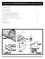
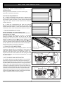
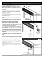
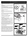
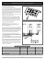
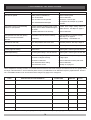
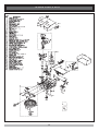
Easylifter ™
ROLLING GARAGE DOOR OPENER
OWNERS COPY
Installation Instructions
Warning: It is vital for the safety of persons to
follow all instructions. Failure to comply with the
installation instructions and the safety warnings
may result in serious personal injury and/or
property and remote control opener damage.
Please save these instructions for future reference.
IMPORTANT SAFETY INSTRUCTIONS
Warning - It is vital for the safety of persons to follow all instructions. Failure to comply
with the following Safety Rules may result in serious personal injury and/or property damage.
For ADDITIONAL SAFETY protection we
STRONGLY recommend the fitting of a Photo Electric
Beam. In most countries Photo Electric Beams are
mandatory on all garage doors fitted with automatic
openers. For a small additional outlay B&D recommends
that Photo Electric Beams be installed with the
automatic opener ensuring additional safety and peace
of mind.
DO NOT operate the garage door opener unless the
garage door is in full view and free from objects such as
cars and children/persons. SERIOUS PERSONAL
INJURY and/or property damage can result from failure
to follow this warning.
DO NOT operate the garage door opener when
children/persons are near the door. Children must be
supervised near the garage door at all times when the
door opener is in use. SERIOUS PERSONAL
INJURY and/or property damage can result from failure
to follow this warning.
DO NOT allow children to operate the garage door
opener. SERIOUS PERSONAL INJURY and/or
property damage can result from failure to follow this
warning.
Regularly check to make sure that the SAFETY
OBSTRUCTION FORCE is working correctly, and is
TESTED (by placing a 40mm high object on the floor)
and set as per the installation instruction manual. Failure
to follow the manual may result in SERIOUS
PERSONAL INJURY and/or property damage. This
test must be repeated at regular intervals and the
necessary adjustments made as required.
DO NOT disengage the door opener to manual
operation with children/persons or any other objects
including motor vehicles within the doorway.
Install the wall switch or wall mounted transmitter in a
LOCATION/POSITION where it is out of reach of
children and the garage door is visible.
The door opener is not intended for use by young
children or infirm persons without adequate supervision.
Young children should be supervised to ensure that they
do not play with the equipment.
The unit should be installed so that it is protected from
the elements. It should not be exposed to water or rain.
It is not to be immersed in water or sprayed directly by
a hose or other water carrying device.
The garage door must be WELL BALANCED.
Sticking or binding doors must be repaired by a
qualified garage door installer prior to installation of the
opener .
Frequently examine the installation, in particular
cables, springs and mountings. DO NOT attempt to
repair the door yourself as hardware is under extreme
tension and can cause SERIOUS PERSONAL
INJURY and/or property damage.
REMOVE OR DISENGAGE all garage doors locks
and mechanisms prior to installation of the opener.
Connect the garage door opener to a properly
EARTHED general purpose 240V mains power outlet
installed by a qualified electrical contractor.
DISCONNECT THE POWER CORD from mains
power before making any repairs or removing covers.
Only EXPERIENCED service personnel should
remove covers from the garage door opener.
When using auto close mode, a PHOTO ELECTRIC
BEAM must be fitted correctly and tested for operation
at regular intervals. EXTREME CAUTION is
recommended when using auto close mode. ALL
SAFETY RULES must be followed.
In order for the garage door opener to SENSE an object
obstructing the door way, some FORCE must be
exerted on the object. As a result the object, door and/or
person may suffer DAMAGE or INJURY.
If the power supply cord is damaged, it MUST be
replaced by an B&D service agent or suitably qualified
person.
Make sure that the door is fully open before driving in
or out of the garage.
Make sure the door is fully closed before leaving the
driveway.
Keep hands and loose clothing CLEAR of the garage
door and opener at all times.
B&D Doors & Openers Pty Ltd (B&D) to the extent that such may be lawfully excluded hereby expressly disclaims all conditions or warranties, statutory
or otherwise which may be implied by laws as conditions or warranties of purchase of a B&D Rolling Garage Door Opener. B&D hereby further
expressly excludes all or any liability for any injury, damage, cost, expense or claim whatsoever suffered by any person as a result whether directly
or indirectly from failure to install the B&D Rolling Garage Door Opener in accordance with these installation instructions.
3
FEATURES
Your Easylifter Auomatic Rolling Garage
Door Opener has many features which
you will appreciate. The components
and materials used in this Automatic
Opener are of the latest technology and
highest quality. Listed below are some
of the many features.
SECURITY CODE STORE
The Easylifter Garage Door Opener
uses state of the art technology in
storing your selected transmitter
security code. Up to 8
transmitters can be stored in the openers
memory.
OPERATION
To open or close the door simply press
the hand held transmitter, the wall
mounted transmitter, or optional wall
switch for two seconds. During an open
cycle the door can be stopped by
pressing the button while the door is in
motion. If it is interrupted during a close
cycle the door will pause
then
return to the fully open position. The
next actuation will move the door in the
opposite direction.
To store any code simply press and hold
the Door Code button on the opener and
press the transmitter button twice. Each
or all codes can be deleted and changed
at any time.
FIXED CODE
With only one of a possible 3.486 billion
able to open your door, you can rest safe in
the knowledge that only your remote will
allow access to the biggest opening to
your home.
ISS (INTELLIGENT SAFETY
OBSTRUCTION SYSTEM)
The door will automatically reverse
should it encounter an obstacle or be
restricted in some manner while
performing a close cycle. The amount
of force the door should sense before
reversing is automatically adjusted by
the door’s control system during the
initial installation of the automatic door
opener. The door will also stop if
restricted whilst opening. The Safety
Obstruction Force should be checked at
least once a month.
SERVICE INDICATOR
The opener features a service indicator.
When the Overload LED
and
the beeper sounds at the start of a door
cycle, this means that the opener and/or
garage door requires service.
CAS (COLOUR ASSISTED
SETTINGS)
To make the installation of the opener
simpler, B&D has developed the
CAS (Colour Assisted Settings) system.
This unique colour coded system (red
for close, green for open) allows for all
the adjustments and settings to be
easier and simpler for the user or
installer to complete the installation
OPEN AND CLOSE DRIVE
BUTTONS
Developed by B&D to aid with the
installation of the opener is the Open
and Close Drive Buttons. These buttons
are used to help set the open and close
limit positions. A quicker setting time
and a more precise limit position can be
achieved by using this system.
INITIALISATION
The Reset button on the opener is used
to initialise or re-initialise the
obstruction force settings and door
travel counters. See installation manual
for instructions.
AUTO CLOSE MODE
The opener can be programmed to
automatically close after an open cycle.
The auto close time is adjustable. It is
compulsory to install a Photo Electric
Beam if this mode is selected, otherwise
the door may cause personal injury or
damage to property.
SAFETY AUTO RUN TIME
If the opener does not complete its cycle
within thirty seconds it will
automatically stop if opening, or
reverse to the fully open position if
closing.
PHOTO ELECTRIC BEAM
(OPTIONAL)
The opener has an input for a photo
electric beam to be connected for extra
safety protection and use of the auto
close mode.
MANUAL OPERATION
The opener is equipped with a unique
patented manual disengaging device. If
the power to the opener is disrupted for
any reason the door can be put into
manual mode by pulling down on the
string handle, then releasing. This will
allow you to manually open or close the
door. When power is restored, by
pulling down on the string handle and
releasing, the opener is put back into
automatic mode.
4
OPERATING CONTROLS
1. LIGHT CODE button (White) is
used for storing or erasing the
transmitter button (code) you wish to
use to turn the opener’s courtesy light
on and off.
7. O/S/C button (Yellow) is used
during installation to test the Open, Stop
and Close cycles for the Opener. The
opener has to be initialised by the Reset
button before the O/S/C button becomes
operable.
2. DOOR CODE button (Blue) is
used for storing or erasing the
8. CLOSE LIMIT ADJUST
transmitter button (code) you wish to
SCREW (Red) is used to fine adjust the
use to command the door to open, stop close limit stop position.
or close.
9. OPEN LIMIT ADJUST SCREW
3. CLOSE DRIVE button (Red) is
(Green) is used to fine adjust the open
used during installation to help set the limit stop position.
close limit stop position. Pressing this
button will move the door in the close
10. OPEN LIMIT CAM (Green) is
direction. Movement stops when the used to set the open limit stop position.
button is released.
NOTE: The close safety obstruction
11. OPEN Drive button (Green) is
detection is disabled when the Close used during installation to help set the
Drive button is used to move the door.
open limit stop position. Pressing this
button will move the door in the open
4. CLOSE LIMIT LED (Red) the
direction. Movement stops when the
LED is very helpful during installation,
button is released.
it illuminates and flashes while the door NOTE: The open safety obstruction
is closing and remains steady on when detection is disabled when the Open
the close limit is reached.
Drive button is used to move the door.
5. AUTO CLOSE TIME button
(White) is used to adjust the auto close
time. While holding Auto Close and
pressing the Open button the time delay
is increased (each press will increase
the time by 5 seconds). Pressing the
Close button will decrease the time
delay.
12. OPEN LIMIT LED (Green) the
LED is very helpful during installation.
It illuminates and flashes while the door
is opening and remains steady on when
the open limit is reached.
6. RESET button is used to initialise
and set the door/opener operating
parameters, including cycle times and
obstruction force settings.
14. FORCE MARGIN SET button
(White) is used to change the force
pressure when the door encounters an
obstruction. Pressing the Force Margin
Set button and Open or Close button
will increase or decrease the force.
Normally the force pressure is set
automatically. Force Margin Set is
only used if other environmental factors
(wind, etc.) effect the operation of the
Door/Opener.
13. CLOSE LIMIT CAM (Red) is
used to set the close limit stop position.
5
15. P.E. INPUT is for connection of
Photo Electric Beams (optional extra)
for extra safety obstruction protection,
or compulsory when used with Auto
Close mode.
NOTE: P.E. SHUNT must not be
removed otherwise the opener will not
function correctly. Remove only when a
P.E. Beam is to be connected.
16. EXTERNAL RECEIVER
INPUT is the input where an external
receiver can be connected (optional
extra). It can supply 30mA @ 24 volts
DC maximum to power an external
receiver.
17. O/S/C INPUT is for connecting
the wired Wall Switch (optional extra) .
18. P. E. SHUNT The shunt has to be
removed when connecting a Photo
Electric Beam.
19. ENGAGE/DISENGAGEMENT
HANDLE when pulled down and
released will select manual mode on the
opener when there is a power failure.
Pulling down and releasing again will
switch the opener to automatic mode.
OPERATING CONTROLS
1)
2)
3)
4)
5)
6)
7)
8)
9)
10)
11)
12)
13)
14)
15)
16)
17)
18)
LIGHT CODE BUTTON (WHITE)
DOOR CODE BUTTON (BLUE)
CLOSE DRIVE BUTTON (RED)
CLOSE LIMIT LED (RED)
AUTO CLOSE BUTTON (WHITE)
RESET BUTTON
O/S/C BUTTON (YELLOW)
CLOSE LIMIT ADJUST SCREW (RED)
OPEN LIMIT ADJUST SCREW (GREEN)
OPEN LIMIT CAM (GREEN)
6
OPEN DRIVE BUTTON (GREEN)
OPEN LIMIT (RED)
CLOSE LIMIT CAM (RED)
FORCE MARGIN SET BUTTON
P.E. INPUT
EXTERNAL RECEIVER INPUT
O/S/C INPUT
P.E SHUNT
PACKAGE CONTENTS
ITEM
QUANTITY
EASYLIFTER DRIVE UNIT
1
HAND HELD TRANSMITTER
1
ALKALINE BATTERY A23 12V
1
WEIGHT BARS (NOT INCLUDED IN SOME MODELS)
2
SCREW M5x40mm (NOT INCLUDED IN SOME MODELS)
4
HEX NUT M5 (NOT INCLUDED IN SOME MODELS)
4
SPRING WASHER I.D 5 (NOT INCLUDED IN SOME MODELS)
4
SCREW #6x1”
2
PLASTIC WALL PLUGS
2
INSTALLATION MANUAL
1
7
BEFORE INSTALLATION
IMPORTANT SAFETY INSTRUCTIONS FOR
INSTALLATION
MINIMUM SIDE ROOM
FIG. 1
RECOMMENDED SIDE ROOM
FIG. 2
Warning: Incorrect installation can lead to severe injury.
Follow ALL installation instructions.
SIDE ROOM REQUIREMENTS
Fig. 1 shows the minimum side room that is required. The
distance between the edge of the door curtain and the inside of
the bracket is 85mm minimum, and the distance between the
edge of the door curtain and the outside of the bracket is
135mm minimum.
Fig. 2 shows the recommended side room. The distance
between the edge of the door curtain and the inside of the
bracket should be 110mm , and the distance between the edge
of the door curtain and the outside of the bracket is 160mm.
1. CHECK OPERATION OF DOOR
BEFORE BEGINNING THE INSTALLATION OF THE
EASYLIFTER AUTOMATIC GARAGE DOOR OPENER CHECK THE
OPERATION OF THE DOOR.
The door must be well balanced and be in a reasonable
operating condition. You should be able to lift the door
smoothly and with little resistance. It should stay open around
900mm to 1200mm above the
r. The door should not stick
or bind in the guide tracks. The ideal operational e ort in
raising or lowering the door should not exceed a force of 10kg
(22 lbs.). Make sure that all door locks are either removed, or
disabled and remove unnecessary accessories.
FIG. 3
2. FIXING OF DOOR WEIGHT BARS
Move the door manually to the mid open position. Place the
weight bars equally apart on the bottom rail of the door and
secure them with the fasteners provided(Fig. 3). Check the
operation of the door again. If the door feels heavy it may
require extra tension to be added to the door springs. Refer to
the door Installation manual from the manufacturer on how to
tension the door.
WEIGHT BARS
FIG. 4
3. LEFT OR RIGHT HAND INSTALLATION
The Easylifter Automatic Garage Door Opener can be installed
on the left or right hand side of the door (when looking out
from the inside of the garage). If the opener is to be installed on
the RIGHT HAND side of the door, then no change needs to be
made, as this is the standard factory setup. If LEFT HAND side
installation is required, the next step is to move the motor wire
connector on the control board. The connector plug has to be
removed and reconnected to the LEFT side of the connector
(Fig.4). If you have made an error in the selection and wish to
install on the RIGHT HAND side, then reconnect the connector
plug on the RIGHT side of the connector (Fig.5)
Connect the middle and left
hand side pins for left
hand side installation.
FIG. 5
Connect the middle and
right hand side pins for
right hand side installation.
8
MOUNTING THE OPENER
4. FIXING DRIVE UNIT TO THE DOOR
CHECK IF “U”
BOLT IS TIGHT
The Easylifter Drive Assembly can be fixed to the rolling
garage door in a variety of ways. Described below is one
method of fixing. Make sure there is enough side room (135mm
from the end of the door shaft to the wall) to slide the drive unit
onto the shaft.
PLEASE NOTE: THE INSTRUCTIONS FOR FIXING THE DRIVE
ASSEMBLY TO THE DOOR IS FOR RIGHT HAND INSTALLATION.
FIG. 10
FITTING DRIVE UNIT TO DOOR
(Fig. 10, Fig. 11 and Fig. 12).
ROPE
1. Check that the door shaft U bolt is securely tightened on the
left hand side of the door.
REMOVE “U” BOLT
REMOVE BRACKET
2. Raise the door and tie a rope around the centre to secure
the roll.
SUPPORT PROP
3. Support the right hand end of the door with a suitable prop,
e.g. step ladder and soft padding to protect the door surface.
WARNING: DO NOT ALLOW CHILDREN/PERSONS
AROUND THE DOOR AND PROP. SERIOUS PERSONAL
INJURY AND/OR PROPERTY DAMAGE CAN RESULT
FROM FAILURE TO FOLLOW THIS WARNING.
FIG. 11
4. Check that Steps 2 and 3 was completed. Carefully loosen
and remove the right hand door shaft U bolt.
5. Make sure that the door supporting prop is secure. While the
door is supported remove the right hand door mounting
bracket from wall.
6. Remove the drive unit from the packaging. Try to rotate the
drive gear by pushing on the fork. If the gear does not rotate
manual mode has to be selected. To select pull down on the
string handle, then release slowly. The drive gear should now
rotate freely.
7. Slide the drive unit over the door axle making sure that the
fork extends into and over one of the spokes of the door drum
wheel.
8. Refit the door mounting bracket to the wall. In some cases
the bracket may have to be re-positioned. Re-tighten the door
shaft U bolt. Remove door supporting prop and untie the rope
from the curtain.
9. Straighten the drive unit and position as per Fig. 12. Tighten
the two locking bolts firmly to secure the drive unit.
FIG. 12
10. Check the manual operation of the door by raising and
lowering the door. The door should run smoothly and not catch
on any part of the drive unit.
11. Adjust the length of the manual release cord so that it can
be easily reached by an adult of average height (ie. less than
1.8m tall).
TIGHTEN LOCKING BOLTS
TIGHTEN “U” BOLT
UNTIE ROPE
REMOVE PROP
9
REFIT WALL BRACKET
SETTING LIMITS
5. FIXING OF DOOR CURTAIN TO DRUM
WHEEL
The door curtain has to be secured to the drum wheel with
suitable fasteners.
1. With the door in the fully closed position, mark the curtain
(Fig. 13) on both ends of the door.
2. Open door slightly to have access to the marked positions.
Secure the curtain to drum wheel using self drilling screws (two
on each end). The screws should be at least 90 degrees apart
(Fig. 13).
FIG. 13
90
°
DRUM WHEEL
6. SETTING DOOR TRAVEL LIMIT
POSITIONS
IMPORTANT NOTE: The O/S/C button will not function
until the open and close limits positions are set and Step 7.1
is completed.
FIG. 14
The Limit Cams, Limit Fine Adjustment Screws and Door Inch
Open and Close buttons are colour coded to make the setting of
the limits as user friendly as possible.
The GREEN colours for OPEN LIMIT SETTING.
The RED colours for CLOSE LIMIT SETTING.
6.1 SETTING LIMITS FOR RIGHT HAND
INSTALLATION
1. With the drive unit in manual mode (Fig. 14) move the door
up by hand to the desired open position.
2. Remove the light diffuser (Fig. 14). Rotate the green limit
cam by hand in an anticlockwise direction (Fig. 15) until the
cam clicks the open limit switch.
3. Move the door down by hand to the desired closed position.
4. Rotate the red limit cam by hand in a clockwise direction
(Fig. 16) until the cam clicks the close limit switch.
5. Connect the power lead from the drive unit into, a general
purpose power outlet installed by a licensed electrical
contractor. Make sure that the power lead is safely fastened
away from any moving parts.Turn the power on.
6. Re-engage the drive gear by pulling down on the string and
then releasing slowly (Fig. 14).
OPEN LIMIT ADJUSTMENT
Press and hold the green Open button (Fig. 15) The door should
start opening. Release the green Open button when the door
reaches the desired open position. If the green LED (Fig. 15)
illuminated and the desired limit position has been reached then
the limit adjustment is complete. If the green LED is
illuminated but you are not happy with the door’s open
position, the green Fine Adjustment Screw (Fig. 15) can be
adjusted to fine tune the open position. Turn the screw anticlockwise to open the door more. To open the door less turn the
screw clockwise. Each complete revolution of the adjustment
screw is equal to approximately 10mm of door travel.
PRESS HERE
(BOTH SIDES)
AND PULL DOWN
TO REMOVE THE
LIGHT DIFFUSER
FIG. 15
is
10
SETTING LIMITS
NOTE: If the door has not reached the desired limit position by
more then 30mm, then it is recommended that the green limits
cam be adjusted again before the green fine adjustment screw is
adjusted.
FIG. 16
CLOSE LIMIT ADJUSTMENT
Press in and hold the red Close button .(Fig. 16). The door
should start closing. Release the red Close button when the
door reaches the desired closed position. If the red LED
(Fig. 16) is illuminated and the desired limit position has been
reached then the limit adjustment is complete. If the red LED is
illuminated but you are not happy with the door close position,
the red Fine Adjustment Screw (Fig. 16) can be adjusted to fine
tune the close position. Adjust the screw anticlockwise to close
the door less. To close the door more adjust the red Fine
Adjustment Screw clockwise. Each complete revolution of the
adjustment screw is equal to approximately 10 mm of door
travel.
NOTE: If the door has not reached the desired limit position
by more then 30mm, then it is recommended that the red
limits cam be adjusted again before the red fine adjustment
screw is turned.
6.2 SETTING LIMITS FOR LEFT HAND
INSTALLATION
1. With the drive unit in manual mode (Fig. 17) move the door
up by hand to the desired open position.
2. Remove the light diffuser (Fig. 17) . Rotate the green limit
cam by hand in a clockwise direction(Fig. 18) until the cam
clicks the open limit switch.
3. Move the door down by hand to the desired closed position.
4. Rotate the red limit cam by hand in an anticlockwise
direction (Fig. 19) until the cam clicks the close limit switch.
5. Connect the power lead from the drive unit into a general
purpose power outlet installed by a licensed qualified
electrical contractor. Make sure that the power lead is safely
fastened away from any moving parts. Turn the power on.
6. Re-engage the drive gear by pulling down on the string
and then releasing slowly (Fig. 17) .
11
FIG. 17
PRESS HERE
(BOTH SIDES)
AND PULL DOWN
TO REMOVE THE
LIGHT DIFFUSER
SETTING LIMITS
OPEN LIMIT ADJUSTMENT
Press and hold the green Open button (Fig. 18). The door
should start opening. Release the Open button when the door
reaches the desired open limit stop position. If the green LED
(Fig. 18) is illuminated and the desired limit stop position has
been reached then the limit adjustment is complete. If the green
LED is illuminated but you are not happy with the door open
position, the green Fine Adjustment Screw (Fig. 18) can be
adjusted to fine tune the open position. To open the door more,
turn the Green Fine Adjustment Screw clockwise. To open the
door less turn the Green Fine Adjustment screw anticlockwise.
Each complete revolution of the adjustment screw is equal to
approximately 10mm of door travel.
FIG. 18
NOTE: If the door has not reached the desired limit position
by more then 30mm, it is recommended that the green limit cam
be adjusted again before the green fine adjustment screw is
turned.
CLOSE LIMIT ADJUSTMENT
Press and hold the red Close button (Fig. 19). The door should
start closing. Release the Close button when the door reaches
the desired closed limit stop position. If the red LED (Fig. 19)
is illuminated and the desired limit position has been reached
then the limit adjustment is complete. If the red LED is
illuminated but you are not happy with the door close position,
the red Fine Adjustment Screw (Fig. 19) can be adjusted to fine
tune the close position. Turn the screw clockwise to close the
door less. To close the door more turn the screw anticlockwise.
Each complete revolution of the adjustment screw is equal to
approximately 10mm of door travel.
FIG. 19
NOTE: If the door has not reached the desired limit position
by more then 30mm, then it is recommended that the red limit
cam be adjusted again before the red fine adjustment screw is
turned.
12
SETTING SAFETY OBSTRUCTION FORCE
7. SETTING OPEN AND CLOSE SAFETY
OBSTRUCTION FORCE
The Safety Obstruction Force is calculated automatically and
set in memory on the Easylifter. This applies to both the Open
Force and Close Force.
FIG. 20
Warning: When step 7.1 is initiated the garage door will do a
full open and close cycle automatically. Please keep doorway
clear to avoid any personal injury or damage to property.
7.1 TO INITIALISE OBSTRUCTION FORCE
1. Press and hold the Close button (Fig. 20) to move the door
to the fully closed position. Check that the red LED is steady
ON, to confirm the door is set on the closed limit position
2. Press the Reset button (Fig. 20) for two seconds, the door
should start opening. When the door reaches the fully open
position it will pause momentarily then start to close. The door
has to do a complete open and close cycle without
interruptions for the safety obstruction parameters to be
calculated and set automatically.
FIG. 21
A default safety force margin is preset in the factory. Under
normal operating conditions this default margin should not be
changed. If you are not satisfied with this setting you can adjust
it as per the procedure below.
IMPORTANT NOTE:
Whenever the limit switches or cams are adjusted the safety
obstruction force has to be re-initialised because the door’s
travel distance may have changed. To re-initialise the door
follow STEP 7.1 above.
7.2 TO INCREASE FORCE PRESSURE
1. Press and hold the Force Margin Set button (Fig. 20).
2. While holding Force Margin Set press the green Open
button. The green LED will illuminate each time the green open
button is pressed to indicate that the force pressure is being
increased. If the green LED flashes continuously when the open
button is pressed, this indicates that the maximum force
pressure setting has been reached.
7.3 TO DECREASE FORCE PRESSURE
1. Press and hold the Force Margin Set button (Fig. 20).
2. While holding down button press the red Close button. The
red LED will illuminate each time the Close button is pressed,
to indicate that the force pressure is being reduced. If the red
LED flashes continuously when the close button is pressed, this
indicates that the minimum force pressure setting has been
reached.
7.4 TO RECALL FACTORY SET FORCE
1. While holding the Force Margin Set button press the RESET
button for two seconds.
2. Release both buttons. The default setting should now
be recalled
WOOD (40mm High)
7.4 SAFETY OBSTRUCTION TEST
TESTING CLOSE CYCLE
1. Open the door by pressing the Yellow O/S/C button (Fig. 20).
2. Place a length of timber 40mm high on the floor directly under
the door (Fig. 21).
3. Press the Yellow O/S/C button to close door. The door should
strike the object and start to re-open.
TESTING OPEN CYCLE
1. Close the door by pressing the Yellow O/S/C button. (Fig. 20).
2. Press again to open the door. When the door opens half way
grab the bottom rail of the door firmly, the door should stop.
If the door does not reverse readily when closing, or stop when
opening, the force may be excessive and need adjusting, refer to
STEP 7.1, 7.2, 7.3 and 7.4.
IMPORTANT WARNING: If the door is closing and is unable to
re-open when obstructed discontinue use. Do not use a door with
faulty obstruction sensing. Repair fault and re-test before using.
13
CODING TRANSMITTERS
8. STORING TRANSMITTER CODES
Make sure to connect the battery to the transmitters. The
memory in the openers receiver can store up to
remote control transmitters buttons.
FIG. 22
PRESS AND
HOLD DOOR
CODE
BUTTON
8.1 STORING TRANSMITTER CODE
1. Press the DOOR CODE button on the Easylifter opener. The
Door Code LED will illuminate to indicate that learn
mode is activated. If a valid code is not stored in 15 seconds
the Easylifter opener will exit learn mode.
2. SMART CODE TRANSMITTERS ONLY - Press and hold the
transmitter button to be programmed until the DOOR
PRESS THE BUTTON
FOR TWO SECONDS
DIP SWITCH TRANSMITTERS ONLY - Select your dip switch
press and hold the remote control transmitter button to
3. Release the button on the transmitter - the code is now set.
4. Press the transmitter button to test if it operates the door.
14
CODING TRANSMITTERS
11. SETTING THE TRANSMITTER TO OPERATE THE
COURTESY LIGHT
FIG. 25
Although the courtesy light comes on with each operation of
the opener, the courtesy light may also be controlled by a
remote control transmitter without operating the door. To code
one of the remote control transmitter buttons to turn the
courtesy light on and off:
1 - Press the Light Code button on the opener. The Light Code
LED will illuminate and courtesy light will turn on to show
that you are learning the code for controlling the courtesy
light.
2 - Choose a button on the transmitter not already coded to
operate the door and press until the Light Code LED
flashes.
3 - Press the transmitter button to test if it switches on the light.
12. ADJUSTING COURTESY LIGHT TIME
The preset courtesy light time on the Door Opener is 3 minutes.
This time can be changed as below.
1. Press and hold the Auto Close Time and Force Margin Set
buttons together (Fig. 26)
.
2. While holding the two buttons, press the green Open
button (Fig. 26). Each press will add 10 seconds to the light
time.
3. To decrease the time follow step 1 and press the red Close
button (Fig. 26). Each press will deduct 10 seconds from the
light time.
4. To recall the factory set default light time press and hold the
Auto Close Time, Force Margin Set and Reset buttons
together for about 2 seconds. (Fig. 26)
.
FIG. 26
13. DELETING PROGRAMMED CODES
13.1 Delete all transmitters codes from the operate channel
1. Press and hold the Door Code button for approximately six
seconds
2. The Door Code LED will blink for one second to indicate all
codes have been erased
3. Press the transmitter button to ensure it does NOT operate
the door
FIG. 27
13.1 Delete all transmitters codes from the courtesy light
channel
1. Press and hold the Light Code button for approximately six
seconds
2. The Light Code LED will blink for one second to indicate all
codes have been erased
3. Press the transmitter button to ensure it does NOT operate
the courtesy light
15
PE BEAM AND AUTO CLOSE
14. FITTING THE SAFETY PHOTO
FIG. 28
ELECTRIC BEAM SENSOR (OPTIONAL)
Locate the Photo Electric Beam (P.E.) normally closed contact
type in a strategic location within doorway. We recommend
150mm above the floor level and as close as possible to the
door opening, inside the garage. Remove shunt from P.E
connector (Fig. 28) and connect the plug from the P.E. wiring
harness to P.E. connector (Fig. 29). The wiring diagram is for
Model PHBE (Order Code 062153).
Make sure to align the beams correctly. Follow the manual
supplied with the Photo Electric Beam.
WARNING; When using Auto Close Mode and P.E. Beams,
the doorway must be clear of all obstructions and persons
at all times. The location of the beam and manner in which
it is installed might not give safety protection at all times.
Check to make sure that the height of the beam and type
used give maximum protection possible.
FIG. 29
15. SETTING AUTO CLOSE TIME
IMPORTANT NOTICE: IT IS COMPULSORY TO
INSTALL A PHOTO ELECTRIC BEAM BEFORE USING
THE AUTO CLOSE MODE.
The Auto Close timer will only start after the Photo Electric
Beams (P.E.) path is broken and the auto close time has been
set. If the P.E. path is not broken the door will remain open until
the path is broken. If the door opener incurs an obstruction (not
from the P.E.) while closing the door will re-open and not auto
close until the path of the P.E. beam is broken again.
1. Press and hold the Auto Close Time button (Fig. 28).
2. While holding the Auto Close Time button, press the Open
button (Fig. 28). Each press of this button will add five seconds
to the auto close delay time.
3. To decrease the delay time follow Step 1 and press the Close
button. Each press will deduct five seconds from the auto close
time.
4. Press the O/S/C button (Fig. 28) or transmitter to open the
door. When the door is fully opened the Open Limit green LED
will flash to indicate that the auto close mode is in operation.
5. Break the path of the P.E. Beam momentarily, this will
initialise the auto close mode. The door will close once the set
auto close time has elapsed.
FACTORY DEFAULT SETTINGS
DEFAULT
STEP
MAXIMUM
MAXIMUM MOTOR RUN TIME
30 Secs.
—
—
COURTESY LIGHT TIME
3 Mins.
10 Secs.
10 Mins.
10
1
20
0 Secs.
5 Secs.
4 Mins.
OBSTRUCTION FORCE MARGIN
AUTO CLOSE TIME
16
PARAMETERS & SPECIFICATIONS
DOOR STATUS INDICATORS
OPEN LED
GREEN
DOOR OPENER STATE
OPEN
CLOSE LED
RED
DOOR STATUS
LED YELLOW
BEEPER
ON
ON
CLOSE
FLASHING
OPENING
FLASHING
CLOSING
DOOR TRAVEL STOPPED
FLASHING
DOOR OBSTRUCTED WHEN OPENING
FLASHING
FLASHING
DOOR OBSTRUCTED WHEN CLOSING
FLASHING
DOOR OVERLOADED
ALTERNATING
FLASHES
DOOR IN OPEN POSITION WITH
AUTO CLOSE MODE SELECTED
ONE SECOND
FLASHES
MAINS POWER INTERRUPTED
BEEPS WHILE
DOOR IS MOVING
ALTERNATING
FLASHES
RAPID
FLASHES
TECHNICAL SPECIFICATIONS
INPUT VOLTAGE:
TRANSFORMER PRIMARY VOLTAGE:
SECONDARY VOLTAGE:
CONTROLLER VOLTAGE:
1,2
WIDTH:
MAXIMUM DOOR OPENING:
HEIGHT:
RATED LOAD:
OPENER OPENING/CLOSING LIMITS TRAVEL:
OPENER MAXIMUM
OPENING/CLOSING RUN TIME:
RECEIVER TYPE:
RECEIVER CODE STORAGE CAPACITY:
TRANSMITTER FREQUENCY:
CODING TYPE:
No. of CODE COMBINATIONS:
PTX-4 TRANSMITTER BATTERY:
EAT-1 TRANSMITTER BATTERY:
MOTOR TYPE:
MOTOR VOLTAGE:
GLOBE:
230V- 240V AC 50Hz
(Other voltages available upon request
e.g. 110V AC 60Hz)
230V / 240VAC
24V AC 100 VA
24V DC
5100mm
3100mm
200N
3.5 Turns of Door Drum Wheel
30 Secs.
UHF 433.92 MHz. AM Receiver
21 x Transmitter Button Codes (shared between door operate and courtesy light)
433.92 MHz
Fixed Code
Over 3.486 B illion Random Codes
A23 Alkaline 12 Volts
CR1220 Lithium 3 Volts
Permanent Magnet Direct Current
24V DC
Festoon Type - 15w 24V DC
Note:
1. The maximum Roll ing Door (Domestic) opening that the Easylifter can be installed on is 5100mm wide by 3100mm high
. The
door must be well balanced. A person should be able to lift the door up manually with very little e ort in case of an emergency
.
2. Intermittent operations may occur in areas which experience very strong winds. The strong wind puts extra pressure on the
oord
and tracks which may in turn trigger the safety obstruction detection system intermittently.
17
TROUBLE SHOOTING
SYMPTOM
POSSIBLE CAUSE
Door will not operate.
REMEDY
Mains power not switched on.
Switch on mains power.
Door is obstructed.
Remove obstruction.
Door is locked or motor jammed.
Unlock door or remove jam.
Door tracks/hardware damaged.
Door requires service/repair by qualified
technician.
Door starts to close but automatically
reverses to open position.
Adverse weather conditions (wind or cold) Increase force margin setting and/or recausing door to stiffen and become tight in initialise the door . See Step 8 on page 11.
the tracks.
Remove obstruction.
Possible obstruction in the doorway.
Door operates from drive unit (O/S/C)
Transmitter code not stored in memory.
Code transmitter in to openers memory.
Refer Step 8.1 on page 14.
Flat Battery.
Replace battery - A23 Alkaline 12V.
Door will not close fully.
Door limit positions need to be reset.
Reset limit positions. See Step 6 Page 10.
Door will not open fully.
Door limit positions need to be reset.
Reset limit positions. See Step 6 Page 10.
Courtesy light not working.
Globe blown.
Replace globe - festoon type 15W 24V DC.
Globe keeps blowing.
Incorrect globe voltage - must be 24V DC.
Replace globe - festoon type 15W 24V DC.
Auto close not working.
PE Beam or wiring faulty
Repair PE Beam or replace wiring.
PE Beam not aligned correctly.
Re-align optics.
PE Beam is obstructed.
Remove obstruction from the path of PE.
Door obstructed when closing.
Remove obstruction.
Auto close time not set.
See Step 15 on page 16.
button but not from transmitter.*
See note.
*Please Note: Some areas may be prone to excessive radio interference brought on by devices such as cordless telephones, wireless
stereo headphones and baby monitors. It is possible that these devices could cause a degree of interference such as to greatly reduce
the range of the transmitter. In such an instance please contact your B&D dealer for an alternative frequency replacement kit. As this is
not a warrantable situation but an environmental issue charges may apply for the changeover.
DATE
MAINTENANCE PERFORMED BY
SIGNATURE
AMOUNT
Please Note: Failure to maintain your garage door may void the warranty for your garage door opener.
18
INV. No.
SPARE PARTS LIST
19
WARRANTY
1.
Definitions
‘B&D’ means
(a) in Australia - B&D Doors of 17 Oasis Court, Clontarf, Queensland, 4019, a division of B&D Australia Pty Ltd
(ABN 25 010 473 971), or
(b) in New Zealand - B&D Doors NZ Ltd of 70 Allens Road East Tamaki Auckland, which is a subsidiary of B&D
Australia Pty Ltd.
‘Purchaser’ means the purchaser of the Opener.
‘Opener’ means the ‘Easylifter Automatic Garage Door Opener’
‘Authorised Distributor’ means an approved B&D distributor of the Opener.
‘Major Components’ means all components of the Opener that make up the power head that is attached to a garage
door.
‘Ancillary Components’ means all components of the Opener which are not Major Components.
‘Manufacturer’s Written Instruction Manual’ means the instruction manual provided with the Opener.
2.
This warranty applies to every sale of an Opener to a Purchaser by B&D or its approved distributor, and is the only
warranty given on behalf of B&D.
3.
B&D warrants that it will, at its option, either repair or replace any defects:
(i)
(ii)
in materials or workmanship in the Opener, subject to the following:
(a) for Major Components of the Opener that are installed by B&D or an approved distributor the warranty
shall be valid for a period of twelve (12) months;
(b) for Major Components of the Opener that are not installed by B&D or an approved distributor the
warranty shall be valid for a period of twelve (12) months, provided that all costs of disconnection,
reinstallation and freight shall be borne by the Purchaser.
for Ancillary Components of the Opener the warranty shall be valid for a period of twelve (12) months.
in installation for a period of twelve (12) months from the date of installation where the Opener has been
installed by B&D or its Authorised Distributor.
4.
The warranties provided in clause 3(i) shall only apply to an Opener which is being used under normal use
and service in accordance with the Manufacturer’s Written Instruction Manual and are limited to the repair or
replacement, at B&D’s option, of any defective Opener or parts thereof.
5.
The warranty provided in clause 3(i) shall apply from:
(i)
the date of delivery of the Opener by B&D; or
(ii)
the date of installation of the Opener by B&D or one of its authorised installers; or
(iii)
the date of purchase of the Opener by the Purchaser;
whichever is the later.
6.
(i)
(ii)
Where the Opener has been sold to the Purchaser by B&D, the Purchaser shall make all warranty claims
hereunder directly with B&D;
Where the Opener has been sold to the Purchaser by an Authorised Distributor, the Purchaser
shall make all warranty claims hereunder directly with the Authorised Distributor.
7.
The Purchaser will pay for any service call made by B&D or an Authorised Distributor where such a call is made for
the purpose of adjustment (as described in the Manufacturers Written Instruction Manual) and not for rectification
of a defect pursuant to the warranty hereunder.
8.
(i)
The Purchaser shall be responsible for any expense incurred by B&D or an Authorised Distributor in
ensuring that the Opener is readily accessible for any repair work carried out under this warranty.
Where an Opener is installed outside a capital city metropolitan area and a warranty claim is made pursuant to this
warranty, any travelling expenses and costs of transporting the Opener, incurred by B&D or its Authorised Distributor,
shall be borne by the Purchaser.
©Copyright 2006 B&D Doors
- 20 -
P/N: 05xxx
WARRANTY
9.
Subject to paragraph 12 hereof;
(i)
(ii)
10.
the obligations of B&D under this warranty are limited to those contained herein and such warranties are
expressly in lieu of all other warranties, express or implied, including any implied warranty of
merchantability or fitness for a particular purpose and notwithstanding any course of dealing between the
parties or custom and usage in the trade to the contrary.
B&D shall not be subject to nor incur and the Purchaser releases B&D from any claim or liability
(including consequential loss or damage and loss or use or profit) by reason of delay, defective or faulty
materials or workmanship, negligence or any act, matter or thing done, admitted or omitted by B&D.
Subject to Clause 12 hereof, this warranty does not extend to and B&D will be relieved of all obligations,
responsibilities and liabilities (direct or consequential) in the event that defects in manufacture of the Opener are
directly or indirectly in the opinion of B&D due to or result from:
(i)
(ii)
(iii)
(iv)
(v)
(vi)
(vii)
(viii)
(ix)
(x)
being fitted to any door or other closing device which is not of the type or condition defined in the
Manufacturers Written Instruction Manual as suitable for installation of the Opener.
Lack of proper maintenance or care – failure to have the door serviced annually may void this warranty.
Incorrect and unreasonable use.
Faulty installation or adjustment of the Opener or door to which the Opener is connected where such
installation or adjustment is not carried out by B&D or one of its Authorised B&D Distributors.
Failure to observe any instructions or directions provided with the Opener or given to the Purchaser by
B&D or an Authorised Distributor.
Modifications or repairs made or attempted to be made by any unauthorised person.
Faulty electrical wiring of structures to which the Opener is affixed.
Radio (including citizen brand transmissions) or other electronic interference.
Water damage, including effects from rust and corrosion.
Use with doors locked.
11.
The warranty contained in Clause 3 does not cover batteries or globes and B&D shall not be liable for any defect,
malfunction or failure of such items.
12.
It is expressly provided that the warranties or any terms and conditions of them or other statement contained in
this document or other literature given to the Purchaser shall not be read or applied so as to purport to exclude,
restrict or modify or have the effect of excluding, restricting or modifying the application in relation to the supply
of the Opener of all or any of the provisions of Divisions 2 and 2A of Part V of the Trade Practices Act, 1974, or
the Consumer Guarantees Act 1993 if the purchase is a ‘consumer’ and purchased the opener in New Zealand,
(“The Act”) as amended or the exercise of a right conferred by such a provision or any other condition or warranty
implied by any relevant State Act or Territorial Ordinance or by the general law and which by law cannot be
excluded, restricted or modified provided that to the extent that the Act permits B&D to limit its liability for a breach
of condition or warranty implied by the Act, B&D’s liability for such breach shall be limited to the payment of the
cost of replacing the Opener or acquiring an equivalent Opener or repairing the Opener.
13.
This warranty shall be governed by and construed in accordance with Australian law if the opener was purchased
in Australia, or New Zealand law if the opener was purchased in New Zealand
14.
Upon making a claim under this warranty the purchaser must produce proof of the date of purchase, together with
the details set out below:
Purchased From: _______________________________________________
Installed By: __________________________________________________
Installed Date: _________________________________________________
The Purchaser shall complete this certificate and keep it together with a copy of the receipt of purchase in a safe place
– production of such information will assist the handling of a claim made under this warranty.
©Copyright 2006 B&D Doors
- 21 -
P/N: 05xxx
QLD Office:
17 Oasis Court, Clontarf 4019.
Ph: (07) 3883 0200
NSW Office:
34-36 Marigold St, Revesby 2212.
Ph: (02) 9722 5555
VIC/TAS Office:
147-153 Canterbury Road, Kilsyth 3137.
Ph: (03) 9237 7766
SA Office:
23 Frederick Road, Royal Park 5014.
Ph: (08) 8440 4747
WA Office:
96 Mulgul Drive, Malaga 6090.
Ph: (08) 9247 8777
NZ Office:
70 Allens Road, East Tamaki, Auckland.
www.bnd.co.nz
Ph: (09) 273 8600
B&D Doors is a Division of B&D Australia Pty Limited - ABN 25 010 473 971
www.bnd.com.au
©Copyright 2006 B&D Doors. All Rights Reserved. ® and ™ are registered trademarks of B&D Australia Pty Ltd. In an ongoing commitment to
product quality B&D Doors reserve the right to change specifications without notice. E&OE.


![Installation Manual [PDF 3.1 MB]](http://vs1.manualzilla.com/store/data/006000040_1-a740b84bcdd0f591a4a671097fdfa72a-150x150.png)