1
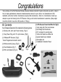
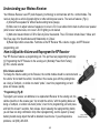
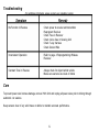
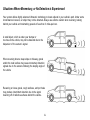
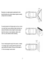
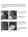
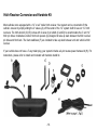
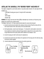
MODEL: ASH300
OBSTACLE SENSING SYSTEM
FOR
TRAILER HITCH MOUNTING
Owner/Installation Manual
IMPORTANT:
HITCHLOCK
KEY CODE
ATTENTION: “REFER TO YOUR KEYS FOR CODE”
YOUR KEY CODE IS:
CUSTOMER SERVICE (800) 225-6074
Place in owner’s glove box for future reference
-1-
Congratulations
Your purchase of the Hitch Mounted Wireless Reverse Obstacle Detection System will provide you with a state of
the art, highly sophisticated, ultrasonic obstacle detection device for your vehicle. It is manufactured to ISO
standards, and under normal circumstances requires little maintenance. Under no circumstances should you
attempt to open the Sensing Unit or RF Receiver. Doing so will void all manufacturer’s warranties. (Step weight
should be limited to less than 250 pounds or 110kgs.)
Kit Contents:
Your Obstacle Detection Kit contains the following items:
(1) Sensing Unit, with 2-pin Power harness, (Fig.A)
(1) 7way Power Plug, with 18” 2-pin harness. (Fig.B)
(1) *Wireless RF Receiver. (Fig.C)
Factor Programmed to match A and C
(1) HitchLock with (2) keys. (Fig.D)
(2) Foam Stabilizers (Fig. F)
(2) Hitch Lock Spacers (Fig. G)
Fig.G
(1) 2 Pin Reverse Power Hard Wire Kit: (Fig.E)
(1) 2-pin plug with 9 foot wire harness
(2) 22-18awg Red ScotchLock
(6) 8” tie straps for securing wires
(1) inline mini blade fuse holder 2A
(2) spare blade fuses included
(2) butt splice red
(1) Installation Instruction Sheet
Fig.D
Fig.E
Fig.C
Fig.F
Fig.A
Fig.B
-2-
Understanding your Obstacle Detection System’s functions
Your system sends and receives Ultrasonic Signals that are projected from sensors mounted in the Sensing Unit.
As the signals “echo” off of objects in the detection field, and return to the sensors, the systems’s microprocessor
exports them to its onboard, output signal transmitter. These signals are transmitted through Radio Frequency
Waves to the Chime Module located in the vehicle. The detection signals are then translated into audible warnings
for the driver.
Your system will detect and notify the driver with 3 distinct “Tones” (beeps), which correspond with your vehicle’s
distance to objects in the detection zone. Upon engaging into reverse gear, you should hear 1 distinct tone. This
serves multiple functions:
1) Notification that the system is active and is scanning for objects in the detection field.
2) As a reminder that you have selected the reverse gear.
3) As an indication that your system has performed a self check. If more than one “quick beep” occurs
your system may need to be checked. If warning tones continue after reverse gear is initially selected, check for
obstacles behind the vehicle. If nothing is behind the vehicle refer to the troubleshooting guide.
Overview of your detection Zones and Notifications
“Zone1” Slow beeps and Slow Green flashing LED from the
wireless receiver.
“Zone2” Rapid beeps and Rapid Yellow flashing LED from the
wireless receiver.
“Zone3” Solid tone and Solid Red LED from the wireless
Zone 3 Zone 2 Zone 1 receiver.
0-3 feet 3-5 feet 5-7 feet
Wireless RF Receiver:
(A) Speaker
(B) Volume/LED Slider
(C) Visual Indicator LED
(D) Volume & Reprogram
Control
-3-
Understanding your Wireless Receiver
Your Wireless Receiver uses RF (radio frequency) technology to communicate with the control module. This
receiver plugs into a vehicle Cigarette lighter or other similar power source. The receiver features: (Fig A)
A) Internal Piezo speaker for efficient audio warning tones (beeps).
B) Slide cover to to adjust volume of speaker or to cover L.E.D. Cover slides front to back to either cover speaker
ports to lower volume levels, or to cover L.E.D if lighting is not desired.
C) Multi-color visual indicator L.E.D for Zone by Zone Visual alerts. The L.E.D colors include Green, Yellow, and
Red. See page 3 for Specifications and Relationship to “Zones”.
D) Reset style button access hole. Functions as the RF Receiver Hi/Lo volume toggle, and RF Receiver
programming port.
How to Adjust the Volume and Reprogram the RF Receiver
Your RF Receiver features a programming port. This port has two programming functions:
(1) Programming the RF Receiver to the sensing unit. (Normally Preset from Factory)
(2) Hi/Lo volume selector.
Hi/Lo Volume selection:
To change the Volume setting on the Receiver, the control module should be connected and
the vehicle “do not start the vehicle,” should be in the reverse gear with the parking brake
set. Using a Toothpick, or similar non-metal “probe”, insert into programming port and
press and release quickly.
* Programming: (Fig.B)
To program your receiver, an additional, or a replacement Receiver to the sensing unit, the
vehicle should be in the reverse gear, “do not start the vehicle,” with the parking brake set.
Using a Toothpick, or similar non-metal ”probe”, insert it into programming port and press
and hold for at least 5 seconds, then release. Upon releasing the reprogramming button,
you will hear one long confirmation chirp. After reprogramming, test the system by slowly
backing toward a large object that will be detected in each zone. If you still experience
problems, call (800) 225-6074.
--4-
Troubleshooting
(For additional information, please contact your installation center.)
Symptom
Remedy
No Function in Reverse
Check power to receiver and transmitter
Reprogram Receiver
Check Fuse in Receiver
Check in-line fuse in Sensing Unit
Check 7-way harness
Check Ground Wire
Inconsistent Operation
Refer to page 4 Reprogramming Wireless
Receiver.
Constant Tone in Reverse
Always check for object behind vehicle
Make sure sensors are clean of debris
Care
To prevent power wire harness damage, remove Hitch Unit and unplug all power wires prior to driving through
automatic car washes.
Keep sensors clear of any solid mass or debris to maintain accurate performance.
-5-
Situations Where Momentary, or No Detection is Experienced
Your system utilizes highly advanced Ultrasonic technology to locate objects in your vehicle’s path. Under some
circumstances however, an object may not be detected. Always use extreme caution when reversing, looking
behind your vehicle and maintaining speeds of less than 3 miles-per-hour.
A small object, which is under your bumper or
too close to the vehicle, may not be detected due to the
dispersion of the sensor’s signal.
When reversing down a steep slope or driveway, gravel
and/or the road surface may cause momentary detection
signals due to the sensors following the sloping angle of
the vehicle
Reversing on loose gravel, rough surfaces, and pot holes
may produce intermittent detection due to the signal
bouncing off of reflective surfaces behind the vehicle.
-6-
Reversing at an angle towards a partial wall or other
large flat surface may refract ultrasonic signals, causing
an object not to be detected.
If reversing towards a 90 degree angle, such as a corner
of a wall or pillar, sensor detection pattern will refract as
shown until vehicle is close enough to receive signal
back from corners. In such situations, vehicle could
reach very close distances before detecting.
Due to natural projection angle of the sensors, a natural
“no coverage” area is common with the system at the
outer corners of the vehicle. This may occur at about 010” from the bumper’s outer corners.
-7-
Installation Guide
This Hitch-Mounted Wireless Reverse Obstacle Detection System is
for Trailer Hitch Heights Over 15” From Road Surface.
-8-
Your system can be installed with a few easy steps, providing your vehicle comes equipped with a 7-way
connector socket and a standard 2” Hitch Receiver. If your vehicle is not equipped with a 7-way connector, you
can obtain a power connection using the provided 2-pin reverse power hardwire kit and retreive power at the
reverse light harness.
You can begin by inserting the 7way plug
into the vehicle’s 7way socket, (Fig.A).
Insert the Sensing Unit into the Trailer
Hitch of the vehicle, (Fig.B).
Use the HitchLock to secure the
2” sleeve and the Sensing Unit into the
vehicle’s trailer hitch receiver, (Fig.C).
The RF Receiver will be plugged into the
vehicle’s cigarette lighter, or similar 12 volt
port. (Fig.D)
-9-
Hitch Receiver Conversion and Hardwire Kit
Most vehicles come equipped with a 1¼” or a 2” trailer hitch receiver. Your system can be converted to fit the
vehicle’s receiver by simply sliding the 2“ sleeve (A), off the center of the 1¼” system shaft for use on 1¼” hitch
receivers. The hitch-lock kit (C,D,E) comes with 2 sizes of pin shafts (C and D) to accommodate the 2” and 1¼”
hitch pin holes. Included are rubber hitch lock spacers (G) designed to take up slack between the hitch receiver
pin holes and hitch-lock. The foam stabilizers (F) are included to take up slack between unit and vehicle’s hitch
receiver.
If your vehicle does not have a 7-way trailer plug, your system includes a 2-pin reverse power harness kit (H). For
instructions, please refer to install card included with hardwire install kit.
-10-
INSTALLING THE UNIVERSAL 2 PIN “REVERSE POWER” HARD WIRE KIT
This adapter is designed for use with vehicles without a 7-way factory trailer connection. The tools required for this
installation are:
- 12Volt Meter for testing power (use of a Test Light is NOT recommended)
- Pliers
- Wire Crimpers
- Electrical Tape
WARNING: Do not plug 2 pin harness into factory (OEM) or aftermarket 4 pin connectors, and if used may cause
damage to the unit and void any implied warranty.
This adapter kit will use the +12V power supply normally located at the reverse bulb and ground.
1.) Connect the hard wire 2-pin connector to the sensing unit 2-pin connector. Route the harness from the
hitch receiver location into the vehicle and up to the reverse bulb location.
2.) Set the parking brake, Locate the wire that measures +12 volts when the vehicle ignition is turned on to
the run position (do not start the vehicle) and the gear selector is placed into the reverse position. Move
the gear selector back into the park position and the selected wire will measure 0 volts.
3.) Connect the orange wire from the inline fuse to the selected wire.
4.) Connect the red wire from the 2-pin harness to the opposite end of the orange wire of the inline fuse using
the red butt connector supplied.
5) Connect the black wire from the 2-pin harness to the vehicle’s ground wire.
-11-
The Universal 2-Pin Hardwire Kit is
For Use in Vehicles
NOT Equipped with a Factory
7-Way Connector
A. Reverse Bulb
B. Reverse 12Volt Wire
C. Reverse Ground Wire
D. Scotch Locks
E. Inline Fuse Holder
F. Butt Connector
G. 2 Pin Harness
H. “Red” Wire from supplied harness
I. “Black” Wire from supplied harness
-12-
Warranty & Limitations of Coverage
Congratulations on the purchase of your hitch mounted obstacle detection system. Your system is a highly
sophisticated, ultrasonic obstacle detection device. It is manufactured to exacting standards, and under normal
circumstances requires little maintenance. Under no circumstances should you attempt to open the sensing unit
or chime module. Doing so will void all manufacturer’s warranties.
Parts Policy
All products are warranted to the original owner for electrical component defects. Refer to your enclosed warranty
registration card for warranty details. Defective parts are exchanged on a part for part basis. No returns will be
accepted without an approved Return Authorization Number (R.A.#) from the company. Replacement parts will be
issued upon receipt of returned goods and following verification of defective status unless other arrangements are
approved. Whenever possible, return to your original selling dealer for warranty replacement or call:
(800) 225-6074 for assistance.
FCC Information
This device complies with Part 15 of the FCC Rules and Operation, and is subject to the following two conditions:
(1) This device may not cause harmful interference and (2) This device must accept any interference received,
including interference that may cause undesired operation. Notice: The changes or modifications not expressly
approved by the party responsible for compliance could void the user’s authority to operate the equipment.
Important Note: To comply with the FCC RF exposure compliance requirements, no change to the antenna or the
device is permitted. Any change to the antenna or the device could result in the device exceeding
the RF exposure requirements and void user’s authority to operate the device.
-13-
Disclaimer
This reverse obstacle detection system is strictly a driver assistance aid device, and should not be relied upon as
a substitute for safe driving practices. Use common sense when reversing, and always follow recommended safe
driving guidelines from your local, State or County Department of Motor Vehicles regarding engagement of reverse
gear and backing up of your vehicle. To help prevent accidents, always use caution when reversing, looking visually
to ensure your path is clear and physically checking behind your vehicle, prior to reversing. Keep reversing speeds
under 3 miles per hour. The Owner shall not be entitled to recover from the Company, its successors or assignees, incidental and consequential damages, such as personal injury, loss of income, loss of time, loss of profits,
loss of vehicle use or property damage. When using the reverse obstacle detection system as a Support Step, the
maximum weight bearing capacity of the unit is 250 pounds or 110kgs. It is recommended that when stepping on
the support step, to also be holding on to a part of the vehicle for added support and balance. No employee, agent
or representative of the Company or the Selling Retailer may modify, alter or extend this Warranty in any way. This
Warranty gives you specific legal rights. You may also have other rights under this Warranty which may vary from
state-to-state.
* Caution:
To prevent power wire harness damage, remove Hitch Unit and unplug all power wires prior to
driving through automatic car washes.
Keep sensors clear of any solid mass or debris to maintain accurate performance.
U.S. and Foreign Patent Pending
-14-
THIS PAGE LEFT BLANK INTENTIONALLY
-15-
© 2006 Audiovox Electronics Corporation
Printed in China
128-7391
-16-