1
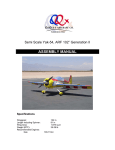
Semi Scale Yak-54, ARF 69”
ASSEMBLY MANUAL
Specifications
Wingspan:
Wing Area:
Weight (RTF):
Radio:
Recommended Engines:
2-Stroke
4-Stroke
69 in
950 sq in
8.5-9 lb
4-6 Channel W/5 Servos
1.20
1.10-1.25
1
Table of Contents
Quique’s Aircraft Company
Covering Colors
Going Over the Covering
Hardware Supplied
Additional Required Tools and Adhesives
Servo Selection
Using the Manual
Warning
Warranty Information
Section 1-Preparing Fuselage
Section 2-Horizontal Stab And Elevator Installation
Section 3-Vertical Fin Installation
Section 4-Preparation and Installation of Aileron Hinges
Section 5-Elevator, Rudder and Aileron Control Horn Installation
Section 6-Hinging Rudder & Tail Wheel Installation
Section 7-Elevator Servo Installation
Section 8-Rudder Servo and Pull/Pull Installation
Section 9-Engine Mounting and Throttle Control Installation
Section 10-Landing Gear Installation
Section 11-Fuel Tank Installation and Engine Box Completion
Section 12-Engine Cowling
Section 13-Canopy Installation
Section 14-Wing Preparation and Aileron Servo Installation
Section 15-Radio Equipment
Balancing the Model
Side Force Generators (Optional)
Control Throws
Preflight at the Field
3
4
4
5
6
7
7
7
7
8
9
13
15
17
19
21
23
26
28
31
33
35
37
39
42
43
44
46
2
Quique’s Aircraft Company
3410 Saint Paris Pike
Springfield, OH 45504
Phone: (937) 629-0339
Fax: (937) 629-0335
Email: [email protected]
Website: www.Somenzini.com
www.QQAircraft.com
Online-Support:http://www.rcuniverse.com/forum/forumid_437/tt.htm
Quique and I want to express our thanks to you for choosing our 69” Yak-54. We
think that you will enjoy one of the best flying model aerobatic airplanes
available. It is patterned after the 37% Yak-54 which took First Place honors at
2006 Don Lowe Masters Champion and 2006 Tucson Free Style Champion. The
2003 Free Style Championships in Lakeland Florida, First Place at the Don Lowe
Master competition 2003 & 2004, First Place Tucson Shoot Out 2004 Free Style,
First Place XFC 2004, precision and free-style and Third Place at the
Tournament of Championships in Las Vegas in 2002.
We have tried to prepare the best assembly manual possible along with best
support on our line of Aircraft. We are happy to announce that we have a support
forum on www.Rcuniverse.com that is being led by
Mr. Reza Gholamipour. Imagine, you are building your plane during the weekend
when we are closed and you desperately need to get an answer to your question
to continue building. Well we are happy to tell you that your question has most
likely already been asked and answered on the RC Universe forum “Quique’s
Aircraft Support.” If not, just post your question on the most appropriate thread
and have the answer in matter of hours.
Also we would like to ask you to check our support forum for any updates that
may pertain to your aircraft before starting your assembly process.
Good flying to you!
Quique, Sandra, Wayne, Molly and Reza
3
Covering Colors
Ultra-cote covering used on this 69” Yak-54 can be purchased from Horizon
Hobbies Website. The codes are as follows:
Deep Blue
True Red
White
Bright Yellow
Hanu873
Hanu866
Hanu870
Hanu872
Going Over the Covering
Before beginning the assembly of your Yak-54 , remove each part from its bag
for inspection. If you find any wrinkles in the covering, use a heat gun or covering
iron to remove them. Use caution while working around areas where the colors
overlap to prevent separating the colors. Make sure you go over the edges with
your iron as well.
4
Hardware Supplied
Wing Mounting Parts
Aileron-Hardware Pack
Engine Mount
Wheels
Canopy Hardware Pack
Tail Wheel
Elevator Hardware Pack
Rudder Hardware Pack
Fuel Tank
5
Additional Required Tools and Adhesives
• Covering/Trim iron
• Xacto knife, #11 blade
• Pacer hinge glue (PT-55)
• 5, 15 and 30-minute epoxy
• Petroleum jelly/Lithium grease
• Acetone/Alcohol swabs
• Felt-tip marker
• Pencil and Marker
• Ruler
• Drill
• Wire cutter
• Course and fine sandpaper
• Thin, medium and thick C/A
• Full threaded servo mounting screws
• Music wire/Dubro rod
• Pliers
• Masking tape
• Ultra fine point sharpie
• Double-sided tape
• Small sheet metal screws
• Rat-tail file
• Pin vise
• White glue such as Elmer’s Carpenter’s wood glue
• Round toothpick
• Velcro
Extensions:
• (2) 18” servo extensions for Ailerons
• (1) 18” or 24” servo extension for Elevators
• (1) 12” servo extension for throttle
6
Servo Selection
The servos used for the control surfaces of this Yak-54 must have a minimum of
130 ounce-inch of servo torque. In the prototype Yak-54 , we used JR8411 on all
control surfaces and on throttle we used one standard JR servo. Best results can
be obtained by using digital servos. Please do not risk your plane by using low
torque servos. This Yak-54 has large control surfaces and fully capable of any
maneuvers that a pilot is able to perform, therefore using weak servos will
increase chance of flutter and can cause you crash.
Using the Manual
This manual is divided into sections to help make assembly easier to understand
and to provide breaks between each major section. Remember to take your time
and follow the directions.
Warning
I am sure that for the most of you this is not your first venture into the World of
flying radio controlled aircraft. For those of you that may be entering this exciting
sport early on in your modeling experience and for you with vast experience, I
think we all need to be reminded of the possible dangers that are associated with
a high performance aircraft of this type. This is not a toy. This aircraft flying at a
typical weight of ten pounds and up to one hundred miles per hour will inflect
unbelievable damage to property, life and limb. This aircraft must be flown in a
safe manner at all times. You should always do a preflight check including control
surfaces hook-ups, radio operation, (please refer to your radio equipment
instruction manual for range checks and other pertinent related information) and
all other checks relating to the safe operation of this aircraft.
Warranty Information
Quique’s Aircraft Company guarantees this kit to be free from defects in both
material and workmanship at the date of purchase. This warranty does not cover
any parts damaged by use or modification. In no case shall QQAC’s liability
exceed the original cost of the purchased kit.
Customer is responsible to check all the components upon receiving of his
aircraft and notify QQAC in case of any visible damage to any parts. Customer
should not proceed with building the aircraft as some damages can compromise
the integrity of the structure of the aircraft, resulting in more damages. In no case
will such damages be covered by QQAC.
7
Section 1-Preparing Fuselage
Required Tools and Adhesive
•
•
•
Xacto knife, #11 Blade
Trim Iron
White Glue
Step 1
Use a Xacto knife with a # 11 blade
and cut away the film covering on
both sides of the fuselage for the
wing openings, Figure 1.
Some modelers may want to overlap
the film covering down inside the
fuse in the opening for the wing. For
example this type of an opening for
the wing may be done as follows.
Simply cut the film about 1/8 of an
inch to the inside of the opening for
the wing. You may then bend this
extra 1/8 inch flap of film over ninety
degrees to the inside of the fuse
opening and iron it to the edge of the
balsa sheeting over the foam. Use
the trim iron for this application.
Figure 2
Step 2
Cut the film on the horizontal stab
openings, elevator servo opening
and the arch that is for joining the
elevator halves together. Please
note that the elevator servo opening
is on the left side of the fuse.
Figure 3
Figure 1
8
Section 2-Horizontal Stab And Elevator Installation
Required Tools and Adhesive
•
•
•
•
•
Ultra fine point Sharpie
Acetone
Xacto knife, #11 Blade
Felt tip marker
Thin and thick C/A
Step 1
Center the H. Stab so that the left tip
and right tip are equal distance from
the fuselage sides. See Figure 4.
Depicted picture is not for this plane, however it’s
showing you how to ensure stab is perfectly
centered and lined up
Figure 5
Step 3
Figure 4
Mark lines on both sides of the H.
Stab top and bottom with a fine felt
tip black marker, an Ultra Fine Point
Sharpie ® works well in this
application. Later when you are
ready to remove the black lines,
acetone works best.
Step 2
Square up the H. Stab by measuring
the diagonal distance from the turtle
deck to the back corners (left and
right) of the H. Stab. They must be
the same distance. See Figure 5.
Figure 6
Step 4
Remove the H. Stab from the fuse.
Mark a line, measured 1 mm on the
inside of the two lines top and
9
bottom that you marked along the
right and left sides of the fuse.
Step 5
Use a new # 11 blade and gently cut
through the ultra cote. See Figure 7.
There are two layers, cut through the
top layer first and remove it. You
have probably cut through the
second layer. If not you may cut
through the second layer. Be very
careful not to cut into the balsa
sheeting as this will weaken the
structure of the Horizontal Stab as
the skin sheeting is important to its
structural integrity.
To do this, you may sight down the
fuselage from the rear.
See Figure 8. Make sure you are
looking straight down the middle of
the fuse.
Depicted picture is not representing production
plane color scheme
Figure 8
Step 8
Figure 7
Step 6
Use your iron to seal down the Ultracote where you removed the center
section before you make the final
attachment.
Step 7
Re-insert the H. Stab into the
fuselage. IMPORTANT: Check the
measurements again, to make sure
the H. Stab is square. Before you
make the final attachment of the H.
stab to the fuse, you must check to
see that the H. stab is parallel with
the wing.
Sight both sides of the H. stab and
compare with both sides of the wing.
If one side is lower and the other
higher, you will need to shim so both
the H. stab and the wing halves are
parallel. Now you are ready to glue
in place.
Step 9
Use thin CA and do this couple of
times. Position the plane in knife
edge attitude to make sure CA is
soaking into the slot. At the end, use
thick CA to fill up the gap. Try to
avoid accelerator until the last stage
that you are using thick CA.
Step 10
Now it’s time to do the elevators.
The elevator halves will be
connected via a CF tube.
10
There two methods that you can do
this.
Method 1
First you need to remove the dotted
line area of the tail with a sharp
xacto knife.
Figure 9
Figure 10
Figure 11
Step 10
Insert the tube in the elevator halves
so they are equal distance. Then
insert the elevator haves into the
hinges (Do not glue anything just
yet)
After moving the elevator halves
around until you achieve equal
distance from the stab, tape the stab
and elevators in the correct position
by masking tape and then CA the
tube to the elevator halves. Use thin
and medium CA and do this couple
of rounds. You do not need to use
epoxy if you let the CA dry. Make a
little fillet with medium CA around the
outside of the CF tube.
Figure 12
Figure 13
Do not glue the square pieces from
the tail section back until you have
completed the hinging for the
elevator halves to the stab.
11
There are two white stripes of
Ultracote provided in the kit that you
can use to cover the tail section of
the plane for best appearance.
tube to one and push it in further into
one of the elevator halves.
Now level both elevators with stab
just like mentioned in step 10, Fig 12
and move the tube into the other
elevator half. Make sure that the
elevator half you are pushing the CF
in has more room to accept the tube.
If you can not push the tube in any of
the elevator halves enough to avoid
hitting the other elevator half when
lined up with stab, then you can not
use this method.
Figure 14
Step 11
Go to section 4 for hinging
instructions.
Hinge the stabs first and then fit the
elevator halves.
Step 12
After your hinging is done, glue the
square pieces to the tail section and
cover them with white ultracote
provided.
You need to complete this step
before going to the next section.
Method 2
In this method you won’t need to cut
the fuse at the dotted line. Here’s
how you would attach the elevator
halves and tube.
Insert the elevators into the stab.
Move one half elevator full up and
the other full down. Now insert the
12
Section 3-Vertical Fin Installation
Required Tools and Adhesive
•
•
•
•
•
•
Acetone
Xacto knife, #11 Blade
Felt tip marker
30-minute epoxy
Alcohol Swab/Alcohol and
paper towel
Round toothpick
Figure 16
Step 1
Step 4
Insert the Vertical Fin in the fuse.
Mark a line along the V. Fin and
fuse.
Be careful to make a very shallow
cut through the film on the V. Fin so
you do not cut too deeply into the V.
Fin sheeting. A very sharp # 11
blade is helpful. Remove the black
ink line with acetone.
Step 5
Glue in place with 15 to 30 minute
epoxy glue. Remove any excess
epoxy with alcohol and a paper
towel.
Figure 15
Step 2
Mark another line about ¼” below
the first line that you drew.
Step 3
Remove the film covering as shown.
As with the Horizontal Stab there is
more than one layer of film. By
removing the film covering you will
have a stronger bond between the
Vertical Fin and the Fuse as shown.
Figure 17
Step 6
Before epoxy hardens, check to
make sure the hinge slots between
13
the rudderpost and fuselage did not
fill up with epoxy. Before the epoxy
hardens, you might be able to clean
out most of the epoxy with a round
toothpick or thin piece of 1/64
plywood. The bottom hinge slots are
where the problem might occur. If
the epoxy hardens before you clean
out the hinge slots you will have a
problem. White glue could also be
used to attach the vertical fin and
clean up with water and a piece of
paper towel would be much easier.
Figure 18
Figure 19
14
Section 4-Preparation and Installation of Aileron Hinges
Required Tools and Adhesive
•
•
Xacto knife, #11 Blade
Lithium grease/Petroleum
Jelly
• Toothpicks
• Pacer hinge glue (PT-55) or
30-minute epoxy
The hinge slots are already installed
in the balsa hinge locations on both
the fixed surfaces and the moveable
surfaces.
Step 1
Use a # 11 blade to clean the flat
hinge slot.
Step 2
Dry fit the control surfaces to ensure
there is no binding before you glue
them. The gap between the flying
surface and the control surface
needs to be at a minimum. However
we have to have enough of a gap so
full deflection is possible.
The gap should be somewhere
between 2 and 3 mm. This
procedure will take some time to do
all of the hinges but take your time
and do a nice job.
Be very careful not to get any grease
etc. on the flat part of the hinges.
Also remember that you always glue
the hinges in to the fixed surfaces
first, let the glue harden before you
glue in the control surfaces.
Remember to check for the correct
hinge gaps for rudder, elevators and
ailerons. You must have the correct
gap to insure the maximum control
deflection necessary for the best 3-D
aerobatics. For hinge attachment we
like to use Hinge Glue by Pacer.
You may use epoxy if you wish. If
you use epoxy, use an epoxy with a
curing time that will give you enough
time to work the hinges in place
before the epoxy hardens.
Make sure to clean the glue that
oozes out using alcohol swab or
acetone.
Figure 20
Step 3
Take some lithium grease or
Vaseline and apply a very small
amount on both sides of the hinge
point on the flat hinges. Quique used
a round toothpick. See Figure 21.
This will help prevent any glue in the
pivot point.
Figure 21
15
Step 4
Sealing the Control Surfaces
Figure 22
After you are done hinging the
ailerons and elevators, make sure
you seal the hinge line by using clear
ultracote. Unsealed control surfaces
may cause flutter like aileron flutter,
which may cause your plane to
crash, where sealed control surfaces
will give you better and crisper
response in flight.
For each aileron, cut ¾”x30” of clear
ultracote and seal the hinge line from
bottom using a straight edge and
trim iron.
Figure 23
For each half elevator, cut 3/8”x 9
3/4” of clear ultracote and seal the
hinge line from bottom same way as
you did your ailerons.
Figure 24
Figure 25
16
Section 5-Elevator, Rudder and Aileron Control Horn Installation
Required Tools and Adhesive
•
•
•
•
Course sandpaper
Xacto knife, #11 Blade
30-minute epoxy
Alcohol Swab/Alcohol and
paper towel
Elevator Horn Installation
Figure 27
Step 1
Cut the slots in the bottom of the left
elevator to accept the two PC Board
elevator control horns. Again, rub
your finger over the approximate
location for the cut out to find it more
easily.
Rough up the surface of the P/C
board control horn with coarse
sandpaper only where it will be glued
into the elevator. Clean the PC
boards with alcohol or acetone.
Step 2
Glue in place with epoxy (15-30
Min). Be sure that the attachment
point on the control horn is
perpendicular to the hinge line.
Figure 28
You can do above steps before or
after gluing your stabs. It’s your
choice.
Rudder Control Horn Installation
Step 1
Find the location in the rudder where
the P/C Board rudder control horn is
to be inserted. Remove the film
covering. Rough up the P/C board a
little, clean using alcohol; swab and
glue with 30-minute epoxy.
Make sure that attachment point on
the horns are equal distance to the
hinge line.
Figure 26
17
Step 2
Cut out the film over the servo
location hole.
Figure 29
Figure 32
Step 3
Figure 30
Glue the control horns in place with 5
or 30-minute epoxy. If you work at a
slow pace, perhaps you should
choose the 30-minute.
Aileron Horn Installation
Step 1
Find the location for the aileron
servos in the bottom of each wing.
Note that there are two slots there.
Remove the covering.
Figure 33
Figure 31
Figure 34
18
Section 6-Hinging Rudder & Tail Wheel Installation
Required Tools and Adhesive
•
•
•
•
Xacto knife, #11 Blade
30-minute epoxy
Alcohol Swab/Alcohol and
paper towel
Wire cutter
Step 1
Figure 36
First place the plastic tail wheel
bracket on the tail wheel wire.
Step 3
Cut the wire that will go into the
rudder to about one inch in length.
Step 4
Drill a hole in the rudder for the tail
wheel wire 13 mm from the bottom of
the rudder.
Figure 35
Step 2
Bend a 90-degree angle in the
correct direction on the tail wheel
wire that will be inserted in to a hole,
which you will soon drill into the
rudder. See Figure 36 that shows a
20mm distance from the 90-degree
bend to the bottom of the plastic tail
wheel-mounting bracket.
Figure 37
.
19
Step 6
Insert the tail wheel into rudder and
dry fit hinging to vertical fin and fuse.
Try to adjust your tail wheel bracket
to look like picture below.
Figure 38
Figure 39
Step 7
Now hinge the rudder to vertical fin
and fuse using same method in
section 4.
20
Section 7-Elevator Servo Installation
Required Tools and Adhesive
Step 4
•
•
•
•
18” or 24” servo extension
Sullivan inner nyrod
Pin vise
2 full threaded servo mounting
screws
Before installing the servo, make
sure to apply some thin CA to the
elevator servo frame inside the fuse.
Step 1
Attach 24-inch servo extension wires
to the elevator servos. You may want
to wrap the servo plug connections
with a small piece of tape.
Attach the titanium rod to the ball link
provided in the kit. Note that the rod
has opposite thread at the ends. This
is to help you tighten the rod into the
ball links by turning the rod from
middle of it. Ball links are not pre
threaded.
Attach the pc board arm to the wheel
that comes with your servo using 2-4
servo screws. Make sure to apply
some CA around the screws to
ensure their security. (Screws to hold
the elevator arm to the plastic wheel
are not provided)
Step 2
Pull the extension using your hand or
a long needle nose pier to grab the
extension that you have passed from
the elevator servo bay.
Step 3
Install the servo so the output shaft
is towards the nose of the airplane.
Figure 41
Figure 42
Figure 40
21
Step 5
Adjust the linkage size and arm so
when the servo is center your
elevators are flush with the stab. For
ease of setting this, tape the stab
and elevators using masking tape.
Figure 43
Figure 44
22
Section 8-Rudder Servo and Pull/Pull Installation
Required Tools and Adhesive
•
•
•
Pliers
Masking tape
2-4 full threaded servo
mounting screws
Step 1
Install the rudder servo the way that
output shaft is towards the tail
section of the plane. Attach the
provided composite arm to a
standard wheel arm that comes with
the servo with 2-4 servo screws and
make sure that you apply a little of
thin CA and cut the extra length of
the screws that is protruding out of
the wheel.
Figure 47
Step 3
On one end of each cable only,
attach the pull/pull cable to the
brass-threaded connection pieces
using the brass tubes pieces, both
provided, as shown in Figure 48.
Figure 45
Figure 46
Figure 48
Step 2
Step 4
Attach the ball links, provided, as
shown in the picture. Do not use the
spacer, keep it for the next step. Ball
link needs to be mounted under the
arm as pictured.
Crimp the brass tubes pieces with
pliers. Make a good firm crimp and
then it’s important to follow up with
some thin C/A applied on both ends
of the crimped brass tube pieces and
the cable.
23
Step 5
Step 9
Screw the threaded brass
connectors half way into the plastic
ball link connection on the extended
rudder servo arm as shown as
shown in Figure 49.
Slip the brass sleeve over the end of
the cable and then through the hole
in the end of the threaded brass
connector.
Step 10
Put the loose end of the cable
through the brass tube.
Make your final length adjustment on
the pull/pull cables.
Step 11
Figure 49
Step 6
Install both pull/pull cables on the
extended rudder servo control arm
as shown in the same picture. To
complete the pull/pull attachment to
the rudder control horn, you will need
to turn on your radio to hold the
rudder servo arm firmly in neutral.
Adjust the rudder servo arm with
your trim functions on the transmitter
so you have a good neutral.
Hold the threaded brass connection
piece along the side of the plastic
ball connector; you may tape it if you
wish, where about half of the threads
would be inserted into the plastic ball
connecting piece.
Step 7
Figure 50
Cross the cables and exit them
through the slots at the rear of the
fuse.
Step 8
Tape the rudder to the front of the
vertical fin so it will be held in a
neutral position also so you will be
able to determine the final length of
each pull/pull cable.
Figure 51
24
Step 12
Bend the cable over and slip the
loose end into the brass sleeve and
crimp and CA as mentioned above.
You need to use two spacers on the
ball links. One would be between the
ball link and top horn and the other in
between the ball link and bottom
horn. Make sure to use thread locker
when tightening the screw in the ball
link.
Figure 52
Figure 53
25
Section 9-Engine Mounting and Throttle Control Installation
Required Tools and Adhesive
•
•
•
Drill
#3 (0.213”) drill bit
#1 (0.228) drill bit
Step 1
Drill the engine box for your engine.
There are markings for YS and OS
engine. We have used OS 1.20 AX
for this installation. YS 110 would
also be a great choice for this plane.
Insert the blind nuts, using washer
and bolts that are provided with your
kit.
Figure 55
Step 3
Mount the engine mounts. Make
sure to use blue thread locker and
washer.
Apply a little CA to the sides of the
blind nuts to ensure they won’t be
coming loose.
Figure 56
Figure 54
Step 2
Drill the first hole on the engine
mount at 22 mm from the tip of the
mount and second one to match
your engine bolt location. Both holes
need to be centered on the mounts.
Figure 57
Step 4
Install the engine using lock nuts and
bolts provided with the kit.
26
Figure 58
Step 5
Mount the throttle servo so the
output shaft is towards the tail of the
fuse. Use ball link and rod provided
to attach the servo to the throttle
arm. For the servo side, use Du-Bro
easy connector.
Figure 59
Figure 60
27
Section 10-Landing Gear Installation
Required Tools and Adhesive
•
the gear. This will prevent the back
side from popping out.
Drill and drill bit
Landing gear comes drilled and
ready to install but you still need to
drill the holes for axles.
Step 1
Wrap 2 rounds of masking tape to
the leg of the landing gear that you
are going to drill. Mark the center of
the hole.
Figure 63
Figure 64
Figure 61
Figure 65
Figure 62
Mounting Landing Gear to
Fuselage:
Step 2
Step 3
Landing gear is made of GlassEpoxy. Before drilling, make sure to
use a piece of wood and clamp it to
Place the landing gear on the fuse in
the correct position (should be swept
forward) and bolt it to the fuse with
bolts and washers provided with the
28
kit. Make sure to use thread locker to
prevent the bolts from coming loose
under vibration.
Figure 67
Figure 66
Step 7
Put a washer on the gear axle and
place the axle though from inside of
the landing gear leg.
Step 8
Add a washer and one of the locking
nuts with the plastic locking ring
against the inside of the wheel. use a
battery-powered drill and held the
lock nut in place with pliers to attach
the lock nut. Do not tighten
completely as the wheel is not ready
to be installed.
Figure 68
Step 9
Add the other lock nut with the nylonlocking ring to the outside of the
wheel.
Figure 69
Step 10
Measure the angle for the wheel
pant. With the wheel pants attached
to the landing gear but not yet fully
tightened, place the fuselage on a
table. Have a friend hold the tail of
the airplane up to a flight line
29
position. Wheel pant should be
parallel to the fuse when plane is to
a flight line position.
Figure 70
Figure 71
30
Section 11-Fuel Tank Installation and Engine Box Completion
Required Tools and Adhesive
•
•
•
•
•
tape. This way you can easily
remove the Velcro by taking the
masking tape off, if need be.
Medium C/A
15-30 minute epoxy
Velcro
Masking tape
Double sided tape
Step 1
Assemble the fuel tank hardware as
shown. See Figure 72. Be sure the
vent tube with the short piece of fuel
tubing is cut at an angle that is
located at the top of the inside of the
fuel tank when the tank is mounted
in vertical position. The tank should
be mounted in the fuselage so it is
tall and less wide.
Figure 72
Figure 73
Figure 74
Step 2
Step 3
You can use double sided tape or
Sticky back Velcro to mount your
tank to the floor. This is to ensure
avoiding any forward or backward
movement while in flight. I used
Sticky back Velcro. Wrap couple of
rounds of masking tape to the
bottom of the tank and stick the
sticky back Velcro to the masking
Mount the tank and wrap it to the
floor with strong Velcro strap or tie
wraps.
31
Figure 77
Figure 75
Figure 76
Figure 78
Important: Make sure the tank is
firmly secured. Keep in mind that
with a full fuel tank, say 12 ounces,
with an airplane pulling 10 G’s
creates a force of 120 ounces or 7.5
pounds. With this much force the full
fuel tank might just like to take on a
mind of its own. Ten G’s would not
be uncommon in some violent 3-D
maneuvers, which this Yak-54 is
capable of doing certainly with the
control surface throws that you have
available.
Use a commercially available plug
for the line.
Step 4
Install the fuel lines. Use a T fitting
between the input line and the carb.
The straight line goes to the carb
and the other line exits from the
bottom of the firewall. You are also
advised to use a filter after the T
fitting, before the carb input.
32
Section 12-Engine Cowling
Required Tools and Adhesive
•
•
•
Pencil/Marker
Drill & 1/8” drill bit
Masking tape
Follow below steps to mark the four
cowling screw attachment location.
Figure 80
Step 1
Put some masking tape on the fuse
behind the four hardwood blocks that
you installed.
Step 2
Draw a line that matches up with the
middle of the hardwood blocks and
mark the middle of it to drill for blind
nuts.
Step 3
Install the cowl with canopy on make
sure to constraint the canopy with
masking tape. Locate the markings
on the cowl and drill a pilot hole into
the cowl and the hardwood blocks.
See below pictures.
Figure 81
Step 4
Make sure to apply some thin CA to
the hardwood block attachment and
fuse. Also apply some thin CA to
sides of blind nuts after you inserted
them. Just like the engine blind nuts
in previous section.
Step 5
Use the same method to cut the cowl
for muffler, glow driver and needle
valve of your engine.
Figure 79
33
Figure 82
Figure 83
34
Section 13-Canopy Installation
Required Tools and Adhesive
•
•
•
•
•
Xacto knife, #11 blade
Drill and 1/8” drill bit
Thin/Medium C/A
Rat-tail file
Alcohol swab
There are two holes in the fuse, one
on each side, to accept the screws to
hold the canopy in place. There is
also an anti-rotation pin to hold the
canopy in place under vibration that
needs to be glued on.
Step 1
Figure 84
Step 4
Insert the blind nuts on the inside of
the canopy hold down tabs and
tighten the 3mm screws with the
Allen wrench provided to seat the
blind nuts firmly into the plywood tab.
Find the locations for the two screw
holes. You can easily do this by
looking from inside the fuselage.
Step 2
Use your Xacto # 11 blade and
remove the Ultra-Cote.
Step 3
Now slip the canopy in place onto
the fuselage, mark and drill the holes
in the canopy plywood tabs for the
blind
Figure 85
You will install the nuts in the inside
of the tabs.
Figure 86
You should run a little thin or
medium C/A around the blind nuts
35
on the inside of the tabs to help them
stay in place.
Step 5
If you have measured correctly, you
should now be able to insert the two
canopy hold down screws into the
blind nuts. If the screws do not line
up with the blind nut hole in the
canopy hold down tab, open up the
hole in the fuse side a little with a
small rat-tail file until the screws go
in properly.
Step 6
Figure 87
First rough up the pin with sand
paper and clean with acetone or
alcohol. Then use 5-min epoxy to
glue the pin in place.
At this point you should drop a little
thin C/A glue around this hole in the
fuselage side to make the lite-ply
fuse side harder. The C/A will soak
in and make the light ply more like
regular aircraft plywood.
Step 7
Tighten the canopy screw down
firmly it won’t crush the harden liteplywood. We want to do all we can to
prevent the canopy from removing
itself during flight. It is very important
to use the provided O-Ring on the
canopy hatch like on the engine
cowling screws. Use flat steelwashers, O-Ring and another flat
steel washer. If tightened properly,
you should never loose a canopy in
flight.
Figure 88
Step 8
Step 9
Now you need to glue the provided
anti-rotation pin to the fuse.
Clean excess epoxy with alcohol
swab.
Figure 89
36
Section 14-Wing Preparation and Aileron Servo Installation
Required Tools and Adhesive
•
•
•
•
•
•
•
•
Xacto knife, #11 blade
Fine sandpaper
Thin and thick C/A
5-15 minute epoxy
Alcohol swab/Acetone
18” servo extensions (2)
Small sheet metal screws
Ruler
Figure 91
Step 4
Step 1
Now install the aileron servos.
There are four CF pins provided with
your kit. Lightly sand the CF antirotation (AR) pins on the end that
inserts into the wing sockets with
400 or very fine sand paper. Clean
with acetone or alcohol swab
Step 5
Attach an 18-inch servo extension
cable to the servo and make sure to
use a safety clip or tape the
connectors.
Step 2
Insert the pins so it goes into the
second rib and 5mm of the pin
protruding from the wing root.
Use below method described and
shown in the pictures to pass the
extension wire through the wing
panel.
Pass a music wire or a rod thru the
wing panel with a loop at one end.
Tape the servo lead using masking
tape to the music wire and pull it thru
the wing panel.
Figure 90
Step 3
Glue the pin using thin CA and then
make a fillet around the second rib
with thick CA.
Figure 92
37
Figure 93
Figure 95
Step 8
Use the two short titanium rods and
ball links provided to make the
connection between the extended
aileron servo arm and the P/C board
aileron control horn. Your final
assembly should look like Figure 96.
Figure 94
Step 6
Install the aileron servo so the output
shaft is towards the ailerons.
Step 7
Attach the plastic wheel that comes
with your servos to the PC board
arm provided, using 2-4 small
screws (not provided).
Figure 96
38
Section 15-Radio Equipment
You are now in the final stages in
completing the assembly of your
Yak-54. Mount the receiver using
following method:
1. Cover the bottom of the receiver
completely with wide masking
tape.
2. Apply some beads of medium
C/A.
3. Attach a piece of foam the size of
the bottom of the receiver to the
bottom of the receiver.
4. Attach sticky back Velcro to the
foam. To ensure that you have a
good bond, apply some CA to the
foam, then stick the Velcro to it.
5. Stick opposite side Velcro to the
tray and mount the receiver on
top of it.
The receiver floats gently but is not
fixed too firmly. If a receiver is
fastened too tight in the airplane
there could be problems with engine
vibration transmitted to the receiver.
Figure 98
Figure 99
Figure 100
Figure 97
39
Figure 101
Figure 104
Please use exact same method of
mounting your Duralite (Similar) LiIon battery. Duralite batteries have a
fail-safe stay balance circuit soldered
to battery that should not be harmed
under pressure. Make sure to use
Velcro straps to strap the batteries.
In case of receiver you do not have
to strap it if you use Industrial
Strength Velcro available at Home
Depot and other hardware stores.
Figure 102
Figure 105
Figure 106
Wrap the regulator in very thin foam
and strap it to the bottom of your
tray.
Poke a little hole in bottom of the
fuse and exit the receiver antenna.
Figure 103
40
Figure 107
There are two places already cut for
you to mount your switch. If you
need to enlarge the compartment to
fit your switch, use sharp xacto knife
blade.
Figure 109
Figure 110
Figure 108
You may need to make your own
music wire rod to connect the
receiver switch to the outside of the
fuse. You may also need to drill a
hole in the switch button to accept
the music wire. Perhaps your switch
already has the parts necessary to
make the connection outside the
fuse.
41
Balancing the Model
Perhaps one of the most important things that you need to check before you fly
your plane is your model C.G. Correctly balancing an aerobatic model is critical
to its performance and flight characteristics. An unbalanced model can be very
hard to control. Please make sure that you carefully check the C.G of your plane
before you attempt to fly it.
C.G Location
Measuring 6 ¾” from trailing edge forward to wingtip would give you best 3D and
precision flying. However, the furthest you can go from trailing edge to wing tip is
7” that means you would have a slightly nose heavy model and the aft limit from
trailing edge to wing tip is 6 ½”. See Figure 111.
Figure 111
42
Side Force Generators (Optional)
These are mounted on the wing tips. The mounting holes are already drilled in
the SFG; however you will have to open up the covering. Locate the holes in the
wing tips and remove the covering. Then mount the SFG with 2 bolts. The bind
nuts are already located inside the wing. SFGs will help you in Harrier, Knife
Edge and Roll stability. Don’t hesitate to try them.
Figure 112
43
Control Throws
Aileron (As shown in Figure 113 & 114)
Low Rate
High Rate
55 mm Up (Expo 50)
55 mm Down (Expo 50)
85 mm Up (Expo 70)
85 mm Down (Expo 70)
Figure 113
Figure 114
Elevator (As shown in Figure 115 & 116)
Low Rate
High Rate
18 mm Up (Expo 30)
18 mm Down (Expo 30)
61 mm Up (Expo 56)
61 mm Down (Expo 56)
Figure 115
Figure 116
44
Rudder (As shown in Figure 117 & 118)
Low Rate
High Rate
40 mm Right (Expo 15)
40 mm Left (Expo 15)
60 mm Right (Expo 60)
60 mm Left (Expo 60)
Figure 117
Figure 118
45
Preflight at the Field
Range Test Your Radio
Make sure you range check your radio before you attempt to fly your plane. Turn
on your transmitter with antenna fully collapsed and walk away 100-150 ft. Move
all your control surfaces and make sure everything is fine. Do this with and
without engine running.
Check Your Batteries
Make sure your receiver, ignition and transmitter batteries are fully charged.
Always double check before you fly.
Fasteners
Make sure all the bolts such as prop bolt, hatch and cowl are tight. After each
flight check for possible loose bolts.
Happy flying to you from Quique’s Aircraft Company:
Quique, Sandra, Molly, Wayne and Reza.
46