1
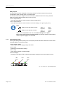
BK MIKRO 7 Control System for Tool, Object and Free Space Monitoring Operating Instructions Issue 2.01 dated 5.2.2007 MSC Tuttlingen GmbH Rudolf-Diesel-Straße 17 78532 Tuttlingen Germany Tel. +49 7461 925-276 Fax +49 7461 925-268 E-Mail [email protected] www.msc-tuttlingen.de OI: BK MIKRO 7 General Notice General Notice Safety guidelines These operating instructions contain notices which you should observe to ensure your own personal safety, as well as to protect the product and connected equipment. These notices are highlighted in the manual by a warning triangle and are marked as follows according to the level of danger: Immediate danger to life and limb of personnel and others. Non-compliance may cause death or serious (crippling) injury. Danger Hazardous situation to life and limb of personnel and others. Non-compliance may cause death or serious injury. Warning Potentially hazardous situation Non-compliance may cause slight injury; possible damage to property. Caution Notes on correct handling Non-compliance may cause damage to the product and/or damage to parts/items in the vicinity. Environmental protection Non-compliance may have an impact on the environment. Intended use Warning Rev. 2.01 dated 5.2.2007 BK MIKRO is a control system suitable for tool as well as for object and free space monitoring applications. It may only be used for the applications described in the technical documents, and only in connection with devices or components from other manufacturers which have been approved or recommended by us. This product can only function correctly and safely if it is transported, stored, set up, and installed correctly, and operated and maintained as recommended. -I- General Notice OI: BK MIKRO 7 Qualification of personnel Only qualified personnel may carry out the following activities on the control system: installation, commissioning, operation, maintenance. Qualified persons in accordance with the safety guidelines are defined as persons who are authorized to commission, to ground, and to tag circuits, equipment, and systems in accordance with established safety practices and standards. Disclaimer of liability We have checked the contents of this document for agreement with the hardware and software described. Since deviations cannot be precluded entirely, we cannot guarantee full agreement. However, the data in this manual are reviewed regularly and any necessary corrections included in subsequent editions. Suggestions for improvement are welcomed. EEC directive EMC 89/336/EEC The following applies to BK MIKRO control system: Products which carry the CE symbol meet the requirements of the EEC directive 89/336/EEC on electromagnetic compatibility. The EEC declarations of conformity and the related documentation will be maintained at the following address for inspection by the responsible officials in accordance with article 10(1) of the above stated EEC directive: MSC Tuttlingen GmbH Rudolf-Diesel-Straße 17 78532 Tuttlingen BK MIKRO 7 corresponds the specification of UL 508. Areas of use Control systems of the BK MIKRO series meet the applicable, harmonized, European standards for the respective area of applications. Fitting conditions The fitting conditions and safety notes in the operating instructions must be adhered to when commissioning and operating the devices. Copyright These operating instructions are intended for the operator and the operator’s personnel only. This document and its contents may not be disclosed to third parties, either in full or in part, by reproduction, transmission or any other means without express written authority. Non-compliance may lead to prosecution under criminal law. - II - Rev. 2.01 dated 5.2.2007 OI: BK MIKRO 7 Contents Contents 1 2 2.1 2.1.1 2.1.2 2.1.3 2.1.4 2.1.5 2.1.6 2.2 2.2.1 2.2.2 2.2.3 2.3 3 3.1 3.2 3.3 4 4.1 4.1.1 4.1.2 4.2 4.2.1 4.2.2 4.2.3 4.2.4 5 5.1 5.1.1 5.1.2 5.2 5.2.1 5.2.2 5.3 6 7 7.1 7.2 7.3 8 8.1 8.2 8.3 9 Characteristics ...........................................................................................................................3 System Components .................................................................................................................4 Control unit ...................................................................................................................................4 Characteristic properties ..............................................................................................................4 Technical data ..............................................................................................................................5 Connections .................................................................................................................................6 Light-emitting diodes ....................................................................................................................8 Rotary switches ............................................................................................................................9 Toggle switches..........................................................................................................................10 Scanner ......................................................................................................................................12 Characteristic properties ............................................................................................................12 Technical data ............................................................................................................................13 How to change ...........................................................................................................................13 Connection cable........................................................................................................................14 Mode of Operation ...................................................................................................................15 Scanning process.......................................................................................................................15 Output of results .........................................................................................................................16 Return travel monitoring .............................................................................................................16 BK MIKRO 7 with scanner TK7A – Scanning in one direction ............................................17 Teach mode = monitoring with learning function .......................................................................18 "Teach-in", the learning cycle.....................................................................................................18 "Start", the real scanning process ..............................................................................................18 Switch mode = monitoring with setting scanning range .............................................................19 Control operation "Object monitoring" ........................................................................................19 Control operation "Free space monitoring" ................................................................................19 Deflection of wand......................................................................................................................20 Examples for range settings.......................................................................................................20 BK MIKRO 7 with scanner TK7RL – Scanning in both directions.......................................21 Teach mode = monitoring with learning function .......................................................................22 "Teach-in", the learning cycle.....................................................................................................22 "Start", the real scanning process ..............................................................................................23 Switch mode = monitoring with setting scanning ranges ...........................................................24 Reference procedure .................................................................................................................24 Control operation "Object monitoring" ........................................................................................25 Scanning in one direction with scanner TK7RL..........................................................................25 Cycle Times ..............................................................................................................................26 Status Indication ......................................................................................................................27 Yellow LED .................................................................................................................................27 Red LED / Green LED................................................................................................................27 Error messages – Flashing red and green LED.........................................................................28 Installation Notes .....................................................................................................................29 Control voltage connection.........................................................................................................29 Mounting bracket........................................................................................................................30 Interference prevention ..............................................................................................................30 Ordering Information ...............................................................................................................31 Rev. 2.01 dated 05.02.2007 Page 1 of 32 Table of Figures OI: BK MIKRO 7 Table of Figures Fig. 2-1: Control unit – Connections ............................................................................................................4 Fig. 2-2: Control unit – Dimensions .............................................................................................................5 Fig. 2-3: Control unit – Light-emitting diodes ...............................................................................................8 Fig. 2-4: Control unit – Rotary switches .......................................................................................................9 Fig. 2-5: Control unit – Toggle switches ....................................................................................................10 Fig. 2-6: Definition of the rotation direction ................................................................................................11 Fig. 2-7: Range of tolerance ......................................................................................................................11 Fig. 2-8: Scanner .......................................................................................................................................13 Fig. 2-9: Connection cable – Pin configuration ..........................................................................................14 Fig. 3-1: "Start" cycle for scanning in one direction ...................................................................................15 Fig. 4-1: Handling BK MIKRO 7 with scanner TK7A..................................................................................17 Fig. 4-2: "Teach-in" for scanning in one direction ......................................................................................18 Fig. 4-3: Range settings using rotary switches for scanning in one direction ............................................20 Fig. 5-1: Handling BK MIKRO 7 with scanner TK7RL ...............................................................................21 Fig. 5-2: "Teach-in" for scanning in both directions ...................................................................................22 Fig. 5-3: "Start" cycle for scanning in both directions.................................................................................23 Fig. 5-4: Range setting using rotary switches for scanning in both directions ...........................................25 Fig. 8-1: Control voltage connection ..........................................................................................................29 Fig. 8-2: Mounting bracket .........................................................................................................................30 Purpose These operating instructions are part of the documentation of the BK MIKRO 7. They provide service personnel and system advisors with the information required to install, commission, operate and maintain the system BK MIKRO 7. © Copyright MSC Tuttlingen GmbH, 78532 Tuttlingen, 2006 These operating instructions are available as article no. 68 36 231. Subject to change without notice. Page 2 of 32 Rev. 2.01 dated 05.02.2007 OI: BK MIKRO 7 1 Characteristics Characteristics BK MIKRO 7 is a control system suitable for tool as well as for object and free space monitoring applications. The complete BK MIKRO 7 system comprises a control unit, a sensor (scanner), a connection cable. BK MIKRO 7 is based on existing BK MIKRO 4 design concepts for tool, object and free space monitoring and can be used universally for different types of monitoring by the integration of multifarious functions: Tool monitoring Monitoring of the scanning position whose precise location has been previously entered by "Teach-in", e.g. to carry out a tool check before each working cycle. Object monitoring, free space monitoring Monitoring a scanning range freely selectable via two adjusting switches, e.g. to carry out tool checks for tools with varying diameters (object monitoring), or for ejection checks (free space monitoring). Two types of scanners are available for various demands. From this two different monitoring systems result. TK7A : Scanner with mechanical backstop. TK7RL : Scanner without mechanical backstop. Principle of operation The wand of the scanner scans tools, objects or critical process spaces free of potential, in line with machine cycles. A control unit equipped with a micro-computer triggers the movement of the wand upon an external signal and passes the scanning result on to the machine control via relay contacts. The galvanically isolated inputs and outputs guarantee a high degree of operational safety and protection against interferences. Further features Scanning in one direction or in both directions Scanning in clockwise (CW) or counter-clockwise (CCW) direction Two steps for scanning intensity Output relay contacts selectable as normally open or normally closed Two ranges of tolerance for "O.K." message Indication of the scanning result by two LEDs "O.K." and "K.O." on the control unit Detection of cable breaks Rev. 2.01 dated 05.02.2007 Page 3 of 32 System Components OI: BK MIKRO 7 2 System Components 2.1 Control unit 2.1.1 Characteristic properties The control unit is available in three models preconfigured for different supply voltages. The relevant version will be marked on the rating plate: 24 VDC, 120 VAC, 230 VAC. On its front panel, the control unit is fitted with plug-in screw terminals to connect all machine inputs and outputs, supply voltage, and the scanner. The screw terminals have been arranged on two plug-in terminal blocks. These blocks are keyed so that they cannot be accidentally plugged into the wrong socket. When in operation, plastic caps cover the screws in the front. Wires to be connected are routed from the top or bottom of the unit. The scanner will be connected via a 6-wire cable to the scanner socket of the control unit. Control inputs Power supply and Control voltage 24 VDC Selection inputs (scanning direction) Scanning wand 250 mm (24 VDC); option standard: open Com Start Teach P2 0 S1 S2 S3 24 V DC 0 P1 BK MIKRO 7 270 90 90 Scanner 180 180 Scanner socket F O L R k.o. o.k. AC IN L1 N Power "k.o." "o.k." supply relay relay 230 VAC or These terminals must not be connected! 120 VAC Fig. 2-1: Control unit – Connections Note: These plugs may only be inserted or removed when the power supply has been disconnected. Caution Unmarked terminals must not be connected. Note: The nominal tightening torque for the clamping screws of the terminal connectors should be 0,5-0,6 Nm or 4,4-5,3 pound-inches (lbf in). Caution Page 4 of 32 Rev. 2.01 dated 05.02.2007 OI: BK MIKRO 7 2.1.2 System Components Technical data Housing Protection type Dimensions (W x H x D) Case mountings Power supply voltage (depending on model) Power consumption Control voltage (int./ext.) Inputs – Input current – Pulse duration Switched outputs Making/breaking capacity Operational life of relay Connections Climatological conditions Ambient temperature Storage temperature Insulating material housing, protection class II, built-in unit IP 20 45 mm x 75 mm x 107.5 mm Sectional rail, 35 mm, to DIN EN 50022 1) 24 VDC ±20% PELV Imax = 0.25 A 120 VAC Imax = 0.05 A 230 VAC Imax = 0.025 A 6 VA max. 1) 24 VDC ±20% PELV Galvanically isolated 5 mA approx. 6 ms min. 2 x 250 VAC / 30 VDC, 2 A max. 500 VA / 60 W (max.), 10 mA min. at 10 V 7 5 x 10 switching cycles Plug-in screw terminals for connecting – power supply – control inputs – selection inputs – relay outputs Scanner socket to DIN 45322, 6 pin Classification 3K3 under EN 50178 0 ºC to +50 ºC –25 ºC to +80 ºC 110 107.5 78 75 45 General tolerances ISO 2768 – mK Fig. 2-2: Control unit – Dimensions Warning Rev. 2.01 dated 05.02.2007 Note: The control unit of BK MIKRO 7 is a built-in unit (DIN EN 60950)! The system is explicit approved for operation in closed rooms (control cabinet)! 1) PELV = Protected Extra Low Voltage The voltage applied must meet the requirements for an extra low function potential with safe disconnection (PELV). Page 5 of 32 System Components 2.1.3 OI: BK MIKRO 7 Connections Power supply "24 VDC" model: "+" 24 VDC terminal Supply voltage input 24 VDC "–" 24 VDC terminal Reference potential of 24 VDC supply voltage 2) "120 VAC" and "230 VAC" models : "L1" terminal Supply voltage input, depending on model: 120 VAC or 230 VAC "N" terminal Supply voltage input, depending on model: 120 VAC or 230 VAC "+" 24 VDC terminal Control voltage for "Start" and "Teach" controlling inputs 24 VDC unregulated, output current 0.1 A max. If an external control voltage is applied, this terminal is not connected. "–" 24 VDC terminal When using the internal control voltage, this terminal must be connected to the "Com" control inputs terminal. If an external control voltage is applied, this terminal is not connected. Note: 2) Alternatively, "120 VAC" and "230 VAC" models may also be supplied with 24 VDC. In this case, "L1" and "N" terminals must not be connected. "+24 VDC" and "–24 VDC" terminals are to be connected as described above for "24 VDC" model. Note: The secondary voltage (24V) of the 120/230V Versions can be used to supply the control inputs. It is not allowed to supply other accessories which are located outside the overall enclosure. Caution Control inputs "Com" terminal Reference potential for control inputs and selection inputs "Start" terminal An input level of +24 VDC relative to "Com" terminal will trigger a "Start" cycle (the real scanning process). "Teach" terminal An input level of +24 VDC relative to "Com" terminal will trigger a learning cycle (the "Teach-in"). Page 6 of 32 Rev. 2.01 dated 05.02.2007 OI: BK MIKRO 7 System Components Selection inputs "S1" terminal "S2" terminal "S3" terminal The input signal (static) of +24 VDC relative to "Com" terminal must be stable during 10 ms min. before "Teach" or "Start". The input S3 must be connected at a wand length of 250 mm. Concerning shorter wands, S3 remains unconnected. By connecting S3, the wand is slower and therefore it oscillates less. S1/S2 selection inputs determine scanning direction! The direction of scanning depends on connected scanner with corresponding switch position. The meaning of "Clockwise/Counter-clockwise" toggle switch position on control unit may be changed by corresponding S1/S2 input signals. S1 and S2 may be open. Then is: S1=0, S2=0. Default setting Scanner TK7A Scanner TK7RL S1 S2 „CW/CCW“ Scanning Scanning 0 0 R CW CW-CCW 0 0 L CCW CCW-CW 1 0 R CW CW 2) 1 0 L CW 1) CW 1) 2) 0 1 R CCW 1) CCW 1) 2) 0 1 L CCW CCW 2) 1 1 R CCW 1) CCW-CW 1) 1 1 L CW 1) CW-CCW 1) Note: Default setting: S1 and S2 are not connected. Rev. 2.01 dated 05.02.2007 1) Scanning direction differs from "CW/CCW" switch setting: S1/S2 inputs change meaning of toggle switch. 2) Stop position must be defined by a “Teach-in” in both directions or by a reference procedure in both directions. Missing stop position causes an error message, and pulses on control inputs are ignored. Page 7 of 32 System Components OI: BK MIKRO 7 Relay outputs The terminals have been designed as dry relay contacts. By switch selection, they may be configured as either normally open or normally closed. The contacts have been designed for 250 VAC and, by additional internal circuits, protected against inductive switch-off peaks of up to 19 W (2 ms). "K.O." relay terminals These two terminals are used to indicate a fault message (K.O.). "O.K." relay terminals These two terminals are used to indicate a no fault message, i.e. a good cycle (O.K.). Note: Relay as normally closed contact: active = open inactive = closed Relay as normally open contact: active = closed inactive = open When there is no power to the unit, the contacts always will be open. Even when using relay as normally closed, they are open (like the active status) when the power supply is not connected. 2.1.4 Light-emitting diodes Three light-emitting diodes (LEDs) on the front panel provide information about the current status of the BK MIKRO 7 monitoring system: Power supply / Status Yellow LED to indicate supply voltage and status "K.O." relay Red LED to indicate fault message "O.K." relay Green LED to indicate no fault message Error messages Flashing red and green LED to indicate illegal switch settings and incorrect selection inputs LED yellow LED red k.o. LED green o.k. AC IN L1 N Fig. 2-3: Control unit – Light-emitting diodes Page 8 of 32 Rev. 2.01 dated 05.02.2007 OI: BK MIKRO 7 2.1.5 System Components Rotary switches The two rotary switches P1 and P2 on the control unit front panel are used to select the scanning mode ("Teach" or "Switch"). set the angular positions of the ranges, noted in degrees, that are controlled by object monitoring or free space monitoring. The position settings are possible in steps of 22.5°. P1 P2 0 270 0 90 180 90 180 Fig. 2-4: Control unit – Rotary switches The figure shows the setup on delivery. The meaning of the rotary switches is determined by the selected scanner together with the corresponding "Scanner" switch position. Toggle switch for scanner TK7A: for scanner TK7RL: Rotary switch Meaning P1=0 P2=0 Scanning using teach mode P1 0 P2 P1 P2 270 Scanning after setting scanning range (object monitoring and free space monitoring), at which: P1=start position (without tolerance) P2=end position (without tolerance) P1=0 P2=0 Scanning using teach mode 0<P1<360 0<P2<360 Scanning after setting scanning ranges (only object monitoring, no free space monitoring), at which: P1=range CW (rotation from stop position) P2=range CCW (rotation from stop position) Ranges of tolerance selectable: ±3° and ±10° Illegal switch settings P1=0 and P2 0 Error P1 0 and P2=0 Error will cause flashing red and green LED. Minimum angle = 5° The minimum distance between the object and the wand must be an angle of this value, so that scanning can start really, otherwise a "K.O." fault message will be indicated. Rev. 2.01 dated 05.02.2007 Page 9 of 32 System Components 2.1.6 OI: BK MIKRO 7 Toggle switches Using the six toggle switches arranged next to each other on the control unit front panel, the following functions may be set. High scanning intensity Low scanning intensity Relay N.C. (as normally closed contact) Relay N.O. (as normally open contact) Free space monitoring F O Object monitoring Counter-clockwise travel L R Clockwise travel Large range of tolerance Low range of tolerance Scanner TK7RL Scanner TK7A Fig. 2-5: Control unit – Toggle switches Note: Setup on delivery: When using scanner TK7RL: All switches are toggled to the right ! "Scanner" switch to the left ! Caution "Scanning intensity" switch Speed and force of scanner's wand in its scanning range. For "Teach-in" and "Start" cycle, in case of a good message, they amount to: "Scanning intensity" switch position Impact forces approx. 200 mN approx. 500 mN The values are valid for a wand of 150 mm length, measured on its scanning tip. Note: If this switch is in the "low" position, the lower impact force of the scanner will protect the wand from wear and tear. "Normally open contact / Normally closed contact" switch Mode of operation for the two output relays (see section "Relay outputs"). "Object monitoring / Free space monitoring" switch "O.K." result for – finding an object (object monitoring) or – not finding an object (free space monitoring) in the scanning window. Note: Free space monitoring is admissible only in combination with range setting by rotary switches P1 and P2 and connected scanner TK7A with toggle switch set to "TK7A". Page 10 of 32 Rev. 2.01 dated 05.02.2007 OI: BK MIKRO 7 System Components "Clockwise / Counter-clockwise" switch (CW/CCW) Direction of rotation, i.e. direction to which scanner moves starting from stop position. Clockwise = When rotating to the right Scanner viewed from behind (the connection side), looking up length of scanner. Fig. 2-6: Definition of the rotation direction Note: Switch position may be changed by selection inputs S1, S2 and S3 (see table in section "Selection inputs"). "Tolerance range" switch Range of tolerance for "O.K." message referred to the desired position, i.e. position learned by "Teach-in" or set by switches: small ±3° great ±10° Object sm all Desired position Scanner gre at Scanning wand Stop position Fig. 2-7: Range of tolerance Note: No range of tolerance exists for scanning in one direction using switch mode. "Scanner" switch Selection of the scanner. TK7A Scanner TK7A (scanner with mechanical backstop) TK7RL Scanner TK7RL (scanner without mechanical backstop) Rev. 2.01 dated 05.02.2007 Page 11 of 32 System Components OI: BK MIKRO 7 2.2 Scanner 2.2.1 Characteristic properties The scanner housing is cylindrical and smooth, thus permitting easy installation (e.g. by using the mounting bracket). The scanner is designed for easy access for servicing and changing the wand. Aligning the scanner is easy and requires no additional instruments or aids. We offer two types of scanners for the different applications. The sole difference between the two scanners is that the rotary movement of TK7A's wand is limited by a screw inside the housing, the mechanical backstop. TK7A – Scanner with mechanical backstop Requirement: "Scanner" switch on control unit set to "TK7A" Scanner for scanning in one direction: clockwise or counter-clockwise When a supply voltage is applied, the scanner will always move to its mechanical backstop, the so-called stop position. The scanner will be held in this position by applying a low voltage until a pulse on the "Teach" or "Start" screw triggers a scanning cycle. TK7RL – Scanner without mechanical backstop Requirement: "Scanner" switch on control unit set to "TK7RL" Scanner for scanning in both directions: CW-CCW or CCW-CW, in special cases for scanning in one direction: CW or CCW When a supply voltage is applied, the scanner persists in its momentary position. It can be turned to an other position by hand. Only after a pulse on the "Teach" or "Start" screw, it moves into its stop position, that was calculated just now, and will be held there by applying a low voltage. Using scanners TK7A and TK7RL with a different control unit than BK MIKRO 7 may damage the scanner and control unit. Note: Due to its small diameter, a wand is easily overlooked. Warning Your wand is a wearing part! Each contact with a rotating object will cause corresponding wear on the wand. This may even lead to the metal wand breaking. Due to the injury hazard this causes, users should exercise particular caution within any BK MIKRO rotating area. Page 12 of 32 Rev. 2.01 dated 05.02.2007 OI: BK MIKRO 7 Technical data Anodized aluminum IP 67 165 mm (standard), exchangeable wand 270° max. (scanner with mechanical backstop) 360° max. (scanner without mechanical backstop) Small circular connector, M12x1, 8 pin 0 ºC to +80 ºC –25 ºC to +85 ºC > 5 million at minimum scanning intensity ø1.2 circ. 150 Scanning wand Wand holder Housing Connector RO BK RO BK RO BK RO BK 26.5 angled, 8 pin Connection cable max. 114 standard length 165 mm 42.5 Protective cap ø20 9.5 Housing Protection type Wand length Scanning angle – TK7A – TK7RL Control unit connection Ambient temperature Storage temperature Scanning cycles 59 max. 98 2.2.2 System Components connector at the control unit end, 6 pin Connection cable General tolerances ISO 2768 – mK straight connector at the scanner end, 8 pin connector at the control unit end, 6 pin Fig. 2-8: Scanner Note: To prevent injury, your wand will be supplied complete with a protective cap. 2.2.3 How to change After undoing hollow screw (M3), the wand can easily be removed from its holder. Insert new wand into holder and tighten. Rev. 2.01 dated 05.02.2007 Page 13 of 32 System Components 2.3 OI: BK MIKRO 7 Connection cable Control unit and scanner are connected by a 8-wire PUR-cable: 6 pin small circular connector to DIN 45322 at the control unit end. 8 pin molded plug at the scanner end. Length 5 m, can be extended to a maximum length of approximately 25 m with extension cables. Pin configuration (at the control unit end) Small circular connector to DIN 45322, 6 pin 1 wh white 2 br brown 3 gn green 4 ye yellow 5 gr gray 6 pi pink gn 3 ye 2 br 4 5 gr 6 pi 1 wh Fig. 2-9: Connection cable – Pin configuration Note: To increase the operational life of this cable, it should not be subject to more than a minimum amount of movement during operating cycles. If this plug needs to be removed during fitting, please ensure that this pin configuration is followed on reassembly. Page 14 of 32 Rev. 2.01 dated 05.02.2007 OI: BK MIKRO 7 3 Mode of Operation Mode of Operation BK MIKRO 7 can be operated in different ways: Scanning in one direction Scanning in both directions Monitoring with learning function (Teach mode) Monitoring with setting scanning range (Switch mode) Monitoring as object monitoring or free space monitoring All modes allow return travel monitoring. 3.1 Scanning process Applying a pulse to "Start" or "Teach" terminal will trigger a scanning cycle. During scanning operation, both relay outputs will be inactive (LED "O.K." and "K.O." not illuminated). For the real scanning process, i.e. after a "Start" pulse, initially, the scanner will travel at maximum speed to the start of a given monitoring range. However, its motor will slow down to a preselected scanning speed in time before a learned position using teach mode or a preselected angle set by rotary switch using switch mode is reached. The monitoring range will then be traversed at the preset scanning speed and its related force which is to be used to scan an object or range. During the entire operation, all pulses generated by the scanner's internal encoder will be continuously processed. If the system detects that the scanner no longer moves or has exceeded the end of the monitoring range, the direction of rotation immediately changes, and the scanner will return at maximum speed into its stop position. Depending on the result of scanning the corresponding relay will be activated, and the LED belonging to will indicate the result at the control unit. "Start" cycle with CW travel using teach mode using switch mode Stop position Stop Position Vmax P1 Wand Vmax Wand Vmax Vmax Monitoring range Monitoring range Vs Vs Object "learned" position P2 Fig. 3-1: "Start" cycle for scanning in one direction Monitoring range = Range of tolerance for "O.K." message Vmax Vs = max. speed of scanner = speed of scanner preset by "Scanning intensity" toggle switch Rev. 2.01 dated 05.02.2007 Page 15 of 32 Mode of Operation 3.2 OI: BK MIKRO 7 Output of results Fault message (K.O.) A fault message will be output immediately on detection. The scanner will return to its stop position. Good cycle message (O.K.) without return travel monitoring: Results will be indicated on reaching the scanner's stop position. Note: Its return travel will not influence scanning results. – with return travel monitoring: On reaching the stop position, scanning process results will be indicated. This ensures that the scanner will have left the monitoring range at the time the results are output and that there are no further waiting periods to be considered. In the "O.K." state, the "O.K." relay will be active, while the "K.O." relay remains inactive. In all other cases, "K.O." will be indicated, i.e. the "O.K." relay will be inactive, the "K.O." relay will be active. Note: "K.O." will not only be indicated when a tool has broken but also when the scanner cannot leave its stop position for any reason (e.g. mechanical "sticking", cable break etc.). The results of a scanning cycle will remain latched until the following cycle starts. 3.3 Return travel monitoring BK MIKRO 7 allows monitoring the return travel of the wand. The signal length on "Start" input determines whether the return travel will be monitored: Before return travel begins, i.e. in the reversing point of the scanner (in the second reversing point for scanning in both directions), the system will re-read the current "Start" signal status. Return travel monitoring enabled, if "Start" signal is still present in reversing point. Return travel monitoring off, if "Start" signal has already been removed in reversing point. Return travel monitoring will detect malfunctions! Example for suitable use of return travel monitoring: BK MIKRO 7 has successfully monitored the object. But the wand is stopped by an obstacle on its return travel, cannot return into its stop position, and will block the transport of the tool. Result with return travel monitoring "K.O." Machine stops! Result without return travel monitoring "O.K." Damage of object/machine! Page 16 of 32 Rev. 2.01 dated 05.02.2007 OI: BK MIKRO 7 4 BK MIKRO 7 with scanner TK7A – Scanning in one direction BK MIKRO 7 with scanner TK7A – Scanning in one direction Note: "Scanner" toggle switch set to "TK7A" = Switch P1=0 ? Scanner TK7A yes no no Error yes Switch P2=0 ? Switch „Object“ ? no Error yes no Switch P1 P2 ? yes no Error Switch P2 270 ? yes Switch mode Teach mode Fig. 4-1: Handling BK MIKRO 7 with scanner TK7A Note: The selection inputs S1 and S2 influence in deed the rotation direction of the scanner, but do not cause any error messages. Error messages will be indicated by flashing red and green LED. Rev. 2.01 dated 05.02.2007 Page 17 of 32 BK MIKRO 7 with scanner TK7A – Scanning in one direction 4.1 OI: BK MIKRO 7 Teach mode = monitoring with learning function Requirement: Rotary switches P1=0 and P2=0 The scanning range will be determined by a learning cycle (external control signal). This mode of operation is the typical mode for tool detection applications: The system will check for the presence of the tool at the learned position 4.1.1 "Teach-in", the learning cycle The scanner will travel in its preset direction of rotation with its preset speed. If a tool is detected, its position will be stored, and the scanner returns to its stop position with maximum speed. In addition, the "O.K." relay will be activated. If the scanner rotates to a maximum of 270° without detecting any tool, the "K.O." relay will be activated. Following "Start" pulses will detect "K.O.". Learning cycle with CCW travel "learned" position Object Vs Vmax The figure shows a learning cycle with setting: Switch "L" and S1=0, S2=0, i.e. CCW travel of the scanner. vmax = max. speed of scanner vS = speed of scanner preset by "Scanning intensity" toggle switch Fig. 4-2: "Teach-in" for scanning in one direction Wand Stop position Note: A position learned during "Teach-in" will remain stored, even after removal of power to the unit. No changes after "Teach-in" and before "Start" mode, concerning: • Tool geometry (layout and dimensions) • S1/S2 selection inputs • "CW/CCW" toggle switch 4.1.2 "Start", the real scanning process The scanner will travel to the previously "learned" position of the object to check for its presence. If the tool is within the monitoring range, the "O.K." relay will be activated. If the tool is not detected, i.e. either it is missing or there is an obstacle within the scanner rotating area, the "K.O." relay will be activated. Page 18 of 32 Rev. 2.01 dated 05.02.2007 OI: BK MIKRO 7 4.2 BK MIKRO 7 with scanner TK7A – Scanning in one direction Switch mode = monitoring with setting scanning range Requirement: Rotary switches 0 P1 P2 270 Rotary switch P1 and P2 settings will define the scanning range. In this mode of operation, BK MIKRO 7 is suitable for monitoring tools with differing diameters (object monitoring) as well as for ejection monitoring (free space monitoring): Two rotary switches are used to define a scanning range which is to be monitored before each working cycle. Note: A Pulse on the "Teach" terminal do not take effect. 4.2.1 Control operation "Object monitoring" Using "Object monitoring", the control unit will change into an "O.K." state, i.e. it will issue a good message, if during a scanning cycle the operation sequence described below is followed: The scanner leaves its stop position. The angle preset via rotary switch P1 has been exceeded. The angle preset via rotary switch P2 has not been reached. 4.2.2 Control operation "Free space monitoring" The control operation "Free space monitoring" differs from the object monitoring mode in that within its monitoring range no object must be detected. Its "O.K." state is characterized by: The scanner leaves its stop position. The angle preset via rotary switch P2 has been exceeded. Caution: When performing "Free space monitoring", broken wand will always trigger an "O.K." signal. Caution Note: "Scanning intensity" toggle switch set to "high" will enable scanning operation at a higher speed. Life expectancy of the wand will not be reduced, since the unit will rarely contact a part using "Free space monitoring". Rev. 2.01 dated 05.02.2007 Page 19 of 32 BK MIKRO 7 with scanner TK7A – Scanning in one direction 4.2.3 OI: BK MIKRO 7 Deflection of wand Rotation angles will be detected by scanner encoder pulses. These pulses are derived from the rotation of the motor. For scanning, a metal needle (wand) is used which, depending on the scanning force, can be deflected. As the scanner motor is still turning when the end of this wand has already come to a stop, differences between the set and actual rotation ranges will result. For all speeds, wand deflection is compensated to a range of less than 10°. Deflection will depend, however, on wand length. 4.2.4 Examples for range settings Rotating range 0° Direction of rotation: No fault range starts: CW 45° 0 270 135° P2 L R CW No fault range starts: 180° P2 0 90 270 P2 180 180 P1 P2 0 0 270 90 270 No fault range ends: 270° No fault range: 90° 90 good 0o Direction of rotation: Rotary switches P1 P1 No fault range ends: 180° No fault range: Toggle switch at which: S1=0 S2=0 good L R 90 180 180 P1 P2 0 0 P1 0o Direction of rotation: CCW No fault range starts: P1 45° 270 90 270 No fault range ends: 180° No fault range: 135° good P2 L R 0o Direction of rotation: CCW P2 No fault range starts: 180° 180 180 P1 P2 0 0 270 90 270 No fault range ends: 270° No fault range: good 90° L R 90 180 90 180 P1 Fig. 4-3: Range settings using rotary switches for scanning in one direction Page 20 of 32 Rev. 2.01 dated 05.02.2007 OI: BK MIKRO 7 5 BK MIKRO 7 with scanner TK7RL – Scanning in both directions BK MIKRO 7 with scanner TK7RL – Scanning in both directions Note: "Scanner" toggle switch set to "TK7RL" = Only object monitoring, no free space monitoring! Special cases make possible scanning in one direction! Switch „Object“ ? Scanner TK7RL no Special modus specific wiring or relay usually not employed yes Switch P1=0 ? yes no yes Error yes Switch P2=0 ? Stop position exists ? yes no S1/S2= 00 or 11 ? no Error yes Determine stop position with "Teach-in" or "Start" (stored positions): Scanning in both Error Switch P2=0 ? no no no Stop position exists ? yes S1/S2= 00 or 11 ? no Error yes Determine stop position with reference procedure: Scanning in both Switch mode Teach mode Fig. 5-1: Handling BK MIKRO 7 with scanner TK7RL Note: The stop position of the wand must be determined by scanning in both directions (S1/S2 = 00 or 11), whether with learning function or with reference procedure. After that a scanning in one direction (S1/S2 = 01 or 10) is possible, even a "Teach-in" in one direction for only one object. Error messages will be indicated by flashing red and green LED. Rev. 2.01 dated 05.02.2007 Page 21 of 32 BK MIKRO 7 with scanner TK7RL – Scanning in both directions 5.1 OI: BK MIKRO 7 Teach mode = monitoring with learning function Requirement: Rotary switches P1=0 and P2=0 The scanning ranges will be determined by a learning cycle (external control signal). This mode of operation is the typical mode for tool detection applications: The system will check for the presence of the tools at the learned positions. 5.1.1 "Teach-in", the learning cycle The scanner will first travel from its initial position with its selected speed in the preset direction. If a tool is detected, its position will be stored. Then the wand will travel in opposite direction with its preset speed to determine the position of the second tool, and also store this position. Using this two positions the system will calculate the new zero position of the wand as the center between the two tools. Finally the wand will turn into its zero position, the stop position, and will be held there by applying a low voltage. In addition the "O.K." relay will be activated. If the system can detect only one tool or not a single one, the "K.O." relay will be activated. After such a faulty learning action, the wand will return to its old stop position. Following "Start" pulses will detect "K.O.". Learning cycle with CW-CCW travel Stop position Initial position Vs The figure shows a learning cycle with setting: Switch "R" and S1=0, S2=0, i.e. first CW travel, then CCW travel of the scanner. Vs Vmax Object 2 "CCW" "CW" "learned" positions Object 1 vmax = max. speed of scanner vS = speed of scanner preset by "Scanning intensity" toggle switch Fig. 5-2: "Teach-in" for scanning in both directions Note: Positions learned during "Teach-in" will remain stored, even after removal of power to the unit. No changes after "Teach-in" and before "Start" mode, concerning: Tool geometry (layout and dimensions) Changes of S1/S2 selection inputs or "CW/CCW" toggle switch are allowed after "Teach-in". Page 22 of 32 Rev. 2.01 dated 05.02.2007 OI: BK MIKRO 7 5.1.2 BK MIKRO 7 with scanner TK7RL – Scanning in both directions "Start", the real scanning process The scanner will travel to the previously "learned" positions of the objects to check for their presence. In so doing, the wand will first move in the preset direction, then in opposite direction. If the tools are within the monitoring ranges, the "O.K." relay will be activated. • If one of the two tools is not detected, (i.e. either it is missing or there is an obstacle within the scanner rotating area) the "K.O." relay will be activated. "Start" cycle with CW-CCW travel using teach mode Stop position The figure shows a "Start" cycle with setting: Switch "R" and S1=0, S2=0, i.e. first CW travel, then CCW travel of the scanner. Vmax Vmax Monitoring range "CCW" Vmax Monitoring range "CW" vmax = max. speed of scanner vS = speed of scanner preset by "Scanning intensity" toggle switch Vs Object 2 "CCW" "CW" "learned" positions Vs Fig. 5-3: "Start" cycle for scanning in both directions Object 1 Note: The rotation sequence of "Start" cycle may differ from that of learning cycle. Scanning in one direction is possible (select corresponding inputs S1, S2), when stop position is detected. Rev. 2.01 dated 05.02.2007 Page 23 of 32 BK MIKRO 7 with scanner TK7RL – Scanning in both directions 5.2 OI: BK MIKRO 7 Switch mode = monitoring with setting scanning ranges Requirement: Rotary switches 0 < P1 < 360 and 0 < P2 < 360 Rotary switch P1 and P2 settings will define two scanning ranges. In this mode of operation, BK MIKRO 7 allows only object monitoring: Two rotary switches are used to define two scanning ranges which are to be monitored before each working cycle. Note: A Pulse on the "Teach" terminal do not take effect. 5.2.1 Reference procedure The first "Start" cycle after supply voltage has been applied, finds out the stop position of the scanner by a so-called reference procedure. Note: Carry out reference procedure with "Scanning in both directions". 1. After "Start" pulse the scanner rotates to the first object with selected speed in preset direction. 2. From there it moves back in opposite direction for the preset value of the selected direction to the so-called stop position, e.g. P1 means CW rotation. 3. Without stop it travels on at most towards the second value into the reversing point, when a second object is not found before. 4. After that the scanner will return to its stop position. Result: "O.K." Both objects detected Movement as described above. "K.O." No object detected Rotation towards 360°, back to initial position, that becomes stop position. First object detected, no second object within the preset range Movement as described above, stop position is determined by the detected first object. Reference procedure is necessary: • after interruption of power supply • after changing the switch settings P1 or P2 • after changing the "Scanner" switch from "TK7A" back to "TK7RL" Note: Only after a reference procedure the scanner persists in its stop position while power supply is applied. The S1/S2 selection inputs and the "CW/CCW" toggle switch determine the sequence of rotation directions. Changes of S1/S2 selection inputs or of toggle switch "CW/CCW" are allowed after reference procedure. Page 24 of 32 Rev. 2.01 dated 05.02.2007 OI: BK MIKRO 7 5.2.2 BK MIKRO 7 with scanner TK7RL – Scanning in both directions Control operation "Object monitoring" The second "Start" pulse starts the real scanning process of object monitoring within two ranges. The control unit will change into an "O.K." state, i.e. it will issue a good message, if during a scanning cycle the operation sequence described below is followed: The scanner leaves its stop position. Both objects are detected within the rotation ranges P1 and P2. "Start" cycle with CW-CCW travel using switch mode Monitoring range "CCW" Stop position The figure shows a "Start" cycle with setting: Switch "R" and S1=0, S2=0, i.e. first CW travel, then CCW travel of the scanner. Minimum angle Vs Vmax Vs Monitoring range "CW" Vmax P2 P1 vmax = max. speed of scanner vS = speed of scanner preset by "Scanning intensity" toggle switch Fig. 5-4: Range setting using rotary switches for scanning in both directions 5.3 Scanning in one direction with scanner TK7RL Requirement: As soon as the stop position has been detected (i.e. after a "Teach-in" with scanning in both directions or a reference procedure with scanning in both directions) the scanning in one direction is possible with scanner TK7RL, too. For scanning in one direction set the selection inputs S1 and S2 corresponding to the description in table of section "Selection inputs". Do not change setting of "Scanner" switch. Teach mode Scanning in one direction of already "learned" objects A "Start" will monitor both of the known objects individually: Scanning in CW direction or in CCW direction. Scanning in one direction of "new" objects Scanning in one direction allows also learning the position of unknown objects. Stop position remains valid: The wand will return to its stop position, determined by "Teach-in" in both directions, in any case. Switch mode Scanning in one direction of the preset monitoring ranges A "Start" pulse will monitor both of the monitoring ranges individually: Scanning in CW direction or in CCW direction. Rev. 2.01 dated 05.02.2007 Page 25 of 32 Cycle Times 6 OI: BK MIKRO 7 Cycle Times Scanning times The following cycle times hold for systems with scanner TK7A or TK7RL: "Intensity" Switch TK7A – Scanning in one direction Angle "Teach" "Start" TK7RL – Scanning in both direction Angle "Teach" "Start" 15° 210 ms 150 ms ±15° 320 ms 260 ms 15° 170 ms 120 ms ±15° 210 ms 190 ms 90° 580 ms 280 ms ±45° 720 ms 370 ms 90° 330 ms 250 ms ±45° 360 ms 300 ms 180° 1000 ms 390 ms ±90° 1200 ms 470 ms 180° 520 ms 370 ms ±90° 550 ms 410 ms 270° 1440 ms 510 ms ±180° 2400 ms 720 ms 270° 700 ms 470 ms ±180° 1100 ms 630 ms Note: "Cycle" time means: wand returned to stop position. "Measuring time" for "K.O." in a "Start" cycle ½ cycle time when using scanner TK7A, i.e. for scanning in one direction. Times hold for setting "Tolerance" switch to "small", switch set to "great" will slightly increase "Start" cycle times! Page 26 of 32 Rev. 2.01 dated 05.02.2007 OI: BK MIKRO 7 7 Status Indication 7.1 Yellow LED Status Indication Fast flashing = Self-test After power-up, the system will carry out a self-test indicated by fast flashing of this yellow LED. Steady illumination = Ready to operate Following its self-test, the system is ready to operate. The LED stops flashing and remains steady. Slow flashing = Scanner fault The system has detected a scanner fault: Scanner is missing or has motor fault. Control cable is not correctly connected, e.g. even cable break. Outputs will be switched inactive, the unit will remain in its present state, indicated by slow flashing of this yellow LED. 7.2 Red LED / Green LED Steady illumination = Indication following scanning cycle The red LED indicates a fault message. The green LED indicates a no fault message. Flashing = Illegal settings A flashing red and green LED simultaneously indicates that one or more of the switches is incorrectly set, and/or the S1/S2 selection inputs have been connected incorrectly. Rev. 2.01 dated 05.02.2007 Page 27 of 32 Status Indication 7.3 OI: BK MIKRO 7 Error messages – Flashing red and green LED Check the following settings to remove the error messages. "Scanner" toggle switch (TK7A/TK7RL) "Object monitoring / Free space monitoring" toggle switch (O/F) Rotary switches P1 and P2 Selection inputs S1 and S2 The error messages are distinguished by connected scanner with corresponding setting of toggle switch to "TK7A" or "TK7RL". Scanner TK7A, "Scanner" switch set to TK7A Teach mode [requires: P1=0, P2=0] Error Correction no free space monitoring, only object monitoring F O Switch mode [requires: 0 P1 P2 270] Error Correction P1 P2 P1 P2 P2 270 P2 270 Teach mode [requires: P1=0, P2=0] Error Correction no free space monitoring, only object monitoring * O Determination of stop position only with "Teach-in" S1/S2=01 00 or 11 in both directions: Selection inputs S1/S2 = 00 or 11 Having determined the stop position "Teach-in" in one direction is also possible besides scanning in one direction. Note: Stop position will not change! S1/S2=10 00 or 11 Switch mode [requires.: P1 0, P2 0] Error Correction no free space monitoring, only object monitoring * O for object monitoring P1=0, P2 0 P1 0 P2=0, P1 0 P2 0 S1/S2=01 00 or 11 in both directions: Selection inputs S1/S2 = 00 or 11 S1/S2=10 Having determined the stop position scanning in one direction is also possible. 00 or 11 Signal to "Teach" without effect, only "Start" pulse ! for object monitoring or free space monitoring Scanner TK7RL, "Scanner" switch set to TK7RL Signal to "Teach" without effect, only "Start" pulse ! Determination of stop position only with reference procedure * Special function of the relays Page 28 of 32 Rev. 2.01 dated 05.02.2007 OI: BK MIKRO 7 Installation Notes 8 Installation Notes 8.1 Control voltage connection Power supply and Control voltage GND Power supply 24 VDC GND Control voltage GND 24 VDC 24 VDC Start Teach-in + – 24 V DC Com Start Teach S1 AC IN N L1 k.o. C NO/NC Start Teach-in S3 + – 24 V DC Com Start Teach S1 o.k. C NO/NC AC IN N L1 k.o. C NO/NC S2 BK MIKRO 7 24 VDC common power and control voltage supply S2 S3 o.k. C NO/NC BK MIKRO 7 24 VDC separate control voltage Control voltage ext. GND Start Teach-in + – 24 V DC Com Start Teach S1 AC IN N L1 k.o. C NO/NC ext. 24 VDC Start Teach-in S3 + – 24 V DC Com Start Teach S1 o.k. C NO/NC AC IN N L1 k.o. C NO/NC S2 Power supply Power supply BK MIKRO 7 230 VAC (120 VAC) internal control voltage BK MIKRO 7 230 VAC (120 VAC) external control voltage S2 S3 o.k. C NO/NC Fig. 8-1: Control voltage connection Rev. 2.01 dated 05.02.2007 Page 29 of 32 Installation Notes 8.2 OI: BK MIKRO 7 Mounting bracket The delivering program offers a mounting bracket for the scanner as accessories. Article no. 61 07 165 contains the following parts: Designation Material Part no. Mounting bracket AlCuMgPb, F 38, thickness 8, naturally anodized 2 cheese head screws with hexagonal hole M3x40 8.8 zinced 3 2 self-securing nuts M3 8 zinced 4 1, 2 General tolerances ISO 2768 – mK burred edges Fig. 8-2: Mounting bracket 8.3 Interference prevention All inputs are opto-decoupled and thus maximally protected against interference voltage peaks, as caused, for example, by inductive sources. Relay outputs are protected by varistors against inductive interference voltage peaks. Depending on the type of load used, further interference suppression measures may be necessary. To ensure optimum operational safety, suppression measures, if required, must be taken at source, i.e. directly where interference is caused. Possible additional noise filters: • RC combination (included in the contactor suppliers' product ranges) • Varistors • Diodes Page 30 of 32 Rev. 2.01 dated 05.02.2007 OI: BK MIKRO 7 9 Ordering Information Ordering Information Control unit Article no. BK MIKRO 7 24 VDC 63 04 220 BK MIKRO 7 120 VAC 63 04 222 BK MIKRO 7 230 VAC 63 04 221 Scanner Article no. TK7A (scanner with mechanical backstop) 63 04 234 TK7RL (scanner without mechanical backstop) 63 04 235 Connection BK MIKRO 7: Control unit – Scanner Length Article no. Control cable "Conprox", straight connector 5m 62 04 248 Control cable "Conprox", straight connector 15 m 62 04 250 Control cable "Conprox", angled connector 5m 62 04 249 Extension cable 5m 62 04 210 Extension cable 10 m 62 04 211 Extension cable 15 m 62 04 212 2m 62 04 213 Extension cable incl. mounting socket Accessories and spare parts Article no. Scanning wands BK MIKRO 7: – Length 165 mm (standard) 10 pieces 62 04 022 – Length 250 mm 10 pieces 62 04 216 – HSS, length 165 mm 1 piece 62 04 215 – HSS, length 250 mm 1 piece 62 04 231 Wand holder for short breakable chips incl. wand 1 piece 62 04 263 Wand holder incl. wand 1 piece 62 04 026 Mounting bracket 61 07 165 Operating Instructions Article no. BK MIKRO 7 68 36 231 Rev. 2.01 dated 05.02.2007 Page 31 of 32 Ordering Information Page 32 of 32 OI: BK MIKRO 7 Rev. 2.01 dated 05.02.2007