1
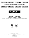
KTT-20E
ELECTRIC FLOOR MODEL TILTING KETTLE
INSTALLATION – OPERATION – MAINTENANCE
BLODGETT OVEN COMPANY
www.blodgett.com
44 Lakeside Avenue, Burlington, Vermont 05401 USA Telephone: (802) 658-6600 Fax: (802) 864-0183
S00049 Rev1D (12/14)
IMPORTANT NOTES FOR INSTALLATION AND OPERATION
It is recommended that this manual be read thoroughly and that all instructions be followed
carefully.
This is the safety alert symbol. It is used to alert you to potential
personal injury hazards. Obey all safety messages that follow this
symbol to avoid possible injury or death.
WARNING: Improper installation, operation, adjustment, alteration,
service or maintenance can cause property damage, injury or death.
Read the installation, operating and maintenance instructions
thoroughly before installing, operating or servicing this equipment.
Intended for commercial use only. Not for household use.
NOTICE: Contact the factory, the factory representative or local service
company to perform maintenance and repairs
2
TABLE OF CONTENTS
DESCRIPTION
PAGE
IMPORTANT NOTES FOR INSTALLATION AND OPERATION ................................. 2
SERVICE CONNECTIONS ......................................................................................... 4
1.0 INSTALLATION INSTRUCTIONS ........................................................................ 5
2.0 INTRODUCTION .................................................................................................. 6
3.0 OPERATION INSTRUCTIONS ............................................................................. 7
4.0 CLEANING INSTRUCTIONS ............................................................................... 9
5.0 ADDING WATER ................................................................................................. 11
6.0 VENTING INSTRUCTIONS ................................................................................ 12
7.0 TILTING INSTRUCTIONS .................................................................................. 12
3
SERVICE CONNECTIONS
SERVICE CONNECTIONS
Electrical connection to be as specified on data plat.
COLD WATER: 3/8” O.D. tubing to faucet. (OPTIONAL)
HOT WATER: 3/8” O.D. tubing to faucet. (OPTIONAL)
ELECTRICAL CHARACTERISTICS
20 gallons
76 litres
kW
Phase
(TOTAL)
12
NOMINAL AMPS PER LINE
208V
220V
240V
380V
415V
480V
600V
1
57.6
54.5
50.0
N/A
N/A
N/A
N/A
3
33.4
31.5
28.9
18.3
16.7
14.5
11.5
SAFETY RELIEF
VALVE
DIMENSIONS ARE IN INCHES [MM]
4.12 [105]
225 lbs. [102 kg]
1.63 [41]
5.50 [140]
24.25 [616]
SHIPPING WT.
MIN. CLEARANCE
0
R.H. SIDE
3 [76]
L.H. SIDE
7.25 [184]
BACK
FLANGED FOOT DETAIL
4 EQUALLY SPACED
Ø7/16" [11mm] HOLES
ON 3 [76] B.C.
31 [787]
OPTIONAL FAUCET
6 [152]
20.88 [530]
53.62 [1362]
Ø21 [533]
18 [457]
KTT-20E
CAPACITY
30.62 [778]
MODEL
20.5 [521]
24 [610]
15 [381]
8.88 [225]
12.5 [318]
51 [1295]
4
10 [254]
1.0 INSTALLATION INSTRUCTIONS
The appliance must be installed in accordance with:
1. State and/or local codes.
2. In the USA, the National Electrical Code, ANSI/NFPA-70 (Latest Edition). In Canada, the
Canadian Electrical Code, Part 1, CSA standard C22.1 (Latest Edition)
INSTALLATION
1. Select a location to provide drainage directly below the pour path. Allow sufficient rear
clearance from wall for kettle to tilt freely and completely without obstruction.
2. Mark hole locations through flanged adjustable feet. Remove feet.
3. On hole locations marked, drill holes and insert expansion shields to accommodate 5/16" size
lag bolts.
4. Reposition kettle. Level kettle by making necessary adjustments on flanged feet.
5. Bolt down kettle and seal with Silastic or other equivalent sealing compound. Sealant must
be applied not only to bolt heads but also around flanges making contact with floor surface to
fulfill NSF International requirements. Wipe off excess sealant immediately.
6. A control box with power supply equivalent to electrical rating of kettle should be located
conveniently nearby.
7. A waterproof electrical connection from power supply to rear of control housing must be
provided.
8. Ground kettle to terminal provided inside control housing.
9. Turn power ON and check for proper operation.
5
2.0 INTRODUCTION
DESCRIPTION
Models KTT-20E (20 gallon capacity) is electrically powered, self-contained, tilting kettles. Each
model has a jacket of double-wall construction forming a sealed reservoir around the lower twothirds of the kettle. The reservoir is charged with distilled water. Kettles are equipped with a
“clean lock” to hold kettle in cooking position or 105 degrees for ease of cleaning, removable
electric heating element and controls, including a low water cutoff device for protection of the
heating element. All models are of identical construction, except for kettle size and element
heating capacity.
BASIC FUNCTIONING
Self-contained kettles operate by generating steam in the kettle reservoir. The sequence of
operation is as follows:
1. Operator turns the power switch to the ON position and sets the temperature control dial at
the desired setting from 1 to 10 (90°F to 285°F, 32°C to 140°C, jacket temperature).
2. Control circuit is normally completed to the temperature control if the following conditions
exist:
a. Water level in the kettle reservoir is adequate to prevent circuit interruption by the low
water cut off device. An activated cutoff is indicated by the amber low water light.
b. Kettle is in vertical position with circuit completed through the tilt interlock switch.
3. Thermostatic control contacts close to energize contactor coils.
4. Power is supplied to the elements through closed power contactors.
5. As the temperature of water rises in the kettle reservoir, increase in steam pressure is
indicated on the pressure gauge.
When the temperature of steam in the reservoir reaches the setting shown on the temperature
control dial, the temperature controller opens to break the contacts and shut off the heating
element. On/off cycles will occur as required to maintain temperature control.
6
3.0 OPERATION INSTRUCTIONS
1. Ensure that the external electrical shut-off to kettle is on.
2. Check pressure gauge for correct cold kettle reading. Reading should be 25 - 30 In. Hg (84 100 kPa) of vacuum. If reading is not low enough, follow VENTING procedure prior to using
kettle.
3. Place power switch in ON position.
4. Preheat kettle by placing thermostat knob at ‘10' and wait until TEMPERATURE light goes
off.
5. Add food to be cooked into kettle.
NOTE
PREHEATING SHOULD NOT BE USED WHEN COOKING MILK AND EGG FOOD PRODUCTS
WHICH ADHERE TO HOT COOKING SURFACES. THESE FOODS SHOULD BE PLACED INTO
KETTLE BEFORE HEATING IS BEGUN.
6. Place thermostat knob at required temperature setting from 1 to 10 coinciding with a
temperature range indicated by the table below.
Approximate cooking temperatures with water at various thermostat settings are as follows:
THERMOSTAT SETTING
1
2
3
4
5
6
7
8
9
10
APPROXIMATE (JACKET) TEMPERATURE
140° Fahrenheit
155° Fahrenheit
172° Fahrenheit
187° Fahrenheit
205° Fahrenheit
223° Fahrenheit
240° Fahrenheit
255° Fahrenheit
271° Fahrenheit
285° Fahrenheit
60° Celsius
68° Celsius
78° Celsius
86° Celsius
96° Celsius
106° Celsius
116° Celsius
124° Celsius
133° Celsius
140° Celsius
7. When cooking is finished set thermostat knob and power switch to OFF position.
8. Pour finished product from kettle using tilt handle. Be careful to avoid splashing.
9. Add water to kettle for cleaning purposes.
10. Wash kettle thoroughly. See CLEANING procedure.
7
4.0 TROUBLESHOOTING
No preventive maintenance is required other than adhering to the Cleaning Procedure
instructions.
SAFETY VALVE MAINTENANCE AND TESTING
CAUTION! Under normal operating conditions a “try lever test”
should be performed every two months. Under severe service
conditions, or if corrosion and/or deposits are noticed within the
valve body, testing must be performed more often. A “try lever test”
should also be performed at the end of any non-service period.
CAUTION! Hot, high pressure fluid may be discharged from body
drain and vent during “try lever” test. Care must be taken to avoid
any bodily contact.
CAUTION! High sound levels may be experienced during “try lever”
test. Wear proper safety equipment and exercise extreme care! Test
at, or near, half of the operating pressure by holding the test lever
fully open for at least two seconds to flush the valve seat free of
sediment and debris. Then release lever and permit the valve to
snap shut.
If lift lever does not activate, or there is no evidence of discharge,
turn off equipment immediately and contact a licensed contractor or
qualified service personnel.
8