1
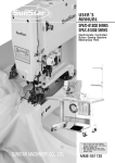
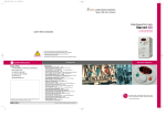
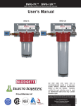
Service Manual
Model - XL50EC
Grilled Chicken Oven with
Semi-automatic Cleaning System
Blodgett Oven Co. ~ 44 Lakeside Ave., Burlington, VT 05401 ~ 800-331-5842 ~ www.blodgett.com ~ 12/1/08
44 Lakeside Avenue, Burlington Vermont 05401 U.S.A.
Telephone: 1-(800)331-5842 (802)860-3700 D Fax:(802)652-2814
XCEL-50EC KFC OVEN STARTUP/ACTIVATION CHECKLIST
Return form to BLODGETT when job is complete. Submit one form with each unit installed.
SERIAL NO.
MODEL_______________DATE OF INSTALLATION
STORE ID
SERVICE AGENCY
ADDRESS
ADDRESS
CITY________________________ STATE_______ ZIP
CITY________________________ STATE_______ ZIP
PHONE:(______)
PHONE:(______)______________ MECHANIC
ELECTRIC: V
The rating plate is located on the back of the oven.
VOLTAGE_____________ PHASE
OPERATIONAL START-UP/ACTIVATION PROCEDURE
Information can be found in the Startup Guide or by contacting the factory. Write in N/A if not applicable.
1. Flush Water inlet hose for 30 seconds to remove all debris in the water
line before attaching the water hose to oven. Verify water is cold.
Yes
2. Is the oven level? If no, level the unit.
Yes
3. Drain pipe and drain actuator are installed?
Yes
4. Does drain hose reach open drain? Cut to length as needed.
Yes
Attach the 90_ pvc fitting to the end of the hose.
5. Is the cleaning solution tray installed? Be sure there are no kinks in
Yes
the chemical line.
No
No
No
No
No
6. COMPONENT FUNCTION TESTS: In “Diag Input” mode, check the operation of the following;
_____ 1. Door Strike Switch
_____ 2. Door Proximity Switch
7. COMPONENT FUNCTION TESTS: In “Diag Output” mode, check the operation of the following;
8.
9.
10.
11.
12.
13.
14.
15.
16.
17.
18.
_____ 1. Heat On (Light on the SS Relay)
_____ 8. Quench Solenoid
_____ 2. Fan High
_____ 9. Chem Pump
_____ 3. Fan Low
_____ 10. Recirc Pump
_____ 4. Fan Forward
_____ 11. Door Lock
_____ 5. Fan Reverse
_____ 12. Contactor
_____ 6. Cooling Fan
_____ 13. Water Solenoid
_____ 7. Drain Valve (look down drain)
_____ 14. Recirc Valve
Set the water pressure to 20-PSI flowing. Test 2 quarts in 50 seconds.
Verify there are no water leaks from the connector to the cavity.
Verify blower wheel wing screw is tight.
Verify all metal edges are deburred.
Verify the baffle and racks are installed properly.
Verify incoming voltage matches Data Tag of oven.
Applied voltage between L1 to L2 ______ L2 to L3______ L1 to L3 ______
Amp draw at terminal block L1_____ L2 _____ L3 _____
Turn oven on. Allow heat to cycle 3 times. Shut oven off.
Apply your company sticker on “Door Lock” cover.
Remove all protective vinyl from exterior sheet metal.
Yes
Yes
Yes
Yes
Yes
Yes
No
No
No
No
No
No
Yes
Yes
Yes
No
No
No
Fax completed form to Blodgett at 802-652-2814.
This appliance may be equipped with proprietary features and/or components which are for the exclusive use of the customer indicated above.
Further, there may be procedures and/or methods being utilized in preparing this customer’s product which may be proprietary. I hereby certify
that this information will be held in confidence and not disclosed to any third party for whom it is not intended.
I hereby certify that the above indicated Blodgett XCEL-50EC KFC oven has been installed, activated and is in good working order.
Service Agent’s Signature
FORM/Serv.27
Store Manager’s Signature
(White Copy To Blodgett Warranty Department, Yellow Copy To Customer, Pink Copy To Service Agency)
P/N 52246 Rev A
FAST ~ VVC for XL-50EC Oven
Second Level Programming
(The oven needs to be in the “ON” position)
Press and hold the (P) Button
Scroll to “Programming”
for 3 seconds
Press the (P) Button
Enter Service Code “2222”
Press the (P) Button
Scroll to “Diag Input”
Strike Switch
Hinge Switch (Proximity)
Press button 1, open closed door
Press button 2, open closed door
Press the (P) Button
Scroll to “Diag Output”
Press the (P) Button
Press and hold # button to test
1
2
3
4
5
6
7
8
9
10
11
12
13
14
Component Function Test:
S/S Heat Relay
Fan High
Fan Low
Fan Forward (CCW)
Fan Reverse (CW)
Cooling Fan (Blows in)
Drain Valve Actuator (N.C.)
Quench Solenoid
Chemical Pump
Recirc Pump
Door Lock Motor
Mechanical Contactor (N.C.)
Water Fill Solenoid
Recirc Solenoid
Scroll to exit
Press the (P) Button
FAST ~ VVC for XL-50EC Oven
Second Level programming
Press and hold the
(P) Button for 3 seconds
Scroll to programming
Press the (P) Button
Code 2222
Press the (P) Button
Scroll to “Clean Cycle”
Press the (P) Button
Corresponding Name
Pre-Rinse Time
Fill Time
Chemical Time
Wash Time
Rinse Time
Pump Fill Time
Purge Time
Final Rinse Time
Flush Time
Drain Time
Set Temp
Fan Speed
Fan Reverse Time
Soil Shield
Full Bottle Time
Press ▼ to scroll through times
3:00
1:45
3:45
45:00
5:00
2:30
2:00
10:00
2:00
3:00
180F
Very High
3:00
NO
17:12
To exit programming
Press ▼ to “EXIT”
Press the (P) Button
NOTE: Fill times are based on 20 PSI inlet flow pressure
XL-50EC Relay Board – Rear View
Call outs of “J” connectors and #1 pin location
J2-Pin #1
J3-Pin #1
J20-Pin #1
J6-Pin #1
J18-Pin #1
J7-Pin #1
J14-Pin #1
J19-Pin #1
J11-Pin #1
J1-Pin #1
J41-Pin #1
XL-50EC - Trouble shooting test points
~ Using the control diagnostic outputs ~
Test Points on Relay Board
Black lead
Red Lead
Voltage
AC + DC
Key #
Output Components
1
S/S Heat Relay
Connector J18-Pin #5(Empty)
Connector J20-Pin #2-OR
24 VDC
6
Cooling Fan
Connector J18-Pin #5(Empty)
Connector J3-Pin#11-GY
24 VDC
7
Drain Actuator
Connector J18-Pin #5(Empty)
Connector J18-Pin #7-OR
24 VDC
8
Quench Solenoid
Connector J18-Pin #5(Empty)
Connector J2-Pin #6-OR
24 VDC
9
Chemical Pump
Connector J18-Pin #5(Empty)
Connector J2-Pin #8-V
24 VDC
Connector J18- Pin#3-BL
24 VDC
24 VDC
13
Fill (Spritzer) Solenoid Connector J18-Pin #5(Empty)
12
*** Mech. Contactor
Connector J18-Pin #5(Empty)
Connector J6-Pin #5-OR
10
Recirc Pump
Terminal #12, 7+8-WH on rear
24 volt transformer
Connector J6- Pin #8-V
Recirc Solenoid
Terminal #12, 7+8-WH on rear
24 volt transformer
Connector J3-Pin #6-Y
14
***
NOTE: Component is normally energized, de-energizes during testing
Key #
Motor Inverter Drive
2
Fan High Speed (75Hz)
3
4
5
24 VAC
Fan Low Speed (60Hz)
Fan Forward (45Hz)
Fan Reverse (45Hz)
Test Points on Relay Board
Black lead
Red Lead
Connector J11-Pin #1-BK
Connector J11-Pin #1-BK
Connector J11-Pin #1-BK
Connector J11-Pin #1-BK
Voltage
AC + DC
Connector J2-Pin#9-GY
23 VDC
Connector J2-Pin#10-GY
0.0 VDC
Connector J2-Pin#9-GY
0.0 VDC
Connector J2-Pin#10-GY
23 VDC
Connector J2-Pin#9-GY
23 VDC
Connector J2-Pin#10-GY
23 VDC
Connector J2-Pin#11-GY
0.0 VDC
Connector J2-Pin#12-GY
23 VDC
Connector J2-Pin#9-GY
23 VDC
Connector J2-Pin#10-GY
23 VDC
Connector J2-Pin#11-GY
23 VDC
Connector J2-Pin#12-GY
0.0 VDC
NOTE: Logic for motor control connects return circuit. "0" volts means circuit completed
Component Resistance Readings
Part Name
Ohms
Part Name
Ohms
24VDC Power Supply, Across +V & -V
(Unwired DC Voltage)
326
Control Transformer
(Primary)
62.2
24VDC Power Supply, Across L & N
(Unwired Line Voltage)
0.6
Control Transformer
(Secondary)
1.2
Chemical Pump Motor
23.9
Cooling Fan
3.7
Component Transformer- Jumper
Removed Primary contacts 1 & 2
6.4
Door Lock Motor
6
Component Transformer- Jumper
Removed Primary contacts 6 & 5
5.5
Hitachi (Brown to Blue)
2.5
Component Transformer- with Jumper
Primary contacts 6 & 1
11.4
Hitachi (Brown to Black)
27.65
Component Transformer with Jumper
Secondary contacts 7 & 12
0.3
Hitachi (Blue to Black)
27.65
Element, 208V (Single element)
10.8
Liquid Detection Sensor
20
Element, 240V (Single element)
14.5
Mechanical Contactor Coil
73.4
Quench Solenoid Valve
178
Convection Motor Windings
Blue to Black
6.2
Re-Circ Solenoid Valve
2.3
Connection Motor Windings
Brown to Black
6.2
Recirculation Pump
1.5
Connection Motor Windings
Brown to Blue
6.2
Water Solenoid Valve
178
Solid State Heat Relay (SSR)
5.12
Note: Readings may vary some based on meter capability and accuracy
FAST ~ VVC for XL-50EC Oven
Error State
Controller Message
Fan Error Detection
"FAN ERROR"
Fan Error Detection
in clean/delime
cycles
"FAN ERROR"
Clean/Delime Error
“WARNING-DO NOT OPEN
DOOR” “DO NOT USE OVEN”
“CALL FOR SERVICE”
Strike Switch Error
"ERROR“
“STRIKE SWITCH"
SSR Heat Sink
Error
"HEAT SINK ERROR"
Fan Drive Error
Detection
"FAN DRIVE ERROR"
Error Cause
The controller cannot detect the input
signal from the "at speed" relay for
15sec, indicating the fan is in fact ON.
VFD has sensed fan issues. Most
likely the drain has malfunctioned
and cavity is full of water and
chemical.
If a second fan errors occur during
the clean/delime cycle.
If the "Hinge" switch is open, but the
"Strike" switch remains closed.
The controller cannot detect the
input signal from the SSR thermal
switch.
The controller cannot detect the Fan
Drive input for 10 seconds.
If the controller sees an input from the
mech contactor for more than 2 sec.
Controller cannot detect the door
Door Lock Error
lock input for 5 seconds while in the
In clean/Delime
"ERROR-DOOR NOT LOCKED" CLEAN or DELIME mode. Top microcycles
switch on door lock not fully
engaged or bad.
If the cavity temperature (from the
High Limit Temp
In Idle: "HI LIMIT TEMP"
In Cook: "FAIL-HI LIMIT TEMP" cavity probe) is greater than 565°F.
Error-Cavity
If the cavity temp (from the cavity
High Temp ErrorIn Idle: "HI TEMP"
probe) is greater than the set temp of
In Cook: "FAIL-HI TEMP"
Cavity
the first profile selected +150°F.
If the probe in the heat sink of the
"BAD DRIVE PROBEInverter Drive
VFDrive (Hitachi Drive Probe) opens
Probe Error
CALL FOR SERVICE"
or shorted.
In Idle: "PROBE OPEN/SHORT"
Cavity Probe Error
In Cook: "FAIL-PROBE
If the cavity probe is open or shorted.
OPEN/SHORT"
If the cavity temperature doesn't rise
Cook Heat Fail
"FAIL-COOK HEAT"
2°F within 5 min.
Detection
High Limit Error
"HIGH LIMIT ERROR"
In Idle: "COMM ERROR
If the controller looses
CALL FOR SERVICE"
communication with the relay board.
In Cook: "FAIL-COMM ERROR"
If the cavity temp doesn't make it
"HEAT ERROR
Recovery Detection
CALL FOR SERVICE"
from 150°F to 300°F within 5 mins.
Communication
Error
NOTE: Faults that occur during clean or delime cycles must be cleared with the “HELP” code, or 4357.
\\bgtstore\public1\Service\Customers\K F C\Grill Chicken Program\Self-Cleaning Ovens\Round 2 Ovens\Technical Info\Error Codes KFC Oven.doc
BLODGETT XL50EC - KFC - Motor Drive Parameters
PRESS
FUNC
▼
FUNC
FUNC
▲
STR
▲
FUNC
▲
STR
▲
FUNC
▲
STR
▲
FUNC
▲
STR
▲
FUNC
▲
STR
▲
FUNC
▲
STR
▲
FUNC
▲
STR
▲
FUNC
▲
STR
▲
FUNC
▲
STR
▲
FUNC
▲
STR
▲
FUNC
▲
STR
▲
FUNC
▲
STR
▲
FUNC
▼
keep pushing until
once
once
once
to save
once
once
keep pushing until
once
keep pushing until
once
push + hold until
to save
once
once
push + hold until
to save
once
once
push + hold until
to save
once
once
push + hold until
to save
keep pushing until
once
once
to save
once
once
push + hold until
to save
twice
once
push + hold until
to save
once
once
push + hold until
to save
push + hold until
once
twice
to save
once
once
push + hold until
to save
keep pushing until
once
keep pushing until
DISPLAY
d 0 0 1
A - - A 0 0 1
PRESS
STR
0 2
A 0 0 1
A 0 0 2
STR
▲
FUNC
▼
▲
FUNC
▼
0 1
A 0 0 2
A 0 2 0
STR
▲
FUNC
▲
4 5. 0
A 0 2 0
A 0 2 1
STR
▲
FUNC
▼
6 0. 0
A 0 2 1
A 0 2 2
STR
▲
FUNC
▼
7 5. 0
A 0 2 2
A 0 2 3
STR
▲
FUNC
▲
9 5. 0
A 0 2 3
A 0 5 1
STR
▲
FUNC
▲
0 1
A 0 5 1
A 0 5 2
STR
▲
FUNC
▼
4 0. 0
A 0 5 2
A 0 5 4
STR
▲
FUNC
▼
6 0
A 0 5 4
A 0 5 5
STR
▲
FUNC
▼
5. 0
A 0 5 5
b
0 1
STR
▲
FUNC
▼
0 2
b 0 0 1
b 0 0 2
STR
▲
FUNC
▼
2 5. 0
b 0 0 2
b 0 0 5
0 1
STR
▲
FUNC
STR
to save
once
once
keep pushing until
to save
once
once
keep pushing until
to save
once
once
keep pushing until
to save
keep pushing until
once
keep pushing until
to save
once
once
keep pushing until
once
once
once
keep pushing until
once
once
once
keep pushing until
to save
once
once
keep pushing until
to save
keep pushing until
once
keep pushing until
once
keep pushing until
once
keep pushing until
once
keep pushing until
once
keep pushing until
once
once
once
keep pushing until
once
keep pushing until
Programming Complete
to save
DISPLAY
b 0 0 5
b 0 1 2
4. 0 0
b 0 1 2
b 0 2 2
3. 6 0
b 0 2 2
b 0 8 3
1 0. 0
b 0 8 3
C 0 0 1
0 0
C 0 0 1
C 0 0 2
0 1
C 0 0 2
C 0 0 3
0 2
C 0 0 3
C 0 0 4
0 3
C 0 0 4
C 0 0 5
1 2
C 0 0 5
C 0 1 5
0 1
C 0 1 5
C 0 2 2
0 5
C 0 2 2
F 0 0 2
2. 0 0
F 0 0 2
F 0 0 3
5. 0
F 0 0
d 0 0
0.
0.
0
3
1
0
0
BLODGETT XL50EC - KFC - Motor Drive Parameters
Checking last three stored error codes
FUNC
▲
FUNC
FUNC
▲
FUNC
FUNC
▲
FUNC
FUNC
▼
FUNC
keep pushing until
once
once
keep pushing until
once
once
keep pushing until
once
once
keep pushing until
Normal operation
d
d
0 0 1
0 8 1
Last error code will be displayed
d
d
0 8 1
0 8 2
2nd to last error code will be displayed
d
d
0 8 2
0 8 3
3rd to last error code will be displayed
d
d
0 8 3
0 0 1
0. 0
Clearing stored error codes
FUNC
▼
keep pushing until
FUNC
once
▲
keep pushing until
FUNC
FUNC
once
once
d 0 0 1
b - - b 0 0 1
b 0 8 4
0 0
b 0 8 4
Press "STOP", "FUNC", ▲ and ▼ keys and continue to hold all 4 for three seconds.
Display will show "D000", then "HC", then screen will scroll and stop at "d001"
FUNC
STR
E_01
E_02
E_03
E_04
E_05
E_07
E_08
E_09
E_11
E_22
E_12
E_13
E_14
E_15
E_21
E_35
to save
0. 0
0. 0
Motor Inverter Error Codes
Over current event while at constant speed
Over current event during deceleration
Over current event during acceleration
Over current event during other conditions
Overload protection
Over-voltage protection
EEPROM error
Under-voltage error
CPU error
CPU error
External trip
USP
Groung Fault
Input over-voltage
Inverter thermal trip
Thermistor
Sequence of Operation for KFC, XL-50EC oven
Mode Switch in the “OFF” position
You will have AC voltage at:
•
•
•
•
•
•
•
•
•
The 50 AMP Fuse Holder
The Line Side of the (K1) Mech. Contactor
Circuit Breaker (CB1) on the front control panel
24 VDC power supply power light on
The large transformer (T2) on the left hand side in the back of the oven
The small transformer (T1) on the left hand side in the front of the oven
The Relay board Input J7-1 & 3 24 VAC Voltage
The Relay board Input J19-2 & 3 24 VAC Voltage
The VFD Computer Control Input 15 pin connector J1-1 & 3 24 VAC
Voltage
• Mode Switch pins 1 & 3 Line Voltage
You will have DC voltage at:
•
•
•
•
•
•
•
•
•
•
•
Positive Red DC voltage (+24VDC) on the following;
Relay board J-19-1
TB-4 on back panel 9 down from top right RD 24
Proximity Switch
Door Switch (SW1)
SSR Heat Sink
Mode Switch, in on pin 6, out of pin 5 to the relay board J1-8 (closed in
the OFF position)
Door Lock Control Board
Auxiliary contactor mech. (K1 aux.) in A-1 out A-2 to Relay Board J11-3
Negative Black DC voltage (-24VDC RTN)
• Relay Board J19-4
• Relay Board J11-1
• Door Lock Control Board
• A-2 Coil of the Mechanical Contactor
The Drain Actuator
• With your Meter Leads:
• Black on J18-6 and Red on J18-7
• You will have Negative -24vdc in the Closed position
• You will have Positive +24vdc in the Open position
Sequence of Operation for KFC, XL-50EC oven
Mode Switch in the “ON” position
• The Relay Board Verifies the Following with DC voltage:
• The Mode Switch contacts opens between 5 & 6 DC voltage is
removed from the Relay Board J11-8
• The Door Switch (SW1) is closed sending DC voltage to J11-5
• The Proximity Switch is closed sending DC voltage to J11-2
• With the Door Lock Switch Open there is no DC voltage present from
the Door Lock Control to the Relay Board on J11-7
• The SSR Heat-Sink is Closed sending DC voltage to J11-6
• Dc voltage supplied out of the RELAY BOARD J6-5 through the CAVITY
HIGH LIMIT (SW4) to the COIL OF THE MECHANICAL CONTACTOR
(K1)
• The Contacts of the Mechanical Contactor (K1) close and opens the
contacts of the Auxiliary contactor mech. (K1 aux.) removing DC voltage
from the Relay Board J11-3
• The contacts 1 & 2 and 3 & 4 close on the Mode Switch and send AC
voltage to L-1 and L-3 of the Hitachi Motor Inverter Drive.
• The Relay Board sends DC voltage out J-2 pins 9 & 10 to the Hitachi
Inverter pins 3 & 4
• The Hitachi Inverter speeds up to 75 Hertz
• The Hitachi Inverter Verifies DC voltage from pins 11 & L back to the
Relay Board on J11- 4 & 1 Showing the motor is running
• The Relay Board sends DC voltage out of J20-2 & 3 to the Control
Circuit of the SSR powering the Elements
• The controller displays “Preheat” and starts to heat up to 450 degrees
• When the oven reach’s a temp of 450 degrees the display will count
down from 30 minutes to heat soak the cavity.
• When the 30 minute heat soak counts down the display will read “Load”
Set Program:
• The Relay Board sends DC voltage from J2- 9 & 10 to the Hitachi
Inverter 3 & 4 and the motors speeds up to 95 Hertz
• The motor will reverse directions every 7 minutes by switching DC
voltage from the Relay Board J2-11 To Pin 1 on the Hitachi for forward
and J2-12 to pin 2 on the Hitachi for reverse
Sequence of Operation for KFC, XL-50EC oven
Clean Cycle
• Steam Cycle
• +24vdc is powered out of J18-3 through the TB4-1 on the backpack
to the water Spritzer solenoid
• The water will cycle 1 second ON every 20 seconds from 450 deg to
300 deg
• Then the water will cycle 2 seconds ON every 20 seconds from 300
deg to 200 deg
• Prerinse
3:00
• Drain Opens
• +24vdc is powered out of J18-3 through the TB4-1 on the backpack
to the water Spritzer solenoid
• +24vdc is powered out of J2-6 through the TB4-2 on the backpack to
the quench solenoid
• +24AC is powered out of J3-6 through the TB5-3 on the backpack to
the re-circulation solenoid
• Fill Time
1:45
• Drain Closed
• +24vdc is powered out of J18-3 through the TB4-1 on the backpack
to the water Spritzer solenoid
• Chemical Time
3:45
• Drain Closed
• +24vdc is powered out of J2-8 through the TB5-5 on the backpack to
the chemical pump
• Wash Time
45:00
• Drain Closed
• +24AC is powered out of J6-8 through the TB5-1 on the backpack to
the re-circulation pump
• +24AC is powered out of J3-6 through the TB5-3 on the backpack to
the re-circulation solenoid
Sequence of Operation for KFC, XL-50EC oven
• Rinse Time
5:00
• Drain Open
• +24vdc is powered out of J18-3 through the TB4-1 on the backpack
to the water Spritzer solenoid
• +24vdc is powered out of J2-6 through the TB4-2 on the backpack to
the quench solenoid
• +24AC is powered out of J3-6 through the TB5-3 on the backpack to
the re-circulation solenoid
• Pump Fill Time
2:30
• Drain Closed
• +24vdc is powered out of J18-3 through the TB4-1 on the backpack
to the water Spritzer solenoid
• +24vdc is powered out of J2-6 through the TB4-2 on the backpack to
the quench solenoid
• +24AC is powered out of J3-6 through the TB5-3 on the backpack to
the re-circulation solenoid
• Purge Time
2:00
• Drain Closed
• +24AC is powered out of J6-8 through the TB5-1 on the backpack to
the re-circulation pump
• +24AC is powered out of J3-6 through the TB5-3 on the backpack to
the re-circulation solenoid
• Final Rinse
10:00
• Drain Open
• +24vdc is powered out of J18-3 through the TB4-1 on the backpack
to the water Spritzer solenoid
• +24vdc is powered out of J2-6 through the TB4-2 on the backpack to
the quench solenoid
• +24AC is powered out of J3-6 through the TB5-3 on the backpack to
the re-circulation solenoid
Sequence of Operation for KFC, XL-50EC oven
• Flush Time
2:00
• Drain Open
• +24vdc is powered out of J2-6 through the TB4-2 on the backpack to
the quench solenoid
• +24AC is powered out of J3-6 through the TB5-3 on the backpack to
the re-circulation solenoid
• Final Drain Time 3:00
• Drain Open
• +24vdc is powered out of J2-6 through the TB4-2 on the backpack to
the quench solenoid
• +24AC is powered out of J3-6 through the TB5-3 on the backpack to
the re-circulation solenoid
FAST ~ VVC for XL-50EC Oven
Clean Cycle Programming
Press the clean Button
“Clean”
Press the (P) Button
“Is the Cavity clear of Debris”
Press the (P) Button
“Is the Drain Hose Connected”
Press the (P) Button
“Steam Cycle”
Water Spritz for 1 second every 20 seconds From 450°F to 300°F
Water Spritz for 2 second every 20 seconds From 300°F to 200°F
Sequence Time
Pre-Rinse Time
Fill Time
Chemical Time
Wash Time
Rinse Time
Pump Fill Time
Purge Time
Final Rinse Time
Flush Time
Drain Time
Maintains Set Temp
Turn Oven Off
3:00
1:45
3:45
45:00
5:00
2:30
2:00
10:00
2:00
3:00
Count Down Time
1:20
1:17
1:16
1:12
0:25
0:20
0:17
0:15
0:05
0:03
180F
Wipe Cavity Clean
NOTE: Fill times are based on 20 PSI inlet flow pressure
NOTES: ___________________________________________________________________
___________________________________________________________________________
___________________________________________________________________________
___________________________________________________________________________
___________________________________________________________________________
___________________________________________________________________________
___________________________________________________________________________
___________________________________________________________________________
___________________________________________________________________________
___________________________________________________________________________
___________________________________________________________________________
___________________________________________________________________________
___________________________________________________________________________
___________________________________________________________________________
___________________________________________________________________________
___________________________________________________________________________
___________________________________________________________________________
___________________________________________________________________________
___________________________________________________________________________
___________________________________________________________________________
___________________________________________________________________________