1
CP3150
Series
CHLORIDE POWER PROTECTION
THREE-PHASE Uninterruptible Power System
Owner’sManual
P/N 913-576 Rev A
User and Operating Manual
Chloride Power Protection
28430 North Ballard Drive • Lake Forest • IL • 60045
Toll Free Phone 800-239-2257 • Toll Free Fax 800-833-6829
Phone 847-990-3228 • Fax 847-549-7917
ii
DECLARATION OF CONFORMITY
The manufacturer: CHLORIDE POWER PROTECTION
Head office at:
28430 North Ballard Drive
Lake Forest, IL 60045
USA
HEREBY DECLARES THAT THE PRODUCT: CP3000
CONFORMS TO THE FOLLOWING REGULATIONS:
UL1778
FCC PART 15
iii
IMPORTANT SAFETY INSTRUCTIONS
SAVE THESE INSTRUCTIONS
THIS MANUAL CONTAINS IMPORTANT INSTRUCTIONS FOR THE CP3000 SERIES THAT SHOULD BE
FOLLOWED DURING INSTALLATION AND MAINTANANCE OF THE UPS, BATTERIES, OPTIONS AND
ACCESSERIES
iv
Table of Contents
INTRODUCTION
Declaration of conformity
Safety
Grounding the unit
FCC compliance
CHAPTER 1 - DELIVERY AND STORAGE
Delivery
Unpacking
Handling
Storage
CHAPTER 2 - PREPERATIONS FOR INSTALLATION
Environmental Conditions
Access area
Floor loading
CHAPTER 3 - UPS INSTALLATION
Installation data
Specifications
Suggested cable sizes
Terminations
Protection devices
Electrical connections
CHAPTER 4- BATTERY CABINET INSTALLATION
Battery connections
v
CHAPTER 5 - CONTROL PANEL
Display panel
Indicators and buttons
Menu layout
Menus
Warnings and Faults
Maintenance by-pass switch and power control unit breaker
Operating modes
Operational procedures
CHAPTER 6- PARALLEL OPTION
Introduction
Theory of Operation
Planning
Installation
CHAPTER 7 - CONNECTIVITY
Interface slots
Communication slot adaptability
RAU/RLY/DRV
AS400
RS232
ManageUPSnet Adapter
LIFE 2000
Industrial contacts
CHAPTER 8 - MAINTENACE
vi
APPENDIX A - INSTALLATION TABLES AND ILLUSTRATIONS
Table 1 - Input/Output Ratings & External Wiring Recommendations
Table 2 – Input/Output and Battery Cabinet Wire Terminations for Single Input
Table 3 – Input/Output and Battery Cabinet Wire Terminations for Dual Input
Table 4 – Full Load Heat Rejection
Table 5 – Weight Specifications
Illustration A – UPS Dimensions
Illustration B – Battery Cabinet Dimensions
Illustration C – Battery Cabinet Top Dimensions
vii
Safety (English)
WARNING:
This equipment services power from more than one source. UPS present a different safety issue than most
electrical equipment because removing input power from the UPS puts it into backup mode. Removing the
input power from the UPS does not remove the electrical charge. To ensure that the UPS is off, turn the
inverter OFF before removing the input power from the UPS.
CAUTION:
Operating this equipment without proper grounding may present a risk of electrical shock.
WARNING:
Dangerous voltages are present within this unit! There are no user-serviceable parts inside. Any repairs or
modifications by the user may result in out-of-warranty repair charges, unsafe electrical conditions, or
violation of electrical code. Do not remove the cover. All repairs should be done by qualified service
personnel. Voltages inside the UPS may be lethal. Internal components are powered even when the power
switch is in the OFF position. Even with the battery disconnected and the unit unplugged, energy is stored in
high voltage capacitors and represents a severe shock hazard.
Other Safety Considerations:
The system is not intended for outdoor use. The operating environment should be maintained within the
parameters stated in the manual. Keep the cabinet doors closed and locked to ensure proper cooling airflow
and to protect personnel from dangerous voltages inside the unit. The UPS system contains its own power
source. Lethal voltages are present even when the UPS is disconnected from utility power.
If service or routine maintenance is required:
Ensure all power is disconnected before performing installation or service. Ensure the area around the UPS
system is clean and uncluttered. Battery maintenance or battery replacement should be performed only by
authorized service personnel.
Observe all DANGER, CAUTION and WARNING notices affixed to the inside and outside of the
equipment.
Battery Disposal UPS batteries contain toxic and acidic materials. Disposal method must adhere to
local/national recycling laws. Dispose of the battery in one of three ways: WHAT WAYS?
ATTENTION: The batteries in this UPS are recyclable. Dispose of the batteries properly.
CAUTION: DO NOT dispose of batteries in a fire. The battery may explode. Do not open or
mutilate the battery or battery cabinet. Released electrolyte is harmful to the skin and eyes and is toxic.
WARNING:
Only AUTHORIZED SERVICE PERSONNEL should perform maintenance on or service the UPS system.
viii
Grounding the Unit
CAUTION:
Interruption of the protective grounding conductor or disconnection of the protective earth terminal presents a
potential shock hazard that could result in personal injury and damage to the equipment.
1)
2)
3)
WARNING:
An insulated grounding conductor that is identical in size, insulation material, and thickness to the
grounded and ungrounded branch circuit conductors except that it is green with or without one or more
yellow stripes is to be installed as part of the branch circuit that supplies the unit or system.
The grounding conductor supplied in 1) is to be grounded to earth at the service equipment or, if
supplied by a separately derived system, at the supply transformer or motor-generator set.
The attachment-plug receptacles in the vicinity of the unit or system are all to be of a grounding type,
and the grounding conductors serving these receptacles are to be connected to earth ground at the service
equipment.
FCC Compliance
ATTENTION:
Changes or modifications to this unit not expressly approved by the party responsible or in FCC compliance
could void the user’s authority to operate the equipment. This equipment was tested and complies with the
limits for a Class A digital device, pursuant to Part 15 of FCC Rules. These limits are designed to provide
reasonable protection against harmful interference when the UPS is operating in a commercial environment.
The UPS generates, uses, and can radiate radio frequency energy. If installation and use is not in accordance
with the instruction manual, it may cause harmful interference to radio communications.
ATTENTION:
Operation of this equipment in a residential area may cause harmful radio communications interference. The
user is responsible for correcting the interference.
The basic environmental requirements of the UPS system are:
Ambient Temperature Range: 32 – 104°F (0-40°C)
Recommended Operating Range: 68 – 77°F (20-25°C)
Maximum Relative Humidity: 95% (non-condensing)
ix
Chapter
1
DELIVERYANDSTORAGE
DELIVERY
Immediately inspect upon receipt of goods to ensure that the contents are undamaged. A SHOCKWATCH label has been affixed to the
packaging. The purpose of this SHOCKWATCH is to give the receiving clerk an immediate indication if the goods had experienced rough
handling. If red, note on bill of lading and report immediately to the freight forwarder. If damage is found, keep all packaging materials and
shipping documentation.
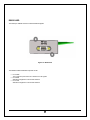
UNPACKING
Care should be taken when removing the packaging in order to avoid damaging the equipment. Remove the outer packaging and inspect for
damage. Shipping brackets are used to attach the UPS and battery cabinets to the skid. Remove these brackets by removing the shipping
bolts attached to the skid and the bolts attached to the cabinet. Use a fork lift to lift up the cabinet from the skid and remove the skid. Lower the
cabinet on its casters. Refer to Figure 1 – Unpacking
Banding strips
Outer packaging
Shipping bracket both sides
Shipping pallet
Figure 1 – Unpacking
1
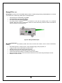
HANDLING
The equipment must be kept upright at all times and handled with care. Damage may be caused if subjected to severe impact. The
UPS and battery cabinet has been fitted with casters to allow ease of installation near the final location. It is recommended that the
UPS and battery cabinets be moved with a pallet jack or fork lift over long distances. The lower side skirts have been intentionally left
off to allow fork access under the UPS or battery cabinets. Refer to Figure 2 – Handling
Figure 2 – Handling
2
STORAGE
When the UPS is not used within seven days of delivery, please pay special attention to the storage requirements.
If the batteries or the equipment is to be stored, they must be kept in a clean, dry environment and away from extremes of
temperature.
STORAGE DATA
Storage temperature range: -4°F (-20°C) to 140°F (60°C); however, batteries should not be exposed to temperature above 77°F
(25°C). Each increment of 15°F (8°C) above 77°F (25°C) reduces the expected battery life by 50%. See battery manufacturer’s
recommendations.
The ideal environmental temperature range is 59° F to 77° F due to the battery life design at 77 F. Each increment of 15 °F
above 77 °F reduces the expected battery life by 50%. See battery manufacturer’s recommendations.
UPS without batteries
-4°F to 140°F (-20°C to 60°C)
Relative humidity from 0% to 95%
UNLESS BATTERY MANUFACTURER’S SPECIFICATION STATES
OTHERWISE
3
Chapter
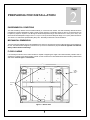
PREPARING FOR INSTALLATION
2
ENVIRONMENTAL CONDITIONS
The UPS and battery cabinets must be installed vertically, on a level and even surface. The UPS and battery cabinets should be
protected from extremes temperatures, water, humidity, and the presence of conductive powder or dust. Do not stack units and do
not place any objects on top of the unit. Although the functional temperature range of the UPS is 32°F to 104°F (0°C to 40°C). The
ideal environmental temperature range is 59°F to 77°F (15°C to 25°C) due to the battery life design at 77°F (25°C). Each increment of
15°F above 77°F reduces the expected battery life by 50%. See battery manufacturer’s recommendations.
MECHANICAL DIMENSIONS
The area must have sufficient space for the installation to be carried out. Access doors must be sufficiently large to permit passage of
the unit. The UPS has been designed to provide front or top access for maintenance purposes. Refer to appendix A for UPS and
Battery Cabinet dimensional drawings.
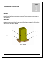
FLOOR LOADING
It is necessary that the floor in the chosen location be capable of supporting the weight of the UPS and battery cabinets. Refer to
appendix A for weights of the UPS and Battery Cabinet. To ease movement over short distances the UPS and battery cabinet is fitted
with casters. Refer to Figure 3 – Bottom View
Cable
Access
Plate
Leveling
Feet
Casters
Figure 3 – Bottom View
4
Chapter
3
UPS INSTALLATION
WARNING:
Dangerous voltages are present within this unit! There are no user-serviceable parts inside. Any repairs or modifications by the user may
result in out-of-warranty repair charges, unsafe electrical conditions, or violation of electrical code. Do not remove the cover. All repairs
should be done by qualified service personnel. Voltages inside the UPS may be lethal. Internal components are powered even when the
power switch is in the OFF position. Even with the battery disconnected and the unit unplugged, energy is stored in high voltage
capacitors and represents a severe shock hazard.
UNLESS MANUFACTURER’S SPECIFICATION STATES OTHERWISE
INSTALLATION DATA
Ambient temperature
32°F to 104°F (0°C to 40°C)
Relative humidity (w/o condensing)
0 – 95%
Max. Altitude (w/o de-rating)
5000 ft a.s.l.
Cable entry
top or bottom
Air inlet
front
Air outlet
top
5
UPS ELECTRICAL CONNECTIONS
In order to gain access to the electrical connections Refer to Figure 5 & 6 – Electrical Terminations, it will be necessary to
remove the protection panel located on the front of the UPS behind the front doors. On the UPS and Transformer
cabinet, power cables can be brought in from the top or bottom through the access plates and routed through the cable
raceway. Refer to Figure 4 – Front View UPS
CABLE RACEWAY PLATE
LOWER PROTECTION PLATE
Figure 4 – Front View UPS
6
UPS ELECTRICAL TERMINATIONS
Figure 5 – UPS Electrical Terminations
Electrical connections
1.
2.
3.
4.
5.
6.
Connect the ground wire to the GND terminal.
For dual input connect the MAIN AC wires to the INPUT A,B,C, and BY-PASS AC wires to BY-PASS A, B ,C, and N
For single input the mains input and bypass will be supplied with jumpers between them.
Connect the output AC wires to the output A,B,C, and N
Connect the optional battery cabinet positive (+) terminal to the positive (+) terminal in the UPS. Connect the optional
battery cabinet positive (-) terminal to the positive (-) terminal in the UPS.
Connect the external battery cabinet ground to the BATT GND terminal.
Note: This UPS may be considered a separately derived source. If this is the case, a jumper will be provided and connected between
ground and the neutral terminations. Therefore, in this configuration an input neutral will not be required. The BY-PASS is phase
rotation sensitive. Clockwise phase rotation is required for the input and bypass. The neutral requirements for the By-Pass input are
solely dependent on the load requirements. If the load requires a Neutral then the Bypass must be supplied with a neutral regardless
of a single input or dual input configuration. This neutral should be sized for three phase unbalanced load conditions. Therefore it is
recommended that the neutral be sized for at least 1.7 times that of the phase conductors. If there is a question concerning this
option, please contact Chloride technical support.
7
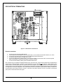
Figure 6 – Input Transformer Cabinet 208/480V
8
Chapter
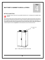
4
BATTERY CABINET INSTALLATION
BATTERY CONNECTIONS
Connections must be carried out only by qualified electricians and in conformity with the applicable safety
standards.
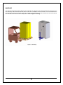
Both the UPS and battery cabinet are similar in appearance. However the battery cabinet houses the backup power required to
provide the energy needed during a power disturbance or outage. The batteries in the battery cabinet have been pre-wired on each
shelf. The battery tray interconnects should only be connected by a factory trained and authorized service representative. It is
recommended that the battery cabinet be located adjacent to the UPS or additional battery cabinets. Battery cabinet cables have
been provided for layouts where the UPS and Battery cabinets are adjacent to each other. Optional extended run-time cabinets can
be added for additional run-times. See Appendix A for recommended protection devices and interconnect cables.
TOP CABLE ACCESS
PLATE
Figure 7 – Battery Cabinet Top Cable Access Plate
9
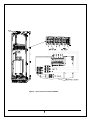
Figure 8 – Battery Cabinet Electrical Connections
10
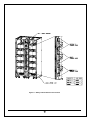
Figure 9 – Multiple Cabinet Connections
As can be seen in Figure 9 – Multiple Cabinet Connections each cabinet will be connected in parallel. The DC connections
between the UPS and battery cabinet must be connected with the most positive of the battery cabinet connected to the positive
termination in the UPS. The most negative of the battery cabinet must be connected to the negative termination of the UPS. See
Figure 6 – UPS Electrical Connections for DC connection within the UPS.
11
Chapter
5
CONTROL PANEL
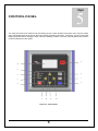
The control panel serves as the interface to the UPS allowing the user to obtain the status of the system and to control as needed.
LED’s (Light Emitting Diode) inform the user about three operating parameters of the UPS (1, 2 & 3 below). The LCD (Liquid Crystal
Display) will provide detail on messages, alarms, values and operating conditions of the UPS. And finally buttons that control the
inverter and shutdown the entire system.
8
13
3
6
2
7
1
5
4
9
12
11
10
Figure 10 – Control Panel
12
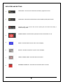
INDICATORS AND BUTTONS
1
ON BATTERY - when this LED is illuminated, the battery supplies the inverter
2
ON BY-PASS - When this LED is illuminated, the load is supplied by the By-pass AC power
3
SUMMARY ALARM - When this LED is solid, the UPS is operating with a fault condition. When blinking, it
indicates a warning condition.
INVERTER ON/OFF - When this button is pushed, the Inverter is turned either on or off
4
5
ENTER - This button allows access to menus on the LCD display
6
ESCAPE - This button escapes from any menu on the LCD display
7
8
CANCEL AUDIBLE ALARM - This button silences current alarm
EQUIPMENT POWER OFF - This button turns off the entire UPS in 0 seconds.
13
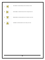
9
LEFT ARROW - This button allows the user to scroll left on the LCD
10
RIGHT ARROW - This button allows the user to scroll right on the LCD
11
DOWN ARROW - This button allows the user to scroll down on the LCD
12
UP ARROW - This button allows the user to scroll up on the LCD
14
Using the Liquid Crystal Display
BY-PASS INPUT
INVERTER
RECTIFIER INPUT
BATTERY
13
LCD Screen – Shows graphical and functional parameters
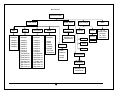
The LCD provides a graphical user interface providing power blocks representing the Rectifier, Battery, Inverter and By-Pass. The
power path will be highlighted providing the user with an understanding of which power blocks are active and that which is supplying
the critical load.
15
Menu Structure
Main Menu Screen
Actual Values
By-Pass
Input
Rect.
Input
UPS Output
Rectifier Alarms
No Faults/
No Warnings
Battery
Values
Displayed
Values
Displayed
Values
Displayed
Values
Displayed
Voltage L1
Voltage L2
Voltage L3
Frequency
Voltage L1
Voltage L2
Voltage L3
Current L1
Current L2
Current L3
Frequency
Total Real Pwr
Real Power L1
Real Power L2
Real Power L3
Total App. Pwr
App. Power L1
App. Power L2
App. Power L3
Voltage L1
Voltage L2
Voltage L3
Current L1
Current L2
Current L3
Frequency
Total Real Pwr
Real Power L1
Real Power L2
Real Power L3
Total App. Pwr
App. Power L1
App. Power L2
App. Power L3
Voltage
Current
Residual
Capacity
Expected
Run Time
Temperature
Message 1 of 3
Mains Failure
DC Bus
Display Settings
Language
English
Dutch
French
Values
Displayed
Voltage
Current
Inverter Alarms
No Faults/
No Warnings
Message 1 of 3
Mains Failure
16
About
Contrast
Contrast
Ver. 1.0
Chloride Power
Protection
Tel. 1-800XXX-XXXX
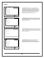
MENUS
MAIN MENU
1
Actual Values
Inverter Alarms
Rectifier Alarms
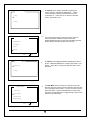
The Main Menu screen’s function is to provide the user the
selection options for viewing various information about the UPS.
This is the highest level for menu. To return to previous screen,
press ESC button. Parameters displayed are: Actual Values,
Inverter Alarms, and Rectifier Alarms Display Settings and About.
Press the ENTER button to select screen. Use the UP and
DOWN arrows to toggle through current screen.
Display Settings
ACTUAL VALUES
2
The Actual Values screen’s function is to allow access to various
parameters at different locations of the UPS. Parameters displayed
are: By-pass Input, Rectifier Input UPS Output, Battery, and DC Bus.
(Shown for By-pass input)
3
The By-pass Input screen displays parameters regarding the Bypass input. Parameters displayed are: Voltage L1, Voltage L2,
Voltage L3, and Frequency. Press down or up arrows to view other
entries. Press ESC to exit.
4
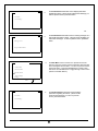
The Actual Values screen’s function is to allow access to
various parameters at different locations of the UPS.
Parameters displayed are: By-pass Input, Rectifier Input UPS
Output, Battery, and DC Bus. (Shown for Rectifier input)
By-pass Input
Rectifier Input
UPS Output
Battery
Press
to select
BY-PASS INPUT
Voltage L1
Voltage L2
ACTUAL VALUES
By-pass Input
Rectifier Input
UPS Output
Battery
Press
to select
17
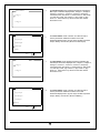
RECT. INPUT
5
Voltage L1
Voltage L2
The Rectifier Input screen displays parameters regarding the
Main Input. Parameters displayed are: Voltage L1, Voltage L2,
Voltage L3, Current L1, Current L2, Current L3, Frequency,
Total Real Power, Real Power L1, Real Power L2, Real Power
L3, Total App. Power, App. Power L1, App. Power L2, App.
Power L3. Press down or up arrows to view other entries.
Press ESC to exit.
.
ACTUAL VALUES
6
The Actual Values screen’s function is to allow access to
various parameters at different locations of the UPS.
Parameters displayed are: By-pass Input, Rectifier Input UPS
Output, Battery, and DC Bus. (Shown for UPS Output)
7
The UPS Output screen displays parameters regarding the
UPS Output. Parameters displayed are: Voltage L1, Voltage L2,
Voltage L3, Current L1, Current L2, Current L3, Frequency,
Total Real Power, Real Power L1, Real Power L2, Real Power
L3, Total App. Power, App. Power L1, App. Power L2, App.
Power L3. Press down or up arrows to view other entries.
Press ESC to exit.
8
The Actual Values screen’s function is to allow access to
various parameters at different locations of the UPS.
Parameters displayed are: By-pass Input, Rectifier Input UPS
Output, Battery, and DC Bus. (Shown for Battery )
By-pass Input
Rectifier Input
UPS Output
Battery
Press
to select
UPS OUTPUT
Voltage L1
Voltage L2
ACTUAL VALUES
By-pass Input
Rectifier Input
UPS Output
Battery
Press
to select
18
BATTERY
9
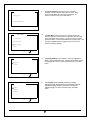
The Battery screen displays parameters regarding the
inverter’s DC bus. Parameters displayed are: Voltage,
Current, Residual Capacity, Expected RUN Time, and
Temperature C. Press down or up arrows to view other
entries. Press ESC to exit.
10
The Actual Values screen’s function is to allow access to
various parameters at different locations of the UPS.
Parameters displayed are: By-pass Input, Rectifier Input UPS
Output, Battery, and DC Bus. (Shown for DC Bus)
11
The DC Bus screen displays parameters regarding the inverter’s
DC bus. Parameters displayed are: Voltage Total, Voltage +, and
Voltage -. Press down or up arrows to view other entries. Press
ESC to exit.
Voltage
Current
ACTUAL VALUES
Rectifier Input
UPS Output
Battery
DC Bus
Press
to select
DC BUS
Voltage Total
Voltage +
12
MAIN MENU
Actual Values
Inverter Alarms
The Main Menu screen’s function is to provide the user the
selection options for viewing various information about the UPS.
This is the highest level for menu. To return to previous screen,
press ESC button. Press the ENTER button to select screen.
Use the UP and DOWN arrows to toggle through current screen.
(Shown for Inverter Alarms)
Rectifier Alarms
Display Settings
Press
to select
19
INVERTER ALARMS
13
No Faults ...
The Inverter Alarms information screen displays parameters
regarding the alarms. (Shown for No Faults and No Warnings) To
return to previous screen, press ESC button.
No Warnings ...
OR INVERTER ALARMS
14
Message 1 of 3
The Inverter Alarms Information screen is showing message 1 of 3
and specific information on alarm. Using the cursor will display any
active alarm messages. To return to previous screen, press ESC
button.
By-pass Mains Failure
MAIN MENU
15
The Main Menu screen’s function is to provide the user the
selection options for viewing various information about the UPS.
This is the highest level for menu. To return to previous screen,
press ESC button. Press the ENTER button to select screen.
Use the UP and DOWN arrows to toggle through current screen.
(Shown for Rectifier Alarms)
16
The Rectifier Alarms information screen displays
parameters regarding the alarms. (Shown for No
Faults and No Warnings) To return to previous
screen, press ESC button.
Actual Values
Inverter Alarms
Rectifier Alarms
.About.. Display
Settings
Press
to select
RECTIFIER ALARMS
No Faults ...
No Warnings ...
20
RECTIFIER ALARMS
17
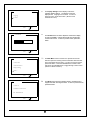
The Rectifier Alarms Information screen is showing
message 1 of 3 and specific information on alarm. Using
the cursor will display any active alarm messages. To
return to previous screen, press ESC button.
18
The Main Menu screen’s function is to provide the user the
selection options for viewing various information about the UPS.
This is the highest level for menu. To return to previous screen,
press ESC button. Press the ENTER button to select screen. Use
the UP and DOWN arrows to toggle through current screen.
(Shown for Display Settings)
19
The Display Settings screen displays a sub menu regarding the
display. Sub menus displayed are: Language and Contrast. (Shown
for Language sub menu.) To return to previous screen, press ESC
button.
20
The Language screen will display a selection of multiple
languages in which will change the text of the display LCD to the
appropriate language desired. Press Down or UP arrow to
desired language. To return to previous screen, press ESC
button.
Message 1 of 3
By-pass Mains Failure
MAIN MENU
Inverter Alarms
Rectifier Alarms
Display Settings
About ...
Press
to select
DISPLAY SETTINGS
Language
Contrast
Press
to select
LANGUAGE
English
Deutsch
Francais
Press
to select
21
DISPLAY SETTINGS
21
Language
Contrast
Press
to select
CONTRAST
22
Press
The Display Settings screen displays sub menus
regarding display settings. The display sub menus
displayed are: Language and Contrast. To return to
previous screen, press ESC button. (Shown for the
Contrast sub menu)
The Contrast screen is used to adjust the contrast of the display
for ease of readability. Use the left and right arrow to adjust the
contrast of the screen. To return to previous screen, press ESC
button.
to select
MAIN MENU
23
Actual Values
Alarm Information
Display Settings
The Main Menu screen’s function is to provide the user the
selection options for viewing various information about the UPS.
This is the highest level for menu. To return to previous screen,
press ESC button. Press the ENTER button to select screen.
Use the UP and DOWN arrows to toggle through current screen.
(Shown for About sub menu)
About ...
Press
to select
24
ABOUT
Version 1.0
The About screen shows the software revision, manufacturer and
support information including the hotline. To return to previous screen,
press ESC button.
Chloride Power Protection
Tel: 1-800-388-4234
Press
to select
22
TABLE OF WARNINGS AND FAULTS
Warnings
Over-temperature inverter
By-pass mains failure
Rectifier mains failure
Load too high
Under-voltage VDC
Overload
False By-pass Phase Sequence
Service By-pass is on
Battery Operation
Battery Rest time Exceeded
Battery Under-Voltage
Commissioning or Test Mode
Battery Switch not Engaged
Ventilator Lifetime Exceeded
Connection to charger lost
Battery Charge Inhibit
Battery Temperature
Output Switch Open
Faults
Over temperature Converter
Internal fault
Incorrect Power Class (Configuration)
Inverter Contactor Defective
Multiple inverter cut off as a result of over current
Over-Voltage VDC
Failure power supply electronics
External Quick Shutdown
DSP Not OK (signal processor defective)
Rectifier Precharge not OK
Inverter Desaturation
Over current cutoff
UPS Out of Tolerance
Output Overload
Backfeed Fault
Bypass Defective
Bypass Hardware Fault
By-pass Overload
Electronic (EEPROM)
UART Communication Fail
Checksum EPROM
Parallel Bypass Fault
Parallel Bypass Fault
DC H/W Control Fault
DC feedback Fault
DC SW Control Fault
Battery Fault
Test LEDs
23
OPERATING MODES
On-Line Operation
CB1, SW1, SW2 and the Battery CB are in the on position and SW3 is in the off position. The loads are supplied by the mains
through the inverter. The batteries are charged by the rectifier as necessary. The Inverter filters mains interruptions, disturbances
and provides a stable, interference-free supply to the load.
Path of Current
The summary alarm LED on the control panel is not illuminated in this mode. If a mains failure occurs while in On-Line operation,
the UPS switches to Battery Operation. The On Battery and Summary Alarm LEDs are illuminated. If an overload condition occurs
at the output, the UPS switches to By-pass operation, if available.
24
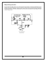
Battery Operation
CB1, SW1, SW2 and the Battery CB are in the on position and SW3 is in the off position. In the event of a mains power failure the
load is automatically transferred to the batteries, without interruption. In this mode, the load is supplied entirely by the batteries, via
the inverter. If the power fails, the UPS indicates a fault condition.
Path of Current
In Battery operation, the On Battery and Summary Alarm LEDs on the control panel are illuminated. If an overload condition occurs
at the output, the UPS switches to By-pass operation, if available.
25
Battery Recharge Operation
CB1, SW1, SW2 and the Battery CB are in the on position and SW3 is in the off position. The UPS returns automatically to On-Line
operation once the mains supply has been restored. The batteries are charged according to the specific battery model provided by
the battery manufacturer’s specifications. Within the battery autonomy period, the UPS provides information regarding the
remaining battery autonomy via the Liquid Crystal Display. At the same time that the batteries are being recharged, the inverter
continues to supply the load.
Path of Current
26
By-pass Operation
CB1, SW1, SW2 and the Battery CB are in the on position and SW3 is in the off position. In this mode, the load is supplied by the
mains through the static switch. This mode of operation does not condition the incoming power. The by-pass further ensures the
supply to the load in the event of an overload condition, manual inverter shut off or the unlikely event that the inverter should fail.
The by-pass is automatically activated in order to ensure that there is no interruption in the load supply.
In By-pass operation, the On By-pass and Summary alarm LEDs on the front panel are illuminated. The UPS returns to online
operation automatically once the fault has been corrected. This will happen only if it is electronically switched and not if the
Path of Current
inverter is manually turned off.
27
Maintenance By-pass Operation
CB1, SW1, SW2 and the Battery CB are in the off position and SW3 is in the on position. The load is supplied directly by the mains
supply. The Maintenance Bypass is used to supply the load during maintenance operations. CB1 and SW1 can be used to supply
power to the UPS for testing or startup without affecting the output. In the Maintenance By-pass Position, all power is removed
except for the fans and power transformers in some models.
Path of Current
Note: In Maintenance By-pass operation, the Display and LED’s do not illuminate.
28
OPERATIONAL PROCEDURES
STARTUP PROCEDURE
1.
2.
3.
4.
5.
6.
7.
8.
With main and By-pass disconnects on wall, CB1, SW1-3 and the Battery Cabinet circuit breaker all off, turn on
the main disconnect and the By-pass disconnect if present.
Turn on SW3 to supply the output with power.
Turn on CB1, SW1, SW2 and the Battery Cabinet circuit breaker.
Check for alarms.
Turn off SW3.
Press and hold for more than three seconds the “INVERTER ON” button on the display.
Check display to insure the rectifier and inverter are on.
The UPS is now supplying the load via the inverter.
*Note: The order is important so that the output is not interrupted.
MAINTENANCE BY-PASS PROCEDURE
1.
2.
Press “INVERTER OFF” for 3 seconds or until the audible alarm is heard and Inverter mimic shows the inverter
section is off.
Switch SW3 on. Turn off CB1, SW1, SW2 and the Battery Cabinet circuit breaker.
Note: The order is important so that the output is not interrupted.
Note: For the 208VAC output UPS (4X2), SW2 can remain on to energize the fans.
Note: For 4X2 units, fans and fuse block remain energized with SW2 on. Use insulated fuse puller for
service.)
SHUTDOWN PROCEDURE
1.
2.
3.
4.
5.
Press “INVERTER OFF” for 3 seconds or until beep is heard and Inverter mimic shows the inverter section is off.
Switch SW3 on and SW2 off.
Turn off CB1 and SW1.
Open Battery Cabinet circuit breakers.
Turn off main disconnect (and By-pass disconnect, if required)
29
Chapter
6
PARALLEL OPTION
The parallel UPS is connected to an AC main power source and contains high current batteries for back up. Therefore
safety precautions must be followed to prevent electrical hazards when operating the parallel UPS system.
Introduction
The CP3150 UPS system can be connected in parallel to increase power capacity or redundancy to the load. Up to 8 units of the
same kVA rating may be configured in parallel.
This feature is an available option and thus can be installed at a later date. Field upgrading should only be installed by a factory
trained and authorized service representative Information contained in this manual includes: Theory of Operation, Planning and
basic electrical installation.
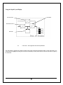
Theory of Operation
The parallel UPS system is automatically regulated by the controllers of the individual UPS modules. The UPS conditions the raw
main power and supplies continuous, clean three-phase power to the critical load/ loads. The UPS will continue to supply clean
power without interruption at the output when the utility power fails. In the event of a main power failure, the UPS will continue to
supply clean power, from the batteries, without interruption.
The UPS modules have cable connections between them to communicate the phase synchronization of the bypass voltages and
shared load current. Phase synchronization is necessary in order to transfer the critical load between the bypass line and inverters.
The transfer from inverters and bypass line functions independently within each individual module in the case of an overload
condition.
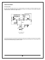
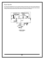
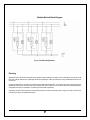
A functional block diagram of a multiple module system is shown in Figure 11 – Parallel configuration.
30
Multiple Module Block Diagram
Fig 11- Parallel Configuration
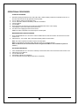
Planning
Special attention must be taken when planning for parallel system installation. The system power cables (input and output) should
be the same length. Differences in cable length of 20% are permitted for cables up to 60ft, but for longer cables differences must not
exceed 10%.
Another important factor to consider is the total size of the parallel UPS configuration. The output power rating of the UPS should be
specified according to the power demand of the protected loads. Some margin of error should be allowed for potential expansion,
and possible inaccuracy in calculations or measuring the actual load requirements.
The battery should be sized according to the desired backup time. Note that the backup time is longer if the load is less than the
nominal power rating of the parallel UPS system.
31
Installation
Input / Output connections
When installing a multiple block parallel system, the input and output connections procedures for each module use the same
terminals as those for a single UPS. For more information refer to Chapter 3 of Owners Manual.
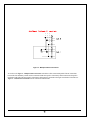
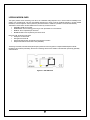
Parallel Communications
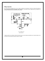
The individual UPS blocks communicate with each other via a 25-conductor cable. The communication cables are shielded and
must be routed separately from the power cables.
Each unit is equipped with a cable channel located in the right front of the UPS. Access to this channel is from the top or bottom
depending on the type of installation. (See chapter 3 figure 5). Route the communication cables through the cable channel to the
terminal blocks X130 and X140. The cable is exiting module from terminal X130 of UPS1 and connected to terminal X140 of the
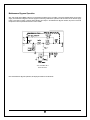
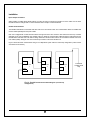
next module (UPS2). See figure 2 for correct closed loop connection of the communication bus.
Figure 2 shows the basic communication wiring for a multiple block system. Note the closed loop configuration. (X130 of UPSn
connected to X140 of UPS1).
X130
X130
UPS
1
X130
UPS
2
X140
X140
X140
Fig 12 - Parallel Communication Block Diagram. (Closed loop
configuration)
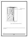
32
UPS
n
Connection
creating closed
loop
Parallel communications
raceway
Figure 13 – Raceway for Parallel Communication Wires
Note: When connecting the communication bus, the shield of the communication cable must be grounded to the UPS on each
end of the cables.
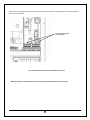
33
.
The Parallel communication terminal blocks (X130 and X140) are located at the upper right front of the UPS, behind the
front door and dead plates.
Parallel Communication
Terminal Blocks
Fig 14- Parallel Communication Terminal Blocks Location
NOTE: Installation of the parallel kit must be completed by Authorized Technical Personnel.
34
Chapter
7
CONNECTIVITY
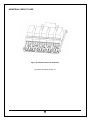
Installation of communication card(s)
The CP3000 series can be equipped with a variety of connectivity options. Five interface slots have been designed to allow
installation of the AS400 card, LIFE 2000 card, R.A.U. card (Remote Alarm Unit), RS232 card and Manage UPS Net adapter card.
These interface slots are located behind the front panel located in the middle right section. See Figure 5 –UPS Electrical
Terminations.
Figure –15 - Interface Slots
35
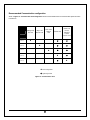
Recommended Communication configuration
Shown in Figure 16 – Communication Card Configuration are the recommendations of those communication options and were
to insert them.
AS400 Card
Remote
Alarm Unit
Card or
Industrial
Contact
Driver Card
{
{
{
{
{
{
Slot 4
z
{
Slot 5
{
z
ManageUPS
Net Card
Slot 1
Slot 2
Mop UPS
RS232 Card
LIFE 2000
Modem
Card
z
z
z
Slot 3
z Preferred position
{ Optional position
Figure 16 - Communication Card
36
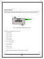
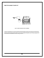
RAU/RLY/DVR CARD
This card allows connection to the Remote Alarm Unit option. It also can be used to drive the Industrial Contact Card as seen in
Figure 17 – RAU (Remote Alarm Unit) or Relay Card or Driver Card. The voltage-free contacts are rated at 30V .5A max.
Figure 17 - RAU (Remote Alarm Unit) or Relay or Driver Card
The RAU/RLY/DVR PCB terminal layout is as follows:
•
Pin 1 is AC Fail *
•
Pin 2 is Low Batt *
•
Pin 3 is On Bypass *
•
Pin 4 is Inv Fail *
•
Pin 5 is Sum Alarm *
•
Pin 6 is Common (Return)
•
Pin 7 is +16V (RAU)
•
Pin 8 is +24V ISO
•
Pin 9 is +24V Ret
•
Pin 10 is +24V Ret
* Note: These outputs can be changed from N/O to N/C directly on the card.
37
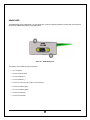
AS400 CARD
The AS400 (Relay) card is equipped with a “D”-type female 9-pin connector comprising voltage-free contacts and conforming to the
requirements of IBM AS/400 and other computing systems.
Figure 18 - AS400 (Relay) card
The interface communication pin layout is as follows
•
Pin 1 is Bypass
•
Pin 2 is Summary Alarm
•
Pin 3 is Shutdown (+)
•
Pin 4 is Shutdown (-)
•
Pin 5 is the common for all contact on internal relays.
•
Pin 6 is Low Battery (N/C)
•
Pin 7 is Low Battery (N/O)
•
Pin 8 is AC Fail (N/C)
•
Pin 9 is AC Fail (N/O)
38
RS232 CARD
The male 9-pos. SUB-D connector contains the RS 232 signals.
Figure 19 - RS232 Card
The interface COM is isolated from all power circuits.
•
•
•
Pin 5 GND
This connection point serves as a reference for all signals.
Pin 2 RXD
Standard configuration of an RS 232 interface.
Pin 3 TXD
Standard configuration of an RS 232 interface.
39
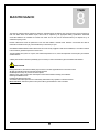
ManageUPSNET CARD
ManageUPSNET (formerly known as the SNMP adapter) includes a complete package allowing CP3000 SERIES to be monitored
and controlled over a network using TCP/IP protocol. The adapter allows:
•
•
•
•
UPS monitoring from an NMS station using SNMP
UPS monitoring from a pc using a Web Browser
SHUTDOWN AND MONITORING SOFTWARE
The primary function of MopUPSPROFESSIONAL for Windows is to shut down the operating system of an unattended
computer, safely, in the event of a power failure. All files are closed and directory pointers are written to disk while the
system is supplied from UPS battery power.
Figure 20 - Manage UPS Net Adapter
MopUPSPROFESSIONAL
for Windows provides this function and offers other features, useful to network administrators,
including:
•
•
•
•
•
•
•
Automated responses to a variety of events – email, messaging, paging, running script files, etc.
Logging of various events and UPS status information to files
Real time viewing of site power and UPS status information
Administrative shutdown for scheduling planned system shutdowns
Control of UPS performance features - set restart to manual, silence alarms.
Remote access and monitoring of UPS connected to remote servers on the network using Named Pipes or TCP/IP
Notification of events via email
40
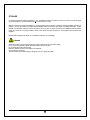
LIFE2000 MODEM CARD
This option provides remote monitoring of the UPS, via a dedicated analog telephone line, to ensure maximum reliability for the
duration of its operational life. The UPS automatically telephones the service center at predefined intervals, to provide detailed
information, which is analyzed in order to predict any short-term failures. In addition it is possible to control the UPS remotely.
Transmission of UPS data to the CHLORIDE service center is by modem and can be:
•
ROUTINE: typically once a week
•
EMERGENCY: when something goes wrong or when parameters are out of tolerance.
•
MANUAL: when requested by the Customer
•
BIDIRECTIONAL: when requested by the service center
During the calls, the service center shall:
•
Identify the connected UPS
•
Recognize the kind of call
•
Request the data stored in the UPS since the previous connection
•
Request information from the UPS on line (selectable).
The storage of the data, and their subsequent analysis, permits the service engineer to compile a detailed report that will be
forwarded to the Customer periodically, with the aim of informing her/him of the condition of the UPS and of preventing potentially
critical situations
Figure 21 - LIFE 2000 Card
41
INDUSTRIAL CONTACT CARD
Figure - 22 Industrial Contact Card and Bracket
The contacts are rated at 120VAC, 2A.
42
REMOTE EQUIPMENT POWER OFF
Figure - 24 Remote Equipment Power Off (REPO)
To wire the external EPO circuit, connect a normally closed (N/C) emergency switch, which opens when activated and is
held open mechanically when operated. Make sure switch is de-activated (closed) before connecting to the outer terminals
of the EPO terminal block (REPO Hi and REPO Low). Remove the jumper wire between the inner terminals (Disable). It is
recommended to use twisted wires for this low voltage connection.
43
Chapter
8
MAINTENANCE
The UPS only requires that the air filters be cleaned on periodical bases and that the area around the UPS is clean and free from
dust and debris. When the batteries expire, these must be replaced by the appropriate battery specifications. Exhausted
accumulator batteries are classified as “harmful toxic waste” and as such, the law demands that they be disposed of by an
authorized recycling center.
Periodic maintenance should be performed on the UPS and batteries. Chloride Power Protection recommends the UPS be
maintenance at least two time per year and batteries up to four times per year.
CHLORIDE POWER PROTECTION Customer Service Center is fully equipped to deal with such batteries, in accordance with the
Law and with the greatest respect for the environment.
The typical battery life cycle is 3 to 5 years, at an ambient temperature of 77 F, but is also dependent on the frequency and duration
of mains failures.
A battery test should be carried out periodically (6 to 12 months) in order to ascertain the general condition of the batteries.
PRECAUTIONS
During maintenance, disconnect the battery trays so that no more than eight batteries are connected in series.
All safety and handling instructions shall be carefully observed.
Qualified personnel may only remove the access panels.
Watches, rings, chains and any other metal objects must be removed before working on the batteries
Rubber gloves must be used.
Insulated tools only must be used.
An insulated mat must be placed in front of the battery cabinet before any operation is carried out thereon.
Never work alone. Ensure the presence of a person able to give assistance in case of accident.
44
STORAGE
For extended storage at ambient temperature < 77°F, the batteries should be charged for 5 hours once every 4 months; at higher
storage temperatures, it is advised that this period be reduced to two months.
Make sure the Power Control Unit Breaker is in the OFF position before continuing. Follow the electrical installation procedure in
Chapter 3. Connect the positive and negative External Battery Cabinet Connections. See chapter 4 for battery information. Switch
the Main Circuit Breaker (CB1) from OFF to ON. After 5 hours, turn OFF the Power Control Unit. For additional external cabinets,
charge for a minimum of 5 hours per battery cabinet. Then remove the UPS connections in the opposite sequence described in
Chapter 3.
Note the date recharging was carried out on the Battery Cabinet or on its packaging.
CLEANING
Switch off the UPS by pressing the Inverter OFF button and disconnect from the mains supply.
Do not use scouring powder or plastic-dissolving solutions to clean the UPS.
Do not allow liquid to get inside the UPS.
Make sure that the air vents on the UPS are not obstructed.
Clean air filters as necessary.
Clean the outside of the UPS housing by wiping with a dry or a slightly damp cloth.
45
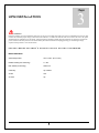
Appendix
INSTALLATION TABLES AND
ILLUSTRATIONS
A
The information in the appendix will provide you with the necessary data to install the UPS and Battery Cabinet.
Following is a list of tables and drawings.
•
Table 1 - Input/ Output Ratings & External Wiring Recommendations
•
Table 2 - Input/Output and Battery Cabinet Wire Terminations for Single Input
•
Table 3 - Input/Output and Battery Cabinet Wire Terminations for Dual Input
•
Table 4 - Full Load Heat Rejection
•
Table 5 - Weight Specifications
•
Illustration A - UPS Dimensions
•
Illustration B - Battery Cabinet Dimensions
•
Illustration C - Battery Cabinet Top Dimensions
46
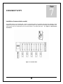
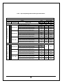
Table 1 - Input/ Output Ratings & External Wiring Recommendations
Model CP3150/150kVA/125kVA
Terminal
Function
Voltage
Configurations
Details
Input/ Output current, Conductor size & Circuit
Breaker rating
Max input current (3Ph, 1 gnd)
Nom input current (3Ph, 1 gnd)
AC Input To UPS Rectifier
208V-208Y/120
Minimum conductor size (number per phase)
Recommended input circuit breaker ratings
Max input current (3Ph, 1 gnd)
Nom input current (3Ph, 1 gnd)
480V-208Y/120
Minimum conductor size (number per phase)
Recommended input circuit breaker ratings
Max input current (3Ph, 1 gnd)
Nom input current (3Ph, 1 gnd)
480V - 480V
Minimum conductor size (number per phase)
AC Input To Bypass (contact Factory)
Recommended input circuit breaker ratings
Nom input current ( 3Ph, 1 gnd)
208V-208Y/120
Minimum conductor size (number per phase)
Recommended input circuit breaker ratings
Nom input current ( 3Ph, 1 gnd)
480V-208Y/120
Minimum conductor size (number per phase)
Recommended input circuit breaker ratings
Nom input current ( 3Ph, 1 Neutral*, 1 gnd)
480V - 480V
Minimum conductor size (number per phase)
Recommended input circuit breaker ratings
47
Units
kVA
kW@ .9PF
A AC
A AC
AWG or
kcmil
3 Pole, A
AC
A AC
A AC
AWG or
kcmil
3 Pole, A
AC
A AC
A AC
AWG or
kcmil
3 Pole, A
AC
A AC
AWG or
kcmil
3 Pole, A
AC
A AC
AWG or
kcmil
3 Pole, A
AC
A AC
AWG or
kcmil
3 Pole, A
AC
Rating for 60Hz
125
150
112
135
542
388
630
458
350(2)
500(2)
600
230
165
700
275
194
1/0(2)
2/0(2)
250
224
161
300
270
190
1(2)
2/0(2)
250
300
N/A
N/A
150
180
4/0
300
200
150
225
180
4/0
300
200
225
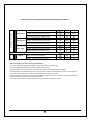
Table 1 Continued - Input/ Output Ratings & External Wiring Recommendations
AC Output to Critical Load
Nom output current ( 3Ph, 1 Neutral, 1 gnd)
208V-208Y/120
Minimum conductor size (number per phase)
Recommended output circuit breaker ratings
Nom output current ( 3Ph, 1 Neutral, 1 gnd)
480V-208Y/120
Minimum conductor size (number per phase)
Recommended output circuit breaker ratings
Nom output current (3Ph, 1 Neutral*, 1 gnd)
480V - 480V
Minimum conductor size (number per phase)
DC Input
Recommended output circuit breaker ratings
480V DC
Battery Current at end of discharge
Minimum conductor size (number per pole)
A AC
AWG or
kcmil
3 Pole, A
AC
A AC
AWG or
kcmil
3 Pole, A
AC
A AC
AWG or
kcmil
3 Pole, A
AC
A DC @
396V
AWG or
kcmil
347
416
250(2)
350(2)
450
347
600
416
250(2)
350(2)
450
150
600
180
4/0
300
200
225
309
370
3/0(2)
4/0(2)
Refer to the following notes when planning your installation.
1) Wire sizes, ratings and circuit breaker sizes are recommended, always consult NEC codes.
2) Consult Local and National electrical codes for acceptable wiring practices.
3) Wires specified are Copper type 75 Deg C / 167 Deg F rated, based on ambient temperature of 104 Deg F.
4) Neutral conductors are considered to be current carrying conductors. Refer to the NEC tables and notes for neutral conductors,
And grounding system requirements. Chloride recommends neutral to be 2x phase conductor.
5) We recommend that the wire size, ratings and circuit breakers be sized to the maximum kVA rating to allow for future up-grades.
6) *AC Input to Bypass requires Neutral if Load requires Neutral.
7) Max currents include Nominal currents plus battery recharge and are not considered continuous.
48
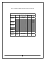
Table 2 – Input/Output and Battery Cabinet Wire Terminations for Single Input
Power Cable Terminations - Single Input
Termination
AC Input
AC Input to
UPS Input
Transformer
AC Output to
Critical Load
Wire Size of Clamp
Termination
Tightening
Torque
In.-lbs
Type
Screw
A
6AWG-350MCM (2)
375
3/8 Hex
B
6AWG-350MCM (2)
375
3/8 Hex
C
6AWG-350MCM (2)
375
A
4AWG-500MCM (2)
375
3/8 Hex
1/2 Hex
B
4AWG-500MCM (2)
375
1/2 Hex
C
4AWG-500MCM (2)
375
1/2 Hex
A
6AWG-350MCM *
375
3/8 Hex
B
6AWG-350MCM *
375
3/8 Hex
C
6AWG-350MCM *
375
3/8 Hex
Terminal
* (2 for 208V Output)
Neutral
Battery
Battery
Cabinet
Ground Only
Customer
Ground
N
6AWG-350MCM (4)
275
5/16 Hex
Positive (+)
6AWG-350MCM (2)
375
3/8 Hex
Negative (-)
6AWG-350MCM (2)
375
3/8 Hex
6AWG-350MCM
375
3/8 Hex
2AWG-600MCM (4)
500
1/2 Hex
Battery
Cabinet
Ground
Ground
(Earth)
49
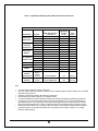
Table 3 – Input/Output and Battery Cabinet Wire Terminations for Dual Input
Power Cable Terminations - Dual Input
N
Positive (+)
Negative (-)
Wire Size of Clamp
Termination
3/0-250MCM (2)
3/0-250MCM (2)
3/0-250MCM (2)
4AWG-500MCM (2)
4AWG-500MCM (2)
4AWG-500MCM (2)
6AWG-350MCM
6AWG-350MCM
6AWG-350MCM
6AWG-350MCM *
6AWG-350MCM *
6AWG-350MCM *
* (2 for 208V Output)
6AWG-350MCM (4)
6AWG-350MCM (2)
6AWG-350MCM (2)
Battery
Cabinet
Ground Only
Battery
Cabinet
Ground
Customer
Ground
Ground
(Earth)
Termination
AC Input to
UPS Rectifier
AC Input to
UPS Input
Transformer
AC Input to
Bypass
AC Output to
Critical Load
Neutral
Battery
Terminal
A
B
C
A
B
C
A
B
C
A
B
C
Tightening
Torque
In.-lbs
275
275
275
375
375
375
375
375
375
375
375
375
Type
Screw
5/16 Hex
5/16 Hex
5/16 Hex
1/2 Hex
1/2 Hex
1/2 Hex
3/8 Hex
3/8 Hex
3/8 Hex
3/8 Hex
3/8 Hex
3/8 Hex
275
375
375
5/16 Hex
3/8 Hex
3/8 Hex
6AWG-350MCM
375
3/8 Hex
2AWG-600MCM (4)
500
1/2 Hex
Note:
•
•
•
•
•
•
•
The cable sizes are defined as minimum cable sizes
Input and output conductors are based on NEC 310-16 for insulated copper conductors rated at 75°C in ambient
temperature of 40°C (104°F).
Grounding conductors are based on NEC 250-95 for copper wire.
UPS input and output cables should be run in separate conduits.
It is recommended that the external cables and protection be selected for the highest possible rating of UPS kVA.
For dual input, connect the mains supply cables to the UPS input terminals A, B, C. Connect the Bypass input to
input terminals A, B, C, N. For single input, connect main input and bypass to the same input source. Connect the
load to UPS output terminals A, B, C, and N. The minimum conductor cross sections apply for maximum currents.
Should there be any variation in the conditions it will be necessary to verify whether the cable dimensions satisfy the
requirements of NEC. In cases where the cables are so long that they cause a drop in voltage of >3%, a larger
dimension shall be selected.
50
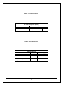
Table 4 – Full Load Heat Rejection
Full Load Heat Rejection (BTU/Hr)
Configuration
Model
2X2
4X2
CP3150-150kVA
56,931
45,556
4X4
34,670
CP3150-125kVA
28,892
47,442
37,963
Table 5 – Weight Specifications
Weight Specifications
CP3150-150kVA/125kVA
Weight (lbs)
480in/480out
2564
480in/208out
3675
208in/208out
3675
"K" Battery Cabinet
3900
Input Transformer Cabinet
1300
51
Floor Loading (lbs)
4 at 641
4 at 919
4 at 919
8 at 488
4 at 325
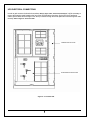
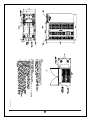
Illustration A
52
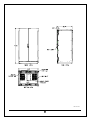
Illustration B
53
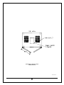
BATTERY CABINET TOP
DIMENSIONS
Illustration C
54
For a number of years CHLORIDE POWER PROTECTION has been committed to a policy of Total Quality and today devotes a
great deal of resources and energy to providing the best possible after-sales service.
Therefore, we value any suggestion you might make and consider it an inspiration for our continued improvement.
We thank you in advance for any such suggestions that may be forwarded to the addresses listed in the last page.
This document is for information only. It is the policy of this company that its products are continually improved therefore
CHLORIDE POWER PROTECTION reserves the right to alter any or all of the information contained herein without prior notice.
CHLORIDE
POWER PROTECTION
28430 North Ballard Drive
Lake Forest, IL 60045
Phone: 1-800-239-2257
Fax: 1-800-833-6829
www.chlorideups.com
55