1
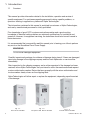
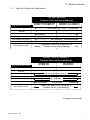
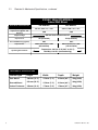
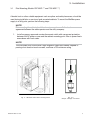
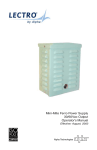
MiniMax Power Supply
Installation and Operation Manual
60V/9A and 60V/15A Output Models
Effective: November, 2003
®
Alpha Technologies
Power
Alpha Technologies.
Protecting The Power in Communications.
MiniMax Power Supply
Installation and Operation Manual
60V/9A and 60V/15A Output Models
164201241-001 Rev. C0
© 2003 Alpha Technologies
NOTE
Photographs and drawings contained in this manual are for illustrative purposes only.
These photographs and drawings may not exactly match your installation.
NOTE
Review the drawings and illustrations contained in this manual before proceeding.
If there are questions regarding the safe operation of this powering system, please
contact Alpha Technologies or your nearest Alpha representative.
NOTE
Alpha denies responsibility for any damage or injury involving its enclosures, power
supplies, generators, batteries, or other hardware when used for an unintended
purpose, installed or operated in an unapproved manner, or improperly maintained.
WARRANTY NOTICE
Alpha Technologies, Inc., provides a LIMITED WARRANTY covering the
performance of all Alpha’s CATV and Broadband products. The terms and
conditions of the LIMITED WARRANTY STATEMENT are contained in a separate
written LIMITED WARRANTY STATEMENT. If there are any warranty claims, the
purchaser (or purchaser’s representative) must follow the LIMITED WARRANTY
guidelines, described in the applicable LIMITED WARRANTY STATEMENT.
Contacting Alpha Technologies:
For general product information and customer service
1-800-863-3930
(7:00 AM to 5:00 PM Pacific Time )
For complete technical support
1-800-863-3364
(7:00 AM to 5:00 PM Pacific Time, or 24/7 emergency support)
164201241-001 Rev. C0
3
MiniMax Power Supply
Installation and Operation Manual
Table of Contents
Warnings & Cautions ............................................................................................ 5
1. Introduction ....................................................................................................... 6
1.1
Overview .............................................................................................. 6
2. Specifications ................................................................................................... 7
2.1
Electrical & Mechanical Specifications ................................................ 8
3. Installation ........................................................................................................ 9
3.1
Pole Mounting ...................................................................................... 9
3.2
Ground Mounting................................................................................ 11
3.3
Electrical Connections for Pole and ground Mounting........................ 13
3.4
Wall Mounting and Electrical Connection ........................................... 15
4. Operation ........................................................................................................ 17
4.1
Initial Turn Up ..................................................................................... 17
5. Maintenance ................................................................................................... 17
List of Figures
4
Fig. 1-1
Fig. 1-2
Fig. 1-3
60VAC/15A, Pole/Wall Mount MiniMax ................................................ 6
60VAC/9A, Pole/Wall Mount MiniMax .................................................. 6
60VAC/15A, Ground Mount MiniMax.................................................... 6
Fig. 3-1
Fig. 3-2
Fig. 3-3
Fig. 3-4
Fig. 3-5
Fig. 3-6
Fig. 3-7
MiniMax Pole Mount Arrangement ....................................................... 9
Output Voltage Connector .................................................................... 9
MiniMax Concrete Pad Dimensions ................................................... 11
Attaching the MiniMax Cabinet to the Pad .......................................... 12
Receptacle Connections .................................................................... 13
Service Cable Routing ....................................................................... 15
Terminal Block Connections............................................................... 16
164201241-001 Rev. C0
WARNINGS & CAUTIONS
A “Warning” identifies conditions and actions that pose a hazard to the user.
A “Caution” identifies conditions and actions that may damage the power supply or associated
equipment.
WARNING
This power supply and its associated hardware (enclosure, cabling) may contain equipment(s), or
parts which have accessible hazardous voltage or currents.
To avoid injury:
• This power supply and its associated hardware must be serviced by authorized personnel only.
• Verify AC line power is de-energized prior to installation or service.
• Remove all conductive jewelry or personal equipment prior to servicing equipment, parts, connectors,
wiring, or batteries.
• Read and follow all installation, equipment grounding, usage, and service instructions included in this
manual.
CAUTION
This Power Supply may contain equipment(s) or part(s) that may be damaged or cause damage to other
equipment if improperly used.
To avoid damage:
• An agency-approved service disconnect switch with overcurrent protection must be provided by the
installer. It must be connected between the utility power source and the power supply. Subject to local
codes, the service disconnect switch must be an outdoor, NEMA 3R enclosure, rated 120/240V, with a
non-interrupted termination. The disconnect shall be a circuit breaker type provided with a dual 15A
circuit breaker for the main and neutral input lines. Due to the ferroresonant transformer, the circuit
breaker should be a high inrush magnetic type able to withstand short duration inrush currents.
• Overcurrent protection and disconnecting means for the AC output are to be supplied by the installer as
required by local codes.
• Use #16AWG (1,28mm2 ) minimum Copper, 75C, for all utility input wiring.
• Prior to installation, verify that the output voltage from the enclosure or its equipment match the voltage
requirements of the connected equipment (load).
• Verify the enclosure which houses the power supply has sufficient ventilation to maintain the power
supply in its specified operating temperature range (-40°C to +55°C).
• Do not operate the power supply in an environment containing corrosive or conductive gas, vapor,
liquid, or dust.
• When servicing the power supply, use on specified replacement parts.
• Servicing is to be performed only by authorized personnel.
164201241-001 Rev. C0
5
1. Introduction
1.1
Overview
This manual provides information related to the installation, operation and service of
specific equipment. For assistance regarding personnel training, specific problems, or
questions relating to applications, please call Alpha Technologies.
The information contained in this manual is restricted to customers of Alpha Technologies,
and use by unauthorized personnel is strictly prohibited.
Prior knowledge of good CATV system construction practice and a good working
knowledge of electrical safety practices are minimum qualifications for installation and
operation. However, for equipment servicing, the technician should also be well versed in
basic electronics.
It is recommended that you carefully read this manual prior to leaving your office to perform
any work on the Broadband Ferro Power Supply.
WARNING
Do not install damaged equipment.
Carefully inspect each package for evidence of damage during transit. If items are damaged,
report any damage to the shipping company and the local Alpha sales or service office
immediately.
After inspection by the shipping company and a written appraisal of the damage has been
received, inform Alpha Technologies that you intend to return the merchandise and request
a return authorization number. Return the items promptly with the return authorization and
invoice number clearly shown on the shipping label.
Alpha Technologies will either repair or replace the equipment, depending upon the extent
of the damage.
Fig. 1-1
Pole Mount MiniMax
6
Fig. 1-2
European Wall Mount MiniMax
Fig. 1-3
Ground Mount MiniMax
164201241-001 Rev. C0
2. Specifications
2.1
Electrical & Mechanical Specifications
120 VAC MODELS
Outdoor Pole and Ground Mount
ELECTRICAL SPECIFICATIONS
PSF-MXP-AXX, PSF-MXG-AXX
PCS-MXP-111, PCS-MXG-111
120 Vac, 60Hz (+15% / -20%)
Input Voltage
Input Current (@ 60V, 15A
Nominal)
5A
9A
60Vrms Quasi-square wave ±3%
Output Voltage
Output Current
Operating Environment
9A (maximum)
15A (maximum)
88% (minimum)
Full Load Efficiency (typical)
Output Pow er
PCS-MXP-113, PCS-MXG-113
PCS-MXP-114, PCS-MXG-114
900VA max. @ 60V (15A resistive)
540VA max. @ 60V (9A resistive)
Temperature: -40°C to 55°C (-40°F to 131°F)
Humidity: 0 to 95% (noncondensing)
220VAC, 230VAC MODELS
Outdoor Pole and Ground Mount
ELECTRICAL SPECIFICATIONS
PSF-MXP-CXX
PSF-MXG-CXX
PSF-MXP-DXX
PSF-MXG-DXX
Input Voltage
220 Vac, 60Hz +15% / -20%
230 Vac 50Hz
Input Current (@ 60V, 15A
Nominal)
4.8A
4.8A Max.
Output Voltage
Output Current
Full Load Efficiency (typical)
Output Pow er
Operating Environment
60Vrms Quasi-square wave ±3%
15A (maximum)
15A (maximum)
88% (minimum)
900VA maximum @ 60V
(15A resistive)
Temperature: -40°C to 55°C (-40°F to 131°F)
Humidity: 0 to 95% (noncondensing)
Continued on next page.
164201241-001 Rev. C0
7
2.1
Electrical & Mechanical Specifications, continued
230VAC, 50Hz (CE) MODELS
Indoor/Wall Mount
ELECTRICAL SPECIFICATIONS
PSF-W00-D09
PSF-W00-D15
Input Voltage
230 Vac, 50Hz +15% / -20%
230 Vac, 50Hz +15% / -20%
Input Current (@ 60V, 15A
Nominal)
3.0A
4.8A
60Vrms Quasi-square wave ±3%
Output Voltage
Output Current
9A (maximum)
Full Load Efficiency (typical)
90%
Output Power
540VA maximum @ 60V
(9A resistive)
Operating Environment
15A (maximum)
88%
900VA maximum @ 60V
(15A resistive)
Temperature: -40°C to 55°C (-40°F to 131°F)
Humidity: 0 to 95% (noncondensing)
MECHANICAL SPECIFICATIONS
8
Cabinet type
Height
Width
Depth
Weight
Pole Mount
386mm (15.2")
197mm (7.3")
213mm (8.4")
15kg (33lb)
Ground Mount
561mm (22.2")
197mm (7.3")
213mm (8.4")
16kg (35lb)
Indoor Enclosure
350mm (13.8")
179mm (7.0")
170mm (6.7")
16kg (35lb)
164201241-001 Rev. C0
3. Installation
Pole Mounting (Models PSF-MXP-*** and PCS-MXP-***)
3.1
A bucket truck or other suitable equipment such as spikes and safety harnesses, should be
used during installation or service of pole-mounted cabinets. To mount the MiniMax power
supply to a utility pole, perform the following steps:
NOTE
Pole mounting the cabinet should be done in accordance with the local
agreement between the cable operator and the utility company.
1.
Install an agency approved service disconnect switch with overcurrent protection
between the AC power source and the cabinet mounting point. Wire to power line in
accordance with local codes.
NOTE
The disconnect box should have a high-magnetic type circuit breaker, capable of
passing short duration inrush currents, and have a 15A minimum rating.
Fig. 3-1 MiniMax Pole Mount Arrangement
164201241-001 Rev. C0
Fig. 3-2
Output Voltage Connector
9
3. Installation
Pole Mounting (Models PSF-MXP-*** and PCS-MXP-***), continued
3.1
2.
Remove all equipment, hardware, and options from the cabinet and store in a
secure location for future use.
3.
Remove the U-shaped mounting bracket from the cabinet rear panel.
4.
Use the bracket as a template to mark mounting holes at the desired mounting
location. If possible, position the cabinet so the front panel is easily accessible.
5.
Drill 11/16" holes in the pole at the marked locations.
6.
Attach the mounting bracket to the pole using customer-supplied hardware. Tighten
securely.
7.
Optional metal band mounting for metal/cement poles: insert the customer-supplied
metal bands or straps through the band slots on the mounting bracket. Tighten the
bands securely.
8.
Raise the cabinet and set into place on the bracket. Attach the cabinet using the
hardware removed in Step 2. Tighten the bolts securely.
9.
Confirm availability of a suitable ground rod next to the power pole. If required, drive
a rod according to local codes.
10. Continue to “Electrical Connections”.
10
164201241-001 Rev. C0
3. Installation
Ground Mounting (Models PSF-MXG-*** and PCS-MXG-***)
3.2
Although ground mounting the power supply can be accomplished by several methods, the
following procedure is recommended.
1.
2.
Select an appropriate site. Remove the turf and level an area of approximately 36" x
36".
In accordance with local codes, install the disconnect box near the AC power
source.
NOTE
The disconnect box should have a high-magnetic type circuit breaker, capable
of passing short duration inrush currents, and have a 15A minimum rating.
3.
From the disconnect, install conduit to the power supply site and turn a stub up to
extend above ground level. Drive a suitable ground rod according to local codes.
Install appropriate size conduit for the output connections and turn a stub up to
extend flush with the pad surface cast into the concrete. Ensure the conduit
locations correspond with the appropriate cabinet connections.
4.
Use 1" x 4" lumber to construct a form for the cement pad (see figure for
dimensions). Anchor the form securely to the ground.
NOTE
It is recommended that the cement pad dimensions extend beyond the ground skirt
by 3" in front, and 3-5" in the back.
7.00"
1.50"
4.00"
7.50"
3.75"
Fig. 3-3 MiniMax Concrete Pad Dimensions
164201241-001 Rev. C0
11
3. Installation
Ground Mounting (Models PSF-MXG-*** and PCS-MXG-***), continued
3.2
5.
Attach the ground mounting brackets from the supplied kit to the ground skirt using
the 5/16-18 x 3/4” screws and the 5/16"-18 nuts.
6.
Make a template from sheet metal or wood indicating the position of the ground
mounting bracket mounting holes. Drill out the four holes in the template and insert
two customer-supplied 5/8" x 4" bolts. The head of the bolts will be embedded into
the concrete pad when installation is complete. Leave sufficient thread above the
pad for securing the ground skirt.
7.
Center and secure template (with bolts in position) over the form. Be sure the
conduit stub-ups for the AC input and the ground rod are positioned at the desired
locations just outside the ground skirt. Optional: the conduit stub-ups may pass
through the cement pad.
8.
Pour, level, and finish the concrete to the bottom of the template. Allow to cure for 24
hours.
9.
Attach the ground skirt to power supply cabinet. Align skirt inside the bottom lip of
the cabinet and secure with the 10-32 x 3/8" screws from the parts kit.
10. Attach the power supply to the concrete pad with customer-supplied 5/8" nuts
through the ground mounting brackets. Tighten all hardware securely.
11. Continue to “Electrical Connections”
Rear Cover
Mounting
Brackets
Concrete Pad
Fig. 3-4 Attaching the MiniMax Cabinet to the Pad
12
164201241-001 Rev. C0
3. Installation
3.3
Electrical Connections for Pole and Ground Mounts
WARNING
Verify the utility disconnect is off and that no conductors are
energized before proceeding.
1.
Open the housing cover and place a screwdriver blade in the small notch at the top
of the housing to hold the cover in place.
2.
Install a liquid tight conduit to the fitting on the cabinet bottom and pull the AC
primary wiring in to the cabinet housing.
3.
Remove the necessary receptacle knockout and install the receptacle provided as
shown. Connect the AC high input to the receptacle terminal labeled MAIN, the AC
neutral input to the receptacle labeled N, and the utility protective ground (green/
yellow) to the green receptacle terminal. Tighten the screw to a torque of 20 lb-in.
Fig. 3-5 Receptacle Connections
4.
Position all wiring neatly in the receptacle box and install the receptacle and cover.
5.
Using the output wire harness (green and yellow wires with power lock connectors,
a seizure clamp, and O-ring), and cable adapter from the parts kit, install the cable
adapter and ground wire. Insert the cable adapter from the outside of the cabinet
into the paint-masked hole, along with the supplied cable feed guard bracket for
ground mount installation. Use the locknut to secure the adapter and the large Oring to the cabinet. Tighten securely.
6. Prepare the incoming coaxial cable used for the distribution of power (including
external fittings not supplied by Alpha).
7. Loosen the brass seizure screw output fitting to accommodate the center pin
(“stinger”) of the cable connector.
NOTE
The center conductor may also be trimmed to allow for a flush fit. The length of the
center conductor must be 1.25” from the end to the center of the O-Ring.
164201241-001 Rev. C0
13
3. Installation
3.3
Electrical Connections for Pole and Ground Mounts, continued
1.25”
Brass Seizure Screw
8. Screw the cable connector into the output port (large hex nut fitting) located on the
baseplate of the APC2. Make sure that the center pin extends far enough into the
fitting so that the seizure assembly can be secured.
Hex-nut Fitting
9. Tighten the brass seizure screw on the cable “stinger” or center conductor. If a
connection is left loose, arcing and possible damage to the center conductor could
occur. During routine maintenance, always check the seizure screw assembly to
ensure that it is tight.
10. Connect an unbroken 6 AWG soft-drawn copper ground wire between the lug
provided on the back of the cabinet and a ground rod for lightning protection. Use a
ground rod clamp of the proper type, above or below grade.
NOTE
If local codes require bonding to utility ground, a separate ground rod and
vertical should be provided, then the two verticals should be bonded at the
bottom of the pole.
11. If this is a ground mount installation, attach and secure the ground skirt front with
the screws provided.
12. Plug the power cord into the receptacle box.
13. Install any optional equipment at this time, referring to the instructions supplied with
the option.
14. Remove the screwdriver used as a lid stop and close the lid, securing it with the
single screw at the bottom
14
164201241-001 Rev. C0
3. Installation
Wall Mounting and Electrical Connection (Models PSF-W00-D**, PSF-W00-D09, and
PSF-W00-D15)
3.4
NOTE
The MiniMax non-standby power supply must be installed in accordance with local
building codes to prevent damage to the mounting structure and the unit itself.
1.
Install an agency-approved service disconnect switch with overcurrent protection,
between the AC power source and the cabinet mounting point. Wire to power line
in accordance with local codes.
2.
Power to the MiniMax is supplied with a round service cable such as UL type SJT16/14-3 (3 x 1mm²) conductor (max. dia. 11.5mm/0.47") from the service
disconnects to the inside of the unit. Allow enough length for an adequate service
loop.
3.
If mounting to sheet rock or paneling, find the wall studs for secure mounting.
4.
Mount to wall with appropriate hardware, such as (6) M5 x 25mm wood screws.
5.
Route service (mains) cable in through the bottom of the unit via the black nylon
fitting. After cable is inserted to the proper position, twist fitting knob in the
clockwise direction to tighten on cable.
Coax Connector
Nylon Cord Fitting
Service (Mains) Cable
Fig. 3-6 Service Cable Routing
164201241-001 Rev. C0
15
3. Installation
Wall Mounting and Electrical Connection (Models PSF-W00-D**, PSF-W00-D09, and
PSF-W00-D15), continued
3.4
6.
Connect the electrical service to the to terminal block located inside the unit, as
shown in figure 3-7.
N/C
60 VAC Out
N
L
Fig. 3-7 Terminal Block Connections
16
7.
Connect the CATV coax cable to the type G2 connector on bottom of the enclosure.
(Refer to figure 3-2.)
8.
Test installation according to requirements. When power is applied to mains, and
appropriate cable load is connected, verify that output voltage across coax cable
connector is 60V ± 3%.
164201241-001 Rev. C0
4. Operation
4.1
Initial Turn Up
1.
Turn the utility disconnect ON. The green lamp should light, indicating power output.
Power will be applied to the cable plant at this time.
2.
If desired, the output voltage can be checked at the cable center conductor seizure
clamp and the cable ground, using a true RMS AC voltmeter.
NOTE
If operating from an alternative AC power source such as a generator, the generator
must have a high-quality regulated output consistent with a minimum power rating
that is 50% higher (measured in Watts) than the MiniMax power rating.
5. Maintenance
Once the initial installation and testing are complete, operation is automatic. When the green
indicator lamp is on, the system is operating from the power line. Proper operation and long
system life can be best assured by a regular performance of the following maintenance
steps.
1.
Before opening the housing, inspect it for external damage or tampering, including
the grounding circuit.
2.
Unlock and open the housing.
3.
Inspect the connectors and cable for damage or corrosion.
4.
Close and re-lock the housing.
164201241-001 Rev. C0
17
Power
www.alpha.com
Protecting The Power in Communications.
Alpha Technologies Ltd.
4084 McConnell Court
Burnaby, BC, V5A 3N7
CANADA
Tel: (604) 430-1476
Fax: (604) 430-8908
Alpha Technologies
Europe Ltd.
Cartel Business Estate
Edinburgh Way
Harlow,EssexCM202TT
UNITEDKINGDOM
Tel: +44-1279-422110
Fax: +44-1279-423355
Alpha Technologies
Hansastrasse 8
D-91126 Schwabach
GERMANY
Tel: +49-9122-79889-0
Fax: +49-9122-79889-21
Alphatec
339 St. Andrews Street
Suite 101
AndreaChambers
Limassol, Cyprus
CYPRUS
Tel: +357-25-375675
Fax: +357-25-359595
Alpha Technologies
Unit R5-R7 Regents Park Estate
Corner Park Rd and Prince’s Rd East
Regents Park, NSW 2143
AUSTRALIA
Tel: +61-2-9722-3320
Fax: +61-2-9722-3321
Due to continuing product improvements, Alpha reserves the right to change specifications without notice.
Copyright © 2003 Alpha Technologies, Inc. All rights reserved. Alpha is a registered trademark of Alpha Technologies.
164201241-001 Rev. C0