1
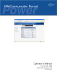
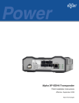
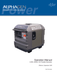
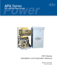
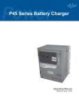
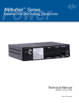
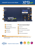
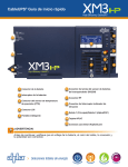
APX100W
APX
- 100W
Non-standby Power Supply
Installation and Operation Manual
APX - 100W Non-standby Power Supply
Effective: April 2006
Alpha Technologies
Alpha Technologies
Power
®
APX - 100W
Non-standby Power Supply
016-538-B0-002, Rev B
Effective Date: April 2006
Copyright © 2006
Alpha Technologies, Inc.
member of the Alpha Group
NOTE:
Photographs contained in this manual are for illustrative purposes only. These photographs may not match
your installation.
NOTE:
Operator is cautioned to review the drawings and illustrations contained in this manual before proceeding. If
there are questions regarding the safe operation of this powering system, please contact Alpha Technologies
or your nearest Alpha representative.
NOTE:
Alpha shall not be held liable for any damage or injury involving its enclosures, power supplies, generators,
batteries, or other hardware if used or operated in any manner or subject to any condition not consistent with
its intended purpose, or is installed or operated in an unapproved manner, or improperly maintained.
Contacting Alpha Technologies: www.alpha.com
or
For general product information and customer service (7 AM to 5 PM, Pacific Time), call
1-800-863-3930,
For complete technical support, call
1-800-863-3364
7 AM to 5 PM, Pacific Time or 24/7 emergency support
Table of Contents
Safety Notes .......................................................................................................................... 6
1.0
2.0
Introduction ................................................................................................................. 7
1.1
Operating Principle .......................................................................................... 8
1.2
Features ........................................................................................................... 9
Installation................................................................................................................. 10
2.1
Pole-mount Installations................................................................................. 10
2.2
2.1.1 Wooden Pole Procedure ..................................................................... 10
2.1.2 Steel or Concrete Pole Procedure .......................................................11
Connecting the APX-100W ........................................................................... 12
2.2.1 Utility Power Connection ..................................................................... 12
2.2.2 External Service Disconnect ............................................................... 13
3.0
Operation .................................................................................................................. 14
3.1
4.0
5.0
4
Start-Up and Test ........................................................................................... 14
Troubleshooting and Repair ..................................................................................... 15
4.1
Troubleshooting ............................................................................................ 15
4.2
Repair Instructions ......................................................................................... 15
4.3
Parts and Ordering Information...................................................................... 15
4.4
Schematic / Block Diagram ............................................................................ 16
Specifications............................................................................................................ 17
016-538-B0-002 Rev. B
List of Figures
Fig. 1-1, APX-100W Non-standby Power Supply ................................................................ 7
Fig. 1-2, APX-100W , Cover Open ....................................................................................... 7
Fig. 1-3, Ferroresonant ‘Tank’ Circuit and Resulting Output Waveform ............................... 8
Fig. 1-4, APX-100W Features.............................................................................................. 9
Fig. 2-1, Mounting Bracket for Wooden Pole...................................................................... 10
Fig, 2-2, Mounting Bracket for Steel or Concrete Pole ........................................................11
Fig, 2-3, APX-100W Base.................................................................................................. 12
Fig, 2-4, Input Terminal Block ............................................................................................. 12
Fig. 2-5, Input Power Cable Clamp .................................................................................... 12
Fig, 2-6, Typical 240VAC Service Entrance Wiring ............................................................ 13
Fig. 4-1, APX-100W Schematic .......................................................................................... 16
List of Tables
Table 2-1, Alpha Part Numbers for Square D Breakers ...................................................... 13
Table 4-1, Troubleshooting Guide....................................................................................... 15
Table 4-2, Replacement Parts ............................................................................................ 15
Table 5-1, APX-100W Specifications ................................................................................ 17
016-538-B0-002 Rev. B
5
Safety Notes
Review the drawings and illustrations contained in this manual before proceeding. If there are any
questions regarding the safe installation or operation of the system, contact Alpha Technologies or the
nearest Alpha representative. Save this document for future reference.
To reduce the risk of injury or death, and to ensure the continued safe operation of this product, the
following symbols have been placed throughout this manual. Where these symbols appear, use extra
care and attention.
ATTENTION:
The use of ATTENTION indicates specific regulatory/code requirements that may affect the placement
of equipment and installation procedures.
NOTE:
A NOTE provides additional information to help complete a specific task or procedure.
CAUTION!
The use of CAUTION indicates safety information intended to PREVENT DAMAGE to
material or equipment.
WARNING!
A WARNING presents safety information to PREVENT INJURY OR DEATH to the
technician or user.
6
016-538-B0-002 Rev. B
1.0
Introduction
The Alpha APX-100W Non-standby Power Supply provides conditioned power to signal amplifiers
in cable television and broadband distribution systems. The transformer is mounted directly to the
chassis, and supplies the load with current-limited, regulated AC power, that is free from spikes,
surges and other forms of power line transients. Once AC power enters the module, it is converted to
a “quasi” square wave and regulated at the required output voltage.
The APX-100W is extremely efficient, with a typical efficiency rating of 90%, and is designed to be
either pole or wall-mounted. This product, along with the entire line of Alpha power products, is one
of the most rugged, reliable, and versatile power supplies available. Alpha Technologies, recognized
as an international market leader in the field of backup power, offers complete technical support
and prompt, reliable service to ensure that your power supply continues to provide you with years of
trouble-free operation.
Fig. 1-1, APX-100W Non-standby Power Supply
Fig. 1-2, APX-100W (cover open)
016-538-B0-002 Rev. B
7
1.0
Introduction, continued
1.1
Operating Principle
The base APX-100W unit contains a ferroresonant transformer, resonant circuit capacitor,
and an input/output terminal block.
The APX-100W uses ferroresonant transformer technology to provide line conditioning and
voltage regulation. The primary and secondary windings of the transformer are physically
isolated from each other by a large steel core which greatly reduces the capacitive coupling
of spikes and noise to the secondary winding. This provides a regulated, current-limited
output with excellent isolation and noise attenuation: 120dB in common mode; and 60dB in
transverse mode.
An oil-filled resonant capacitor is connected to the resonant (secondary) winding of
the transformer forming a tank circuit. This provides the resonant circuit function which
contributes to the voltage regulation of the supply. The advantage of this type of transformer/
capacitor design is the ability of the ferroresonant transformer to regulate its output voltage
over a wide range of input voltages and output loading. Typical output voltages may vary +
3% to 5%, with input voltage variations of + 15% of nominal line voltage, and output loading
of 20% to 100%. This tight regulation is advantageous in cable television applications as the
active devices are protected from dangerous voltage fluctuations.
Another unique feature of the ferroresonant transformer is its ability to provide current limiting
in the event of a short circuit. This effect is called foldback. The transformer’s output current
can typically reach 150% of the nameplate output current rating for a short period of time
without damage to the transformer. When the transformer reaches the saturation point, the
output current will decrease (foldback on itself) to a minimum value, and thereby provide
current limiting. Designs based on a ferroresonant transformer are extremely rugged and
reliable, and offer many years of trouble-free operation.
NOTE:
A true RMS voltmeter must be used to correctly measure the output voltage of the APX-100W .
T1
Ferroresonant Transformer and
AC Capacitor
Noisy Input Waveform
C1
Clean Output Waveform
Fig. 1-3, Ferroresonant ‘Tank’ Circuit and Resulting Output Waveform
8
016-538-B0-002 Rev. B
1.0
Introduction, continued
1.2
APX-100W Features
660 V Oil
Capacitor
Input/Output
110VA
Ferroresonant
Transformer
Input Circuit Breaker
(Self Resetting)
Ground Lug
Utility Input
Fig. 1-4, APX-100W Features
016-538-B0-002 Rev. B
9
2.0 Installation
2.1
Pole-mount Installations
You can mount the APX-100W on a wooden, steel or concrete pole. If installed on a wooden
pole, the mounting bolts must completely penetrate the pole and be secured from the
back with a large washer and nut. If installed on a steel or concrete pole, you must use an
approved mounting strap. In the majority of cases, local codes specify a minimum height
requirement when mounting the enclosure. Verify height restrictions before you proceed.
NOTE:
Poles are typically the property of your local utility. Before you install an enclosure, have your local utility
approve the location and your chosen mounting method.
2.1.1 Wooden Pole Procedure
Materials required:
•
5/8" diameter machine bolt (UNC thread); SAE (Grade 5 or better), length to suit
pole
•
Two 5/8" diameter zinc-plated flat washers
•
5/8" diameter hex net (UNC thread)
Tools required:
•
Auger or drill for boring a 3/4" diameter hole through wooden pole
•
Mallet or hammer
•
Assorted sockets or wrenches
Procedure:
1. Unpack the unit and the galvanized bracket.
2. Mark the position for the mounting bracket on the utility pole.
3. Drill a 3/4” hole completely through the pole. Secure the bracket with a 5/8"
machine bolt, washer and nut.
4. From the back of the enclosure back out the 3/8"-16" bolt sufficiently to mount
the unit to the bracket.
5. Position the unit on the mounting bracket. It may be necessary to slightly rock
the unit and pull downward to properly seat it on the bracket. Tighten the bolt
loosened in step 4.
Fig. 2-1, Mounting Bracket for Wooden Pole
10
016-538-B0-002 Rev. B
2.0
Installation, continued
2.1
Pole-mount Installations, continued
Fig. 2-2, Mounting Bracket for Steel or Concrete Pole
2.1.2 Steel or Concrete Pole Procedure
Materials required:
Customer-supplied stainless, galvanized, or equivalent pole straps to secure the
galvanized mounting brackets to the pole.
Tools required:
Assorted sockets or wrenches
Procedure:
1. Unpack both the unit and galvanized brackets.
2. Position the mounting bracket on the pole and secure it using your pole straps.
3. From the back of the enclosure back out the 3/8"-16" bolt sufficiently to mount
the unit to the bracket.
4. Lift the unit onto the upper mounting bracket and pull downward to properly seat.
Tighten the bolt loosened in step 3.
016-538-B0-002 Rev. B
11
2.0
Installation, continued
2.2
Connecting the APX-100W
2.2.1
Utility Power Connection
Utility power enters the enclosure through a 0.875" diameter opening at the base of
the APX-100W enclosure. The enclosure accepts a standard one inch conduit fitting.
Ground Lug
Utility Input
Fig. 2-3, APX-100W Base
Tools required:
•
1/2" flat-blade screwdriver
•
1/8" flat-blade screwdriver
From the External service disconnect, the AC utility wiring connects to the Input
Terminal Block located internally at the base of the APX-100W enclosure.
Fig. 2-4, Input Terminal Block
12
Fig. 2-5, Input Power Cable Clamp
016-538-B0-002 Rev. B
2.0
Installation, continued
2.2
Connecting the APX-100W
2.2.2
External Service Disconnect
Install the customer-supplied external service disconnect between the utility power
connection and the APX-100W. Consult manufacturer instructions and local utility
codes for specific installation instructions and guidelines.
•
For pole-mount enclosures, attach directly to utility pole using ¼" x 2-¼" steel
wood screws.
•
If a utility power meter is used, secure its mounting base in the same manner.
Use a suitable conduit to interconnect the meter base, service disconnect and
power supply enclosure.
CAUTION!
A “high magnetic” trip breaker must be used to accommodate the high-inrush currents normally
associated with the start-up of ferroresonant transformers (400A, no-trip, first-half cycle). Do not replace
this breaker with a conventional service entrance breaker. Alpha recommends only Square D breakers
because of their increased reliability in this powering application. Square D circuit breakers are available
from Alpha.
Description
Alpha Part Number
Square D Part Number
220V/240V Installation (15A)
470-224-10
Q0215
BBX-Ext. Service Disconnect
020-085-10
Q02-4L70RB (UL listed)
Table 2-1, Alpha Part Numbers for Square D Breakers
1
6
7
2
8
3
9
4
5
10
1 To Utility
2 Neutral (WHITE)
5
6
Ground Clamp
L2 (RED)
3 Neutral Bus
7
L1 (BLACK)
4 To Enclosure Receptacle
8
Breaker
9
Ground (GREEN)
10 #8AWG (minimum)
Copper Ground Wire
Fig. 2-6, Typical 240VAC Service Entrance Wiring
NOTE:
All local utility and building codes apply. If a meter is not used, service electric ground must be unbroken
to service disconnect.
016-538-B0-002 Rev. B
13
3.0 Operation
3.1
Start-Up and Test
It is good practice to always test the APX-100W before you place it into service. You can
begin testing once the utility and cable connections are complete.
Procedure:
1. Before you apply power, verify that the AC LINE circuit breaker, if installed, is in the
OUT (OFF) position (the white portion of the stem will be visible). If it is not, depress the
breaker button until it resets.
2. Switch the external service entrance breaker (located outside of the enclosure) to ON.
3. Activate APX-100W internal AC circuit breaker, if installed, by pressing the button all the
way in (the white portion on the stem will not be visible).
4. Use a true RMS digital multimeter to measure the output voltage at the output connector
of the APX-100W . The voltage will read between 193VAC and 247VAC.
5. Close the cover on the APX-100W . Secure the hold-down screw and lock the enclosure.
NOTE:
If a non-RMS type voltmeter is used, the reading can be off by as such as 10% due to the “quasi”
square wave output of the ferroresonant transformer.
14
016-538-B0-002 Rev. B
4.0 Troubleshooting and Repair
4.1
Troubleshooting
When troubleshooting, identify typical symptoms, causes and solutions, beginning with the
most obvious and working systematically through the unit.
Symptom
Probable Cause
No output
(No AC line power)
Remedy
Utility power outage
or
Poor or no connection at terminal
block
Verify 220 VAC at line in
or
Verify that connection has been made
and is securely tightened
Table 4-1, Troubleshooting Guide
4.2
Repair Instructions
To return a unit to Alpha Technologies for repair:
•
Obtain a Material Authorization (RMA) from Alpha Technologies, (www.alpha.com, and
select Support link). Clearly mark it on the original shipping container. If the original
container is not available, pack the unit in at least 3 inches of shock absorbent material.
•
As an aid to the service department, please include the power supply maintenance log
when returning a unit for service.
•
Do not use popcorn type material.
•
Prepay and insure shipment. COD and freight collect shipments are not accepted.
NOTE:
Alpha Technologies is not responsible for damage caused by the improper packing of returned units.
4.3
Parts and Ordering Information
The following parts can be replaced in the field and are available from Alpha Technologies.
When ordering parts, please specify the model number on the nameplate, and the part
number listed below.
Type
Description
Part Number
Capacitor
Oil Filled 2µF; 660 VAC
210-037-10
Circuit Breaker
Thermal 1A, 220VAC
470-288-10
Table 4-2, Replacement Parts
To order parts, contact Alpha Technologies Customer Service Department:
1-800-863-3930,
For complete technical support, call
1-800-863-3364
7 AM to 5 PM, Pacific Time or 24/7 emergency support
016-538-B0-002 Rev. B
15
4.0
Troubleshooting and Repair, continued
4.4
APX-100W Schematic/Block Diagram
This diagram illustrates the main components of the APX-100W Non-standby Power Supply.
1
T1
3
2
4
SW1
5, 6
C
2
C1
2uF
660VAC
1
241-123-10
+220VAC
+220VAC - L
+220VAC - N
Fig. 4-1, APX-100W Schematic Diagram
16
016-538-B0-002 Rev. B
5.0 Specifications
Specification
Value
Input Voltage (VAC)
220 ± 20%
Input Frequency (Hz)
60 ± 3%
Input Current (A)
0.5 Max
Input Protection
(Circuit Breaker)
1.0A
Output Voltage (VAC)
220
Output Current (A)
0.5 Max
Output Power (VA)
110
Output Current Limit
150% of Output Rating
Output Regulation
± 7% @ Nominal Frequency
Output Protection (Fuse)
N/A
Efficiency
>82% @ Nominal Line & Frequency
Operating Temperature Range
-40°F to +130°F
(-40°C to +55°C)
Humidity
95% Non-Condensing
Finish
Gray Powder Coat
Dimensions (HxWxD)
15"(381 mm) x 10.5" (266.7 mm) x 7.5"(190.5 mm)
Weight (lbs/Kg)
14.5/6.6
Table 5-1, APX-100W Specifications
Specifications subject to change without notice.
016-538-B0-002 Rev. B
17
®
Alpha Technologies
Power
Alpha Technologies
3767 Alpha Way
Bellingham, WA 98226
USA
Tel: +1 360 647 2360
Fax: +1 360 671 4936
Web: www.alpha.com
Alpha Technologies Ltd.
4084 McConnell Court
Burnaby, BC, V5A 3N7
CANADA
Tel: +1 604 430 1476
Fax: +1 604 430 8908
Alpha Technologies
Europe Ltd.
Twyford House
Thorley
Bishop's Stortford
Hertfordshire
CM22 7PA
UNITED KINGDOM
Tel: +44 0 1279 501110
Fax: +44 0 1279 659870
Alpha Technologies GmbH
Hansastrasse 8
D-91126 Schwabach
GERMANY
Tel: +49 9122 79889 0
Fax: +49 9122 79889 21
Alphatec, Ltd
P.O. Box 56468
Limassol, Cyprus
CYPRUS
Tel: +357 25 375675
Fax: +357 25 359595
AlphaTEK ooo
Khokhlovskiy Pereulok 16
Stroenie 1, office 403
109028 Moscow
RUSSIA
Tel: +7 495 916 1854
Fax: +7 495 916 1349
Alphatec Baltics
S. Konarskio G. 49
Vilnius 2009
LITHUANIA
Tel: +350 5 210 5291
Fax: +350 5 210 5292
Alpha Technologies
5 Avenue Victor Hugo
F-92140 Calmart France
FRANCE
Tel: +33 3 41 90 07 07
Fax: +33 1 41 90 93 12
Due to continuing product improvements, Alpha reserves the right to change specifications without notice.
Copyright © 2005 Alpha Technologies, Inc. All rights reserved. Alpha is a registered trademark of Alpha Technologies. 016-538-B0-002 Rev. B.