1
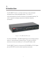
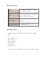
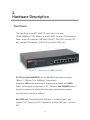
8-Port 10/100/1000 + 1 MiniGBIC Gigabit
Ethernet Smart Workgroup Switch
MIL-S8001TG
User Guide
Regulatory Approval
- FCC Class A
- UL 1950
- CSA C22.2 No. 950
- EN60950
- CE
- EN55022 Class A
- EN55024
Canadian EMI Notice
This Class A digital apparatus meets all the requirements of the Canadian Interference-Causing Equipment
Regulations.
Cet appareil numerique de la classe A respecte toutes les exigences du Reglement sur le materiel brouilleur du
Canada.
European Notice
Products with the CE Marking comply with both the EMC Directive (89/336/EEC) and the Low Voltage Directive
(73/23/EEC) issued by the Commission of the European Community Compliance with these directives imply conformity
to the following European Norms:
EN55022 (CISPR 22) - Radio Frequency Interference
EN61000-X - Electromagnetic Immunity
EN60950 (IEC950) - Product Safety
Five-Year Limited Warranty
MiLAN Technology warrants to the original consumer or purchaser that each of it's products,
and
all components thereof, will be free from defects in material and/or workmanship for a
period of five years from the original factory shipment date. Any warranty hereunder is
extended to the original consumer or purchaser and is not assignable.
MiLAN Technology makes no express or implied warranties including, but not limited to, any
implied warranty of merchantability or fitness for a particular purpose, except as expressly set
forth in this warranty. In no event shall MiLAN Technology be liable for incidental or
consequential damages, costs, or expenses arising out of or in connection with the
performance of the product delivered hereunder. MiLAN Technology will in no case cover
damages arising out of the product being used in a negligent fashion or manner.
Trademarks
The MiLAN logo and MiLAN Technology trademarks are registered trademarks of MiLAN Technology in the
United States and/or other countries.
To Contact MiLAN Technology
For prompt response when calling for service information, have the following information ready:
- Product serial number and revision
- Date of purchase
- Vendor or place of purchase
You can reach MiLAN Technology technical support at:
E-mail: [email protected]
Telephone: +1.408.744.2751
Fax: +1.408.744.2771
MiLAN Technology
1329 Moffett Park Drive
Sunnyvale, CA 94089
United States of America
Telephone: +1.408.744.2775
Fax: +1.408.744.2793
http://www.milan.com
[email protected]
© Copyright 2005
MiLAN Technology
P/N: 90000xxx Rev. x
Table of Contents
1.
Introduction
Features
Software Features
Package Contents
Ethernet Switching Technology
Management Methods
2.
Hardware Description
Front Panel
LED Indicators
Rear Panel
Desktop Installation
Attaching Rubber Feet
Power On
3.
Network Application
Small Workgroup
Segment Bridge
4. Console Management
Connecting a Terminal or PC to the Console Port
4-1. Main Menu
4-2. VLAN Mode
4-2-1. 802.1Q VLAN Configuration
4-2-1-1. Enabling 802.1Q VLAN
4-2-1-2. VLAN Configuration
4-2-1-3. Create VLAN Group
4-2-1-4. VLAN Status
4-2-2. Port-Based VLAN Configuration
4-2-2-1. Port-Based VLAN Group Configuration
4-3. QoS Control
4-4. Broadcast Storm Suppression
4-5. Restore to Default
4-6. Reset System
5. Troubleshooting
6. Technical Specifications
1.
Introduction
The MIL-S8001TG switch is a multi-port switch that can be used to build
high-performance switched workgroup networks. This switch is a
store-and-forward device that offers low latency for high-speed networking. The
switch is targeted at workgroup, department or backbone computing
environments.
Figure 1-1. The MIL-S8001TG switch
The 8-Port 10/100/1000 + 1 MiniGBIC Gigabit Ethernet Smart Workgroup Switch
features a “store-and-forward“ switching scheme. This allows the switch to
auto-learn and store source addresses in a 4K-entry MAC address table.
The MIL-S8001TG switch has 8 auto-sensing 10/100/1000 Base-TX RJ-45 ports
plus one MINI GBIC slot which enables long-distance connection.
1
Features
Conforms to IEEE 802.3 10BASE-T,IEEE 802.3u 100BASE-TX,IEEE
802.3ab 1000BASE-T,IEEE 802.3z gigabit fiber and IEEE 802.3x
8 x 10/100/1000 Base-TX RJ-45 ports
1 MINI GBIC socket for MINI GBIC Fiber transceiver
Auto-MDIX on all ports and N-Way Auto-Negotiation
16 Gbps back-plane
Quality of service (QoS) supported
IEEE802.3x Flow control
Back pressure half duplex (10/100Mbps)
Flow control full duplex (10/100/1000Mbps)
Store-and-Forward switching architecture
1.5Mbits memory buffer
Supports 9.5KB JUMBO packet
Supports Port-based VLAN and 4K 802.1Q Tag VLAN
Supports Broadcast Storm Filtering
4K MAC address table
Optional 19” rack mount kit
10” size for desktop and internal power
2
Software Features
VLAN
QOS
Port Based VLAN, support up to 8 groups
4K IEEE802.1Q Tag VLAN
2 Types of quality of service: 1.Port based
priority. 2. 802.1p/TOS priority tag
System provide 4 queues for High and Low
Priority Queue
priority.
Queue Ratio: High:Middle:Low:Lowest =8:4:2:1
Broadcast Storm filter
Disable or Enable
Package Contents
Unpack the contents of the package and verify them against the checklist
below.
MIL-S8001TG Switch
Power Cord
Four Rubber Feet
RS-232 cable
User Guide
Warranty Card
If any item is missing or damaged, please contact your local dealer for service.
3
Ethernet Switching Technology
Ethernet Switching Technology dramatically boosted the total bandwidth of a
network, eliminated congestion problems inherent with CSMA/CD (Carrier
Sense multiple access with Collision Detection) protocol, and greatly reduced
unnecessary transmissions.
This revolutionized networking. First, by allowing two-way, simultaneous
transmissions over the same port (Full-duplex), which essentially doubled the
bandwidth. Second, by reducing the collision domain to a single switch-port,
which eliminated the need for carrier sensing. Third, by using the
store-and-forward technology’s approach of inspecting each packet to intercept
corrupt or redundant data, switching eliminated unnecessary transmission that
slow the network. By employing address learning, which replaced the inefficient
receiving port.
Auto-negotiation regulates the speed and duplex of each port, based on the
capability of both devices. Flow-control allows transmission from a 100Mbps
node to a 10Mbps node without loss of data. Auto-negotiation and flow-control
may require disablement for some networking operations involves legacy
equipment. Disabling the auto-negotiation is accomplished by fixing the speed
or duplex of a port.
Ethernet Switching Technology supplied higher performance at costs lower
than other solutions. Wider bandwidth, no congestion, and the reduction in
traffic is why switching is replacing expensive routers and inefficient hubs as
the ultimate networking solution. Switching brought a whole new way of
thinking to networking.
4
Management Methods
The MIL-S8001TG switch series supports Console Management methods
Console Management is done through the RS-232 Console Port. Managing the
switch in this method requires a direct connection between a PC and the
switch.
5
2.
Hardware Description
Front Panel
The Front Panel of the MIL-S8001TG switch consists of eight
10/100/1000Base-TX RJ-45 ports, one MINI GBIC slot, one LED-Indicator for
Power, three LED-Indicators (100/1000, LNK/ACT, FDX/COL) for each UTP
port, and two LED-Indicators (LNK/ACT) for the Mini-GBIC slot.
Figure 2-1. Front panel for MIL-S8001TG
RJ-45 Ports (Auto MDI/MDIX): 8x 10/100/1000 N-way auto-sensing for
10Base-T, 100Base-TX or 1000Base-T connections.
[In general, MDI means connecting to another Hub or Switch while MDIX
means connecting to a workstation or PC. Therefore, Auto MDI/MDIX means
that you can connect to another Switch or workstation without changing
non-crossover or crossover cabling. ]
Mini GBIC slot: The optional MINI GBIC port is shared with port 1 and
supports 3.3V. There are 2 LED indicators for the Mini GBIC port – LNK and
ACT.
6
7
LED Indicators
The LED Indicators give real-time information of systematic operation status.
The following table provides descriptions of LED statuses and their meaning.
Figure 2-2. LED Indicators
LED
Power
Status
Color
Description
On
Green
Power On
On
Green
On
Orange
100/1000
The port is operating at the speed of
1000Mbps.
The port is operating at the speed of
100Mbps.
The port is operating at the speed of
10Mbps mode or no device is
Off
attached.
LNK /ACT
On
Green
Blinks
Green
Off
The port is successfully connecting
with the device.
The port is receiving or transmitting
data.
No device attached.
8
FDX /COL
On
Orange
Blinks
Orange
The port is operating in Full-duplex
mode.
Collision of Packets is occurring in
the port.
The port is operating in Half-duplex
Off
LNK (MINI
GBIC)
ACT (MINI
GBIC)
On
Blinks
mode or no device attached.
The port is successfully connecting
Green
with the device.
The port is receiving or transmitting
Green
data.
Table 2-1. Description of LED Indicators
9
Rear Panel
The 3-pronged power plug and console port are located at the rear panel of the
MIL-S8001TG as shown in Figure 2-3. The switch will work with AC in the
range 100-240V AC, 50-60Hz.
Figure 2-3. The Rear Panel of MIL-S8001TG switch
Desktop Installation
Set the switch on a sufficiently large flat space with a power outlet nearby. The
surface where you put your switch should be clean, smooth, level and sturdy.
Provide enough clearance around the switch to allow attachment of cables,
power cord and air circulation.
Attaching Rubber Feet
A. Make sure the mounting surface on the bottom of the switch is grease and
dust free.
B. Remove adhesive backing from the rubber feet.
C. Apply the rubber feet to each corner on the bottom of the Switch.
These footpads can prevent the switch from shock/vibration.
10
Power On
Connect the power cord to the power socket on the rear panel of the switch.
Connect the other end of the cord to an appropriate power outlet. The internal
power supply in the switch works with AC in the voltage range of 100-240VAC
and frequency 50~60Hz.
Check the power indicator on the front panel to see if power is properly
supplied.
11
3.
Network Application
This section provides you a few samples of network topology in witch the Switch
is used. In general, the 8 Gigabit Copper with one MINI GBIC Smart switch is
designed as a segment switch. That is, with its address table (4000 MAC address)
and high performance, it is ideal for interconnecting networking segments.
PC, workstations, and servers can communicate each other by directly
connecting with 8 Gigabit Copper with one MINI GBIC Smart switch. The switch
automatically learns nodes address, which are subsequently used to filter and
forward all traffic based on the destination address.
By using Uplink port, the Switch can connect with another switch or hub to
interconnect other small-switched workgroups to form a larger switched network.
Meanwhile, you can also use fiber ports to connect switches. The distance
between two switches via fiber cable can be up to 220 or 550 meters (multi-mode
fiber) or 60 kilometers (single-mode fiber).
Small Workgroup
The MIL-S8001TG switch can be used as a standalone switch to which
personal computers, servers, and printer servers are directly connected to form
a small workgroup.
12
Segment Bridge
For enterprise networks where large data broadcasts are constantly processed,
this switch is an ideal solution for department users to connect to the corporate
backbone.
In the illustration below, two Ethernet switches with PCs, print server, and local
server attached, are both connect to the switch. All the devices in this network
can communicate with each other through the Switch. Connecting servers to
the Switch allow other users to access the data on server.
In the below illustration, two 8 Gigabit Copper with one MINI GBIC Smart
switch are used to interconnect two small workgroups. By using fiber ports to
connect switches, the distance between two switches via fiber cable can be up
to 2Km or 30Km (SC single-mode fiber connector).
13
4.
Console Management
Connecting a Terminal or PC to the Console Port
Console management involves the administration of the switch via a direct
connection to the RS-232 console port. This port is a female DB-9 connector.
From the main menu of the console program, the user has access to manage
the functions of the switch.
Use the supplied RS-232 cable to connect a terminal or PC to the console port.
The terminal or PC to be connected must support the terminal emulation
program.
14
After the connection between the Switch and PC is finished, turn on the PC and
run a terminal emulation program or Hyper Terminal and configure its
communication parameters to match the following default characteristics of
the console port:
Baud Rate: 9600 bps
Data Bits: 8
Parity: none
Stop Bit: 1
Flow Control: None
Figure 4-1. The settings of communication parameters
After you have entered the parameter settings, press the Enter Key and the
Main Menu of console management appears.
15
4-1. Main Menu
There are five items for selection as follows.
VLAN Mode: Configure the VLAN function.
QOS Control: Configure the QoS function.
Broadcast Storm Suppression: Enable or disable Broadcast Storm filtering
function.
Restore to Default: Set the system to the default value settings.
Reset System: Restart the system.
16
4-2. VLAN Mode
Select VLAN Mode to access the VLAN configuration menu. The system
supports two VLAN modes – 802.1Q and Port-Based VLAN.
At the Main Menu command prompt, type “v” or “V” to enter the VLAN Mode
configuration interface.
Previous Menu: Enter “q” or “Q” and the command prompt to exit the current
interface.
17
4-2-1. 802.1Q VLAN Configuration
After selecting VLAN mode from the Main Menu, enter the 802.1Q VLAN
configuration interface by entering "8" at the command prompt.
Previous Menu: Enter “q” or “Q” and the command prompt to exit the current
interface.
18
4-2-1-1. Enabling 802.1Q VLAN
Prior to configuring 802.1Q VLAN, the 802.1Q VLAN function must be enabled.
Enter “e” or “E” at the 802.1Q VLAN menu command prompt to enable the
802.1Q VLAN function. To disable the 802.1Q VLAN function, enter “d” or “D”
at the command prompt.
Previous Menu: Enter “q” or “Q” and the command prompt to exit the current
interface.
19
4-2-1-2. VLAN Configuration
The Port VID can be configured for each port. Enter “v” or “V” at the 802.1Q
VLAN command prompt to the access the VLAN configuration interface. Enter
the port number to be configured. Next, enter the PVID number to be assigned
to the selected port. The PVID range is from 1 to 512.
Previous Menu: Enter “q” or “Q” and the command prompt to exit the current
interface.
20
4-2-1-3. Create VLAN Group
Enter “c” or “C” at the command prompt to access the Create VLAN Group
configuration interface.
VLAN group ID: Enter the VLAN Group ID at the prompt.
Add VLAN group member: Enter “m” or “M” at the command prompt to add
the port to the VLAN group, use the command “+port number” to add the port
or enter “+A” to add all ports. To remove the port from VLAN group, use the
command “-port number” or enter “-A” to remove all ports from group. A
maximum of 8 ports can be added to a VLAN group. After the port(s) are
added the VLAN group, enter command “q” or “Q” to exit the configuration
interface.
21
Tag/Untagged Setting: Enter “t” or “T” at the VLAN Configure command
prompt to enter Tag/Untagged Setting configuration interface. Use the
command “+port number” to set the port as the Tagged status. Use the
command “-port number” to set the port to the Untagged status. After
configuration, enter command “q” or “Q” to exit the interface.
Previous Menu: Enter “q” or “Q” and the command prompt to exit the current
interface.
22
4-2-1-4. VLAN Status
VLAN Group Information can be viewed by entering “s” or “S” at the 802.1Q
VLAN menu command prompt to access the VLAN Status interface. Enter the
VLAN group ID to display the VLAN status.
Previous Menu: Enter “q” or “Q” and the command prompt to exit the current
interface.
23
4-2-2. Port-Based VLAN Configuration
At the VLAN mode menu interface, enter “p” or “P” at the command prompt to
access the Port-Based VLAN mode configuration interface.
Previous Menu: Enter “q” or “Q” and the command prompt to exit the current
interface.
24
4-2-2-1. Port-Based VLAN Group Configuration
A maximum of 8 VLAN groups can be configured. The default VLAN group is
VLAN 1.
1. Enter the group number to configure a VLAN group. For example: enter “1”
for VLAN group 1.
2. To add a port to a VLAN group, use the command “+port number” to add
the port or enter “+A” to add all ports. To remove a port from a VLAN group,
use the command “-port number” or enter “-A” to remove all ports from the
group. In VLAN group 1, the default members are port 1 to port 8. A
maximum of 8 ports can be added to a VLAN Group.
3.
Enter “s” or “S” at the command promt to save the configuration.
4. To view the VLAN group table, enter “l” or “L”.
Previous Menu: Enter “q” or “Q” and the command prompt to exit the current
interface.
25
4-3. QoS Control
Select QoS Control to access the QoS configuration menu. The system
supports two methods of QoS control – Port-Based and 802.1P/TOS.
From the Main Menu, enter "q" or "Q" to select QoS Control to enable or
disable the Qos function and set the high/low queue priority ratio.
Port-Based Enable: Enter “p” or “P” at the command prompt to enable
Port-Based function.
802.1P/TOS Enable: Enter “e” or “E” at the command prompt to enable
802.1P/TOS function.
Note: Port-Based or 802.1P/TOS function must be anabled prior to
configuring the Priority ID Map function.
QoS Disable: To disable QoS control, enter “d” or “D” at the command
prompt.
26
Priority ID Map: To configure the QoS control high/low weight setting, enter
“m” or “M” at the command prompt. Next, enter the selection number, for port
priority setting. There are four-priority levels – High, Middle, Low, and Lowest
priority level.
High Priority: Enter "h" or "H" to enable the highest port priority setting.
Middle Priority: Enter "m" or "M" to enable the highest port priority setting.
Low Priority: Enter "l" or "L" t to enable the highest port priority setting.
Lowest Priority: Enter "s" or "S" to enable the highest port priority setting.
27
Priority ID Map Status: To display the current priority level setting for each
port, enter “s” or “S” at the command propmt. If the priority level is not
configured, the priority IP mapping will be undefined.
Restore to Default: Enter “r” or “R” at the command prompt to return the QoS
control values back to their defaults.
Previous Menu: Enter “q” or “Q” and the command prompt to exit the current
interface.
28
4-4. Broadcast Storm Suppression
Enable or disable the Broadcast storm function. In the main menu command
prompt, enter command ”b” or “B” to enter the Broadcast Storm Suppression
configuration interface. In the command prompt sign, enter command “e” or “E”
to enable the broadcast storm function. To disable the broadcast storm function,
enter command “d” or “D”.
Previous Menu: Enter “q” or “Q” and the command prompt to exit the current
interface.
29
4-5. Restore to Default
Enter “d” or “D” at the main menu command prompt to return the system to the
default values.
4-6. Reset System
Enter “r” or “R” at the main menu command prompt to restart the system.
Note: The current configuration will remain after the system has been restarted.
30
5.
Troubleshooting
This section is intended to help you solve some common problems encountered
while using the MIL-S8001TG switch.
Incorrect connections
The switch port can auto detect straight or crossover cable when you link
switch with other Ethernet device. For the RJ-45 connector should use correct
UTP or STP cable, 10/100Mbps port use 2 pairs twisted cable and Gigabit
1000T port use 4 pairs twisted cable. If the RJ-45 connector is not correct pin
on right position then the link will fail.
For fiber connection, please note that
fiber cable mode and fiber module should be match.
Faulty or loose cables
Look for loose or obviously faulty connections. If they appear to be OK, make
sure the connections are snug. If that does not correct the problem, try different
cables.
Non-standard cables
Non-standard and miss-wired cables may cause numerous network collisions
and other network problem. This can seriously impair network performance. A
category-5 cable tester is a recommended tool for every network installation.
31
Improper Network Topologies
It is important to make sure that you have a valid network topology. Common
topology faults include excessive cable length and too many repeaters or hubs
between end nodes. In addition, you should make sure that your network
topology contains no data path loops. Between any two ends nodes, there
should be only one active cabling path at any time. Data path loops will cause
broadcast storms that will severely impact your network performance.
Diagnosing LED Indicators
The switch can be easily monitored through panel indicators to assist in
identifying problems.
If the power indicator does turn on when the power cord is plugged in, you may
have a problem with the power outlet or power cord. However, if the switch
powers off after running for a while check for loose power connections, power
losses or surges at power outlet. If you still cannot resolve the problem, contact
your local dealer for assistance.
Cabling
RJ-45 ports: Use unshielded twisted-pair (UTP) or shield twisted-pair (STP)
cable for RJ-45 connections: 100
connections or 100
Category 3, 4 or 5 cable for 10Mbps
Category 5 cable for 100Mbps connections. Be sure that
the length of any twisted-pair connection does not exceed 100 meters (328
feet). Gigabit ports should use Cat-5 or Cat-5e cable for 1000Mbps
connections and the length should not exceed 100 meters.
32
6.
Technical Specifications
This section provides the specifications of the MIL-S8001TG switch product.
IEEE 802.3 10BASE-T Ethernet,
IEEE 802.3u 100BASE-TX Fast Ethernet
IEEE 802.3ab 1000BASE-T Gigabit Copper
Standard
IEEE 802.3z Gigabit fiber
IEEE802.3x Flow Control and Back-pressure
IEEE802.1p Quality of Service
IEEE802.1Q Tag VLAN
Protocol
CSMA/CD
Technology
Store-and-Forward switching architecture
14,880 pps for 10Mbps
Transfer Rate
148,800 pps for 100Mbps
1,488,000 pps for 1000Mbps
Per unit: Power
LED Indicators
Per port: 100/1000 (Orange /Green), Link/Activity
(Green), Full duplex/ Collision (Orange)
MINI-GBIC: Link, Activity (Green)
Connector
8 Gigabit Copper: RJ-45, Auto-MDI/MDI-X for all
port
33
MINI GBIC: 3.3V MINI GBIC slot shared with port #1
Back-plane
16Gbps
MAC address
4K Mac with Auto Learning
Memory
1.5Mbits for packet buffer
Dimensions
250mm x 132mm x 37mm (L x W x H)
Power Supply
Power
Consumption
Operating
Temperature
Operating Humidity
Storage
Temperature
EMI & Safety
Input: AC 100-240V, 50/60Hz
Output: 5V/4A (internal)
22 Watt (maximum)
0ºC to 45ºC (32ºF to 113ºF)
10% to 90% (Non-condensing)
-10ºC to 70ºC
FCC Class A, CE, CE/ EN60950, UL, cUL
34
Rev A
35