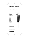
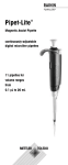
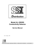
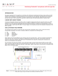
1
Operating Instructions
Pipet-Lite™ XLS™
Manual Pipettes with RFID
Single-channel
Multichannel
Adjustable Spacer
Pipet-Lite XLS
Pipet-Lite™ XLS
Manual Pipettes with RFID
•SIngle channel models with LTS or with traditional universal -fit shafts
•Multichannel models with LTS
•Adjustable spacer multichannel models with LTS
•RFID anabled. all models
Table of Contents
1.1 Introduction.........................................................................................................3
1.2 Setting Volume.....................................................................................................4
1.3 Tip Selection and Mounting....................................................................................6
1.4 Tip Immersion Depth.............................................................................................6
1.5 Operation............................................................................................................7
1.6 Autoclaving.........................................................................................................7
1.7 Tip Ejector Arm Removal.......................................................................................8
1.8 Pipet-Lite XLS Storage...........................................................................................8
1.9 Troubleshooting...................................................................................................8
1.10 Service, Calibration, and Repair.............................................................................9
1.11 Specifications......................................................................................................9
1.12 Replacement Parts.............................................................................................11
2.1 RFID Operation...................................................................................................12
3.1 Pipet-Lite XLS Multichannel..................................................................................14
4.1 Pipet-Lite XLS Adjustable-Spacer..........................................................................16
Contents of Pipet-Lite XLS box
• Pipet-Lite XLS model as ordered
• CD-ROM containing this manual and trial RFID software
• Sample Tips
• Conformance Certificate / Warranty Card
If any item is missing please call 800-472-4646 in the US, or contact your local MT office or
distributor.
Rainin, Pipet-Lite, XLS, LTS, LiteTouch, Hang-Ups are trademarks of Rainin Instrument, LLC. Pipet-Lite pipettes
are manufactured under U.S. Patent Nos. 5,614,153; 5,700,959; and 5,849,248. For use under U.S. patents
6,168,761 B1; 6,171,553 B1; and D426,643.
©2010 Rainin Instrument, LLC. No part of this manual may be copied without the express written permission of
Rainin Instrument, LLC.
2
1.1 Introduction Rainin’s new Pipet-Lite XLS is based upon Pipet-Lite
and incorporates several new features to further improve
ergonomics while maintaining high accuracy and performance. Pipet-Lite XLS is available in several versions
outlined below. This manual will describe all models.
Single-channel
11 models for volumes from 0.1 µl to 20 ml
Multichannel
12 models for volumes from 1 µl to 1200 µl,
including 8 and 12 channels
Adjustable-spacer
5 models for volumes from 5 µl to 1200 µl
including 6 and 8 channels, with nozzle spacing
adjustable from 9-19 or 9-14 mm
Spring forces in the Pipet-Lite XLS are reduced even further
over the already low forces used in Pipet-Lite: with the
low-drag seals, new contoured handle with fingerhook,
the pipette is designed for maximum comfort and enhanced performance, not compromised by fatigue over long
pipetting days.
A magnet is used to help locate and hold Pipet-Lite XLS
piston in the zero or home position, which defines the
starting point for the pipette cycle and allows the use of
lighter aspiration and blowout springs, reducing forces on
the operator’s thumb.
In models with LTS™ shafts (L-model single channels,
all multichannels and adjustable spacers), the patented
LTS LiteTouch™ Tip Ejection System reduces tip ejection
forces by up to 85% in the single-channel L models, and
provides absolutely consistent sample pickup across all
channels in multichannel models, as well as reducing tip
ejection force.
VOLUME LOCK
PLUNGER BUTTON
VOLUME SET
TIP EJECTOR
BUTTON
RFID IN
FINGER-HOOK
VOLUME
DISPLAY
RUGGED
HIGH-IMPACT
LOW THERMAL
CONDUCTIVITY
POLYMER
SHAFT
TIP EJECTOR
QUICK
RELEASE
STAINLESS STEEL
TIP EJECTOR ARM
DISPOSABLE
TIP
Figure 1: Pipet-Lite XLS
Finally, all Pipet-Lite XLS models contain an RFID
(radio-frequency identification) for facilitating calibration
management when using the optional RFID reader and
Lab-X™ Direct Pipette-Scan™ software. Using the RFID is
described after the single-channel section.
3
Single-Channel
1.2 Setting Volume
1. Turn the volume lock lever to the “unlock” position so the volume setting mechanism is unlocked and free to turn. See left image in Figure 2.
UNLOCK
LOCK
Figure 2: Volume Lock Control
2. With the mechanism unlocked, orient Pipet-Lite XLS so you are looking at the volume indicator, then rotate the plunger button to change volume – counter-clockwise to increase, and
clockwise to decrease volume.
Figure 3: Volume Indicator by Pipette Model
Read the volume indicator from the top down:
2–20 µL: Black digits indicates µl. Red digits – tenths, hundredths of µl.
100–300 µl: All digits black – µl.
1000–5000 µl: red digit – ml. Black digits– tenths, hundedths of ml.
10 ml and 20 ml: Red digit – ml. Black digits – tenths of ml.
3. To eliminate errors due to mechanical backlash: when setting the desired volume, first turn the
knob 1⁄3 turn above the desired volume. Then turn the knob slowly clockwise until the desired
volume is displayed. Always dial down to the desired volume.
4. Turn the volume lock to the “lock” position (Fig. 2 above) to prevent changes to the volume
setting. Some volumes for the 200 µL model are shown in Figure 4.
Figure 4: Example volumes
4
Volume ranges and increments for each Pipet-Lite XLS model are shown below:
Single-Channel Pipet-Lite XLS
Volume
Adjustable Range µL Recommended Range µL Increment µL
2 µL
0 to 2
0.1 to 2
0.002
10 µL
0 to 10
0.5 to 10
0.02
20 µL
0 to 20
2 to 20
0.02
100 µL
0 to 100
10 to 100
0.2
200 µL
0 to 200
20 to 200
0.2
300 µL
0 to 300
20 to 300
0.5
1000 µL
0 to 1000
100 to 1000
2.0
2000 µL
0 to 2000
200 to 2000
2.0
5000 µL
0 to 5000
500 to 5000
5.0
10 mL
0 to 10 mL
1 mL to 10 mL
20.0
20 mL
0 to 20 mL
2 mL to 20 mL
20.0
Multichannel and Adjustable-Spacers
Volume
Adjustable Range µL Recommended Range µL Increment µL
10 µL
0 to 10
0.5 to 10
0.02
20 µL
0 to 20
2 to 20
0.02
50 µL
0 to 50
5 to 50
0.05
100 µL
0 to 100
10 to 100
0.2
200 µL
0 to 200
20 to 200
0.2
300 µL
0 to 300
20 to 300
0.5
1200 µL
0 to 1200
100 to 1200
2.0
Filter
Single-Channel Pipet-Lite XLS 5000 µL, 10 mL, and 20 mL pipettes use a filter in the end
of the shaft to help prevent liquid entering the shaft and contaminating the piston, should
the plunger snap up during aspiration. Using a filter is recommended when pipetting large
volumes. Replace the filter if it gets wet.
Figure 5: Filter orientation
The 5000 µL and 10 mL pipettes use the same filter, as shown in the diagram above:
5000 µL: small diameter into the shaft.
10 mL: large diameter into the shaft.
Filter part numbers are 6190-164 (pack of 100) and 6190-165 (pack of 1000).
The filter for the 20 mL model is a cylinder.
Part numbers: 6190-221 (pack of 100), 6190-222 (pack of 500).
5
1.3 Tip Selection and Mounting Single-Channel
Rainin pipettes and tips are designed together as a pipetting system, both in LTS and traditional versions. All Rainin tips are BioClean and totally inert, so you can be assured of the best
pipetting results.
Pipet-Lite XLS pipettes are calibrated with Rainin tips, and performance to published specifications can only be guaranteed when Rainin tips are used.
To mount a tip, press the Pipet-Lite XLS shaft into the end of the tip with light force. With both
LTS and traditional versions, the tip will seal properly on the shaft with minimal force — do
not use more force than is required.
1.4 Tip Immersion Depth
The recommended depth for tip insertion into the sample for each model is shown below.
Nominal Volume
2 µL
10 µL
20 µL
100 µL
200 µL
300 µL
1000 µL
2000 µL
5000 µL
10 mL
20 mL
Volume Range
0.1 - 2 µL
0.5 - 10 µL
2 - 20 µL
10 - 100 µL
20 - 200 µL
20 - 300 µL
100 - 1000 µL
200 - 2000 µL
500 - 5000 µL
1 mL - 10 mL
2 mL - 20 mL
Immersion Depth
1-2 mm
1-2 mm
2 - 3 mm
2 - 3 mm
3 - 6 mm
3 - 6 mm
3 - 6 mm
3 - 6 mm
6 - 10 mm
6 - 10 mm
6 - 10 mm
Tip immersion depth is critical and should not be exceeded, or the volume measured may be
inaccurate, possibly out of specification. The tip angle is also important – the pipette should
always be used in a position within 20 degrees of vertical. See Figure 6 below.
TIP
ANGLE
Figure 6: Tip Immersion Depth and Tip Angle
6
1.5 Operation Before pipetting valuable samples, it is good to practice aspirating and dispensing water.
Set the desired volume as described on page 4.
Attach a new Rainin tip. Press the shaft into the tip with only sufficient force to make a good
seal.
3. Press the plunger button to the first stop, and hold it in this position.
1.
2.
1.
2.
3.
1.
2.
3.
1.
2.
3.
4.
5.
6.
7.
Aspiration:
Holding Pipet-Lite XLS vertically (or within 20° of vertical), place the tip into the sample to the
proper depth and relax your thumb pressure on the plunger. The light piston spring will move
the piston upward, aspirating sample. Do not let go of the plunger button, or the piston may
snap up quickly, resulting in inaccurate measurement.
Pause for about 1 second (longer for macro-volume pipettes) to ensure that the full volume of
sample is drawn into the tip.
Withdraw the tip from the sample. If any liquid remains on the outside of the tip, touch it off
carefully onto a lint-free tissue, taking care not to touch the tip orifice.
Dispensing:
Touch the tip end against the side wall of the receiving vessel and press the plunger slowly,
past the first stop, to blowout (bottom of stroke.)
Wait: 1 second for 2–300 µL volumes, 1-2 seconds for 1000 µL and larger.
(For viscous solutions pause before blowout.)
Still holding the plunger, withdraw the tip, sliding it along the wall of the vessel. Release the
plunger.
Press the tip ejector button lightly to discard the tip. Use a new tip for each sample to prevent
carry-over. Repeat for the next pipetting cycle.
Pipetting Guidelines
Pipet-Lite XLS pipettes incorporate several features to enhance pipetting consistency.
You should also maintain:
Consistent pickup and dispense rhythm.
Consistent speed and smoothness when pipetting.
Consistent pressure on the plunger button at the first stop.
Consistent immersion depth. See Figure 6.
Pipette vertically, or within 20° of vertical.
Pre-rinse the tip twice by aspirating and dispensing sample before actual pickup.
Don’t invert or lay the pipette flat with liquid in the tip.
More information on Good Pipetting Technique, including a Lab Poster, can be found on the
Rainin and MT websites: www.rainin.com or www.mt.com/rainin.
1.6 Autoclaving Autoclavable parts of Pipet-Lite XLS are the shaft and the tip ejector: 121°C, 1 bar, 15-20
minutes.
DO NOT autoclave the complete pipette or any parts other than the shaft and the tip ejector.
7
Single Channel
1.7 Tip Ejector Arm Removal Three types of tip ejector are used and all types can be removed with minimum effort - do not
use force.
For models up to 2000 µL, press in the quick-release tabs on the ejector arm and pull the
ejector down.
For 5000 µL and 10 mL models, grasp the top of the ejector arm and pull outward then
downward.
For the 20 mL model, pull off the lower part of the ejector arm; the upper part stays in place.
(Replace by aligning the rod with the hole in the upper part and pressing firmly.)
To replace the ejector arm (except 20 mL), insert the shaft through the large opening, align the
top with the tip ejector push-rod, and push until the ejector arm snaps in place.
Figure 7: Removing Tip Ejector Arm
1.8 Pipet-Lite XLS Storage
After use, store the pipette in a clean safe place. Pipet-Lite XLS is a precision instrument and
should be treated with the level of care appropriate for laboratory instrumentation. Three types
of hanger are available to hold your Pipet-Lite XLS conveniently when not in use.
CR-7: Free-standing carousel holds seven pipettes.
HU-M3:Set of three individual magnetic Hang-Ups™ for mounting on ferrous surfaces.
HU-S3:Three Hang-Ups attached to a clamp which fits onto a shelf
8
1.9 Troubleshooting
Problem
Possible Cause
Suggested Remedy
Leaks,
inaccuracy
Loose shaft
Tighten coupling nut by hand.
Worn seal or o-ring –
pipette volumes < 2000 µl
Replace seal and o-ring.
Worn o-ring or (for pipette volumes 5000
µl, 10ml, 20 ml) insufficient grease seal
on these pipettes
Replace o-ring and – for 5000 µl,
10 ml and 20 ml pipettes only – apply small
amount of grease.
Cracked or split shaft.
Replace shaft. Check piston is not bent. If bent,
call Rainin service for a new piston.
800-543-4030 in the US.
Sample splash inside mechanism leading
to staining and or corrosion.
Remove tip ejector arm, remove shaft and
check piston. If piston is corroded or stained,
call Rainin service for a new piston.
800-543-4030 in the US.
Rough, jerky, or
sticky plunger
movement
When removing the shaft from the pipette body, make sure the spring, seal and o-ring do not detach from the piston, especially on the smaller
models. Be careful not to bend the piston on these small models. Recalibration of Pipet-Lite XLS is only required when the piston is replaced.
1.10 Service, Calibration and Repair
It is recommended to use only genuine Rainin replacement parts such as seals, o-rings, and
shafts. It is NOT necessary to recalibrate the pipette after changing the seal, o-ring, or shaft.
Recalibration of the pipette is only necessary when the piston is replaced, and should be done
only by qualified factory-trained personnel in a Rainin approved facility.
For pipettes under warranty, please note that the warranty will be voided if the pipette has
been damaged as a result of physical or chemical abuse, or if the pipette has been repaired
or recalibrated by any service facility which is not authorized by Rainin.
In the US, call 800-543-4030 for service.
Service is also available outside the US. See www.mt.com/rainin for more information.
Acids and Corrosives
Extensive contact with corrosive fumes may result in premature seal wear and damage to the
piston. Exposure of the internal components to corrosive aerosols and fumes may be reduced
by using Rainin tips with aerosol barrier filters.
After using concentrated acids or corrosive solutions, you can disassemble Pipet-Lite XLS
and inspect and clean the piston assembly, shaft and seal / o-ring with distilled water. Use
extreme care on the 2 µl and 10 µl models to avoid damaging the small diameter piston, or
losing small items such as seals. Dry all components thoroughly and reassemble.
9
Single Channel
10
1.11 Specifications These manufacturer’s specifications should be used as guidelines when establishing your own
performance specification. Volume Increment
Accuracy
Precision
Model
µL
µL
%
µL (±)
%
µL (≤)
2 µL
0.2
0.002
12.0
0.024
6.0
0.012
1.0
2.7
0.027
1.3
0.013
2.0
1.5
0.030
0.7
0.014
10 µL
1.0
0.02
5.0
10.0
2.5
1.5
1.0
0.025
0.075
0.1
1.2
0.6
0.4
0.012
0.03
0.04
20 µL
2
0.02
10
20
7.5
1.5
1.0
0.15
0.15
0.2
2.0
0.5
0.3
0.04
0.05
0.06
* 50 µL
5
0.05
25
50
3.5
1.2
0.8
0.18
0.3
0.4
1.5
0.4
0.2
0.075
0.1
0.1
100 µL
10
0.2
50
100
3.5
0.8
0.8
0.35
0.4
0.8
1.0
0.24
0.15
0.1
0.12
0.15
200 µL
20
0.2
100
200
2.5
0.8
0.8
0.5
0.8
1.6
1.0
0.25
0.15
0.2
0.25
0.3
300 µL
30
0.5
150
300
2.5
0.8
0.8
0.75
1.2
2.4
1.0
0.25
0.15
0.3
0.375
0.45
1000 µL
100
2
500
1000
3.0
0.8
0.8
3.0
4.0
8.0
0.6
0.2
0.15
0.6
1.0
1.5
* 1200 µL 100
2
600
1200
3.6
0.8
0.8
3.6
4.8
9.6
0.6
0.2
0.15
0.6
1.2
1.8
2000 µL
200
2
1000
2000
3.0
0.8
0.8
6.0
8.0
16.0
0.6
0.2
0.12
1.2
2.0
2.4
5000 µL
500
5
2500
5000
2.4
0.6
0.6
12.0
15.0
30.0
0.6
0.2
0.16
3.0
5.0
8.0
10 mL 1 mL
20
5 mL
10 mL
5.0
1.0
0.6
50.0
50.0
60.0
0.6
6.0
0.2 10.0
0.16 16.0
20 mL 2 mL
20
5.0 100.0
10 mL
1.0 100.0
20 mL
0.6 120.0
Specifications are subject to change without notice.
* Multichannel models only in these volume ranges
0.6 12.0
0.2 20.0
0.16 32.0
1.12 Replacement Parts
The commonly-replaced parts are shown here for each volume range for Pipet-Lite XLS,
single-channel LTS and universal-fit models.
The images next to the tables represent the 200 µl model (top) and the 10 mL model
(bottom) – other models are similar.
Models
<2000 µl
Seal
O-Ring
Shaft
Tip Ejector Arm
L-2 XLS
6200-131
6200-132
6202-063
6202-071
L-10 XLS
6200-138
6200-139
6202-064
6202-071
L-20 XLS
6200-143
6200-170
6202-065
6202-071
L-100 XLS
6200-150
6200-151
6202-066
6202-073
L-200 XLS
6200-154
6200-155
6202-067
6202-073
L-300 XLS
6200-415
6200-414
6202-425
6200-419
L-1000 XLS
6200-161
6200-162
6202-068
6202-074
L-2000 XLS
6200-166
6200-167
6202-214
6200-168
SL-2 XLS
6200-131
6200-132
6200-134
6200-133
SL-10 XLS
6200-138
6200-139
6200-140
6200-133
SL-20 XLS
6200-143
6200170
6200-145
6200-144
SL-100 XLS
6200-150
6200-151
6200-147
6200-148
SL-200 XLS
6200-154
6200-155
6200-157
6200-156
SL-300 XLS
6200-415
6200-414
6200-413
6200-419
SL-1000 XLS
6200-161
6200-162
6200-160
6200-163
SL-2000 XLS
6200-166
6200-167
6200-169
6200-168
Models
>5000 µl
Piston
O-Ring
Cylinder
O-Ring
Shaft
Tip Ejector Arm
L-5000 XLS
6200-363
6200-364
6202-222
6200-373
L-10ML XLS
6200-369
6200-370
6202-223
6200-374
L-20ML XLS
6202-299
6202-300
6202-302
6202-298
SL-5000 XLS
6200-363
6200-364
6200-362
6200-373
SL-10ML XLS
6200-369
6200-370
6200-368
6200-374
SEAL
O-RING
SHAFT
EJECTOR
ARM
PISTON
O-RING
CYLINDER
O-RING
SHAFT
EJECTOR
ARM
Figure 8: Common Replacement Parts
Top < 2000 µL Bottom > 5000 µL
11
RFID Tag
2.1 RFID (Radio Frequency Identification Device) All Pipet-Lite XLS models incorporate a passive RFID tag in the finger-hook, containing unique
information about the pipette, including model type, serial number, RFID UID and service calibration information. The RFID tag can be wirelessly linked with optional reader and software
to facilitate querying calibration tracking and service reminders. The RFID tag has negligible
weight with no effect on precision or accuracy. It operates only when read by the RFID reader
and the below-mentioned software.
Optional Rainin RFID Reader
Rainin recommends a specific Rainin RFID reader that interfaces with a PC’s USB port. Rainin
does not recommend any other RFID reader. Using the Rainin RFID reader, information can
be written to the Pipette’s RFID tag in the same consistent way as it is read from the RFID tag.
The Rainin RFID Reader can be used with any Rainin RFID enabled Pipet-Lite XLS; but needs
appropriate software for it to work. The estimated range of operation of the RFID reader is up
to 5 cm.
How to read the Rainin RFID Reader LEDs (Light-emitting diodes)
LEDs
Description
Yellow
& Green
Reader powers up in this state. Reverts to this state when application is stopped
or a plug-in is disabled.
Yellow
Reader has detected a pipette. Keep pipette close to reader until LED changes to
Green (or Red).
Green
When application first starts, Green LED indicates the device is ready.
After all data is read from a pipette held close to the reader, Green LED lights up.
Red
Reader failed to read or write. Try scanning the pipet again, if not restart
software.
Yellow
& Red
Data written to the pipette does not compare with data read back from the
pipette.
Optional LabX™ Direct Pipette-Scan™ Software
Supplied on the same CD as this manual is a trial version of the Lab-X Direct Pipette-Scan
software. A full version is also available for purchase. Supported PC Operating Systems:
Microsoft Windows XP/Vista & Windows 7. Users can select any of the following languages:
Chinese (Simplified), Czech, Danish, English, French, German, Hungarian, Italian, Japanese,
Korean, Norwegian, Polish, Russian, Spanish, Swedish.
Operation Overview
An optional RFID Kit is available for purchase from Rainin. The
RFID Kit contains the Rainin recommended RFID reader and the
LabX Direct Pipette-Scan software. Once the Rainin RFID reader is
connected by USB to your PC, and the software is configured and
running, operation is simple.
Simply place the head of the pipette in the recommended position
as shown on the Rainin RFID reader, hold it steady for a few
seconds to scan the pipette’s RFID tag and read the pipette’s
information stored in its RFID tag into the software.
12
Figure 9
Rainin RFID Reader
Read-only fields from the Pipette’s RFID-Tag
A
B
Figures 10 and 11
Screen-shots of the software
A: before the pipette is scanned
B: after the pipette is scanned
The software shows the read-only data fields programmed into each pipette’s RFID tag before
it leaves the factory. These fields can ONLY be modified by Rainin when the pipet is manufactured or updated when sent in for service. The read-only fields include the RFID UID, Model
Number, Serial Number, Factory Date, Last Service Date and Next Service date. For QC or
workflow purposes, multiple RFID enabled pipettes can be scanned sequentially.
Writing Data to the RFID-Tag’s custom fields
In addition there are writable fields available on each pipette’s RFID tag that can be chosen
by the users to customize their pipettes so as to standardize their unique workflow(s). Each
customer is free to customize and/or standardize the software to suit their unique workflow(s).
Any such writing operation requires the Rainin RFID reader and the LabX Direct Pipette-Scan
software. Refer to the software help file for more instructions.
What RFID / LabX Direct Pipette-Scan Software can do
The LabX Direct Pipette-Scan software is flexible to help you customize your workflow.
Customers can standardize their departments on the new Pipet-Lite XLS pipettes and Rainin
RFID reader with LabX Direct Pipette-Scan software system based workflow and calibration
check system. This systems helps simplify the work of Quality Compliance Specialists.
It shortens the calibration check cycle, returning pipettes back to active lab use faster. In
addition, data can also be written to the Pipette’s RFID tag by configuring the custom fields
in the LabX Direct Pipette-Scan software and advanced workflows can be defined for your
custom settings.
What RFID does not do:
• Does not protect against misplacement, theft, or provide pipette’s location information
• Does not protect against erroneous data input
• Does not replace calibration stickers for businesses or displace QC professionals
• Does not validate your workflow. The validation of the workflow and CFR Part 11 regulatory
compliance remains the responsibility of the customer.
13
Multichannel
3.1 Pipet-Lite XLS Multichannel Pipettes
8 and 12-channel models Introduction
Pipet-Lite XLS multichannel pipettes are based on the Pipet-Lite XLS single-channel pipette
and use the patented LTS LiteTouch Tip Ejection System.
Two versions of the Multichannel Pipet-Lite XLS are
available: 8-channel and 12-channel. An 8-channel
version is shown in Figure 12.
The 8- and 12-channel models are available in 6
volume ranges:
0.5 -10 µL,
2-20 µL
5-50 µL,
20-200 µL
20-300 µL,
100-1200 µL.
Tip Selection
Pipet-Lite XLS multichannel pipettes use Rainin LTS tips.
L8-10, L8-20, L12-10, L12-20: 20µl LTS tips
VOLUME LOCK
PLUNGER
BUTTON
VOLUME SET
RFID IN
FINGER-HOOK
TIP EJECTOR
BUTTON
VOLUME
DISPLAY
LIQUID
END
MANIFOLD
L8-50, L12-50, L8-200, L12-200: 250 µl LTS tips
L8-300, L12-300: 300 µl LTS tips
L8-1200, L12-1200: 1200 µl LTS tips (recommended) or
1000 µl LTS tips – pick up 1200 µl (except with filter)
LTS tips have a cylindrical cross-section with a well-defined
seal ring, thin wall, and positive stop. They seal properly
on the shaft and cannot be jammed or forced too far onto
the shaft nozzles, and provide absolutely consistent sample
pickup across all channels.
LTS DISPOSABLE TIPS
Figure 12: Pipet-Lite XLS
Multichannel Pipette
Mounting LTS Tips: 8- and 12-channel
Mounting racked LTS tips on L8 and L12 pipettes is simple. First align the shaft nozzles into
the row of tips, holding the pipette at an angle. (Figure 13A). Position the pipette upright and
press the nozzles into the tips until the “positive stop” is reached. (Figure 13B). The tips are
now mounted with proper sealing. You do not need to hand-tighten, use heavy pressure, or
“rock” the nozzles onto the tips to obtain a good seal.
14
Figure 13: Mounting racked LTS Tips, L8 and L12
Tip Immersion Depth
The recommended depth for tip insertion is shown in the table below.
Pipet-Lite XLS Model
L8-10, L12-10 L8-20, L12-20
L8-200, L12-200, L8-300, L12-300, L8-1200, L12-1200
Immersion Depth
2 - 3 mm
3 - 6 mm
Positioning the Liquid End Manifold
The liquid end manifold can be rotated to any angle for convenience when filling plates. You
do not need to loosen the coupling nut.
15
4.1 Pipet-Lite XLS Multichannel Pipette with Adjustable
Spacing
6 and 8-channel models
Adjustable-Spacer
PLUNGER
BUTTON
VOLUME SET
VOLUME LOCK
Introduction
Pipet-Lite XLS Adjustable-Spacer multichannel
pipettes are based on Pipet-Lite XLS single-channel
models, and operate in the same way.
RFID IN
FINGER-HOOK
VOLUME
DISPLAY
Two versions of the Pipet-Lite XLS AdjustableSpacer pipette are available: 6-channel (LA6) and
8-channel (LA8), with nozzle spacing adjustment
ranges shown below:
6-channel
9 mm to approx. 19 mm
8-channel 9 mm to approx. 14 mm
6- and 8-channel versions are available in the
volume ranges: 20-300 µL and 100-1200 µL.
8-channel versions are also available in the
5-50 µL volume range.
LIQUID END
MANIFOLD
LIMITER KNOB
Spacing Controls and Indicators
Nozzle spacing is changed with the use of two
knurled knobs on either end of the liquid end manifold: the LIMITER knob and the SPACING ADJUSTMENT knob, shown in Figure 14.
The LIMITER knob (marked with the nozzle spacing
range) sets the desired maximum spacing within
the pipette’s spacing range. A vertical arrow at the
top of the knob on the liquid end manifold is the set
point, shown in Figure 15.
When you have set the maximum spacing with the
LIMITER knob, turn the SPACING adjustment knob
to open the nozzle spacing to the set value. A scale
on the liquid end manifold gives a visual reference
of the set spacing. Simply line up the the leftmost
nozzle with the scale on the manifold, as shown in
Figure 15.
SPACING
ADJUSTMENT KNOB
LTS DISPOSABLE TIPS
Figure 14: Pipet-Lite XLS
Adjustable-Spacer Pipette
SET POINT
Figure 15: Liquid End Marks
16
TIP
EJECTOR
BUTTON
The full range of adjustment for the eight-channel version is shown below in Figure 17.
Nozzles are set to 9 mm spacing on the left and 14 mm spacing on the right.
Figure 16: Nozzles: minimum spacing & maximum spacing
Tip Selection
Pipet-Lite multichannel pipettes must use Rainin LTS tips.
LA8-50: use 250 µl LTS tips
LA6-300 and LA8-300: use 300 µl LTS tips
LA6-1200 and LA8-1200: use 1200 µl LTS tips (recommended) or 1000 µl LTS tips – picks
up 1200 µl (except tips with filters)
LTS tips have a cylindrical cross-section with a well-defined seal ring, thin wall, and positive
stop. They seal properly on the LTS nozzles and cannot be jammed or forced too far onto the
nozzles.
Mounting LTS Tips
Mounting racked LTS tips onto LA6 and LA8 pipettes is simple.
Set the nozzle spacing to 9 mm (same as the spacing for racked tips) by rotating the dark
grey SPACING ADJUSTMENT knob fully clockwise.
Align the nozzles into the row of tips, holding the pipette at a slight angle. (Figure 17 left).
Rotate the pipette upright and press the nozzles into the tips until the “positive stop” is
reached.
The tips are now mounted with proper sealing. You do not need to hand-tighten, use heavy
pressure, or “rock” the nozzles onto the tips to obtain a good seal. Withdraw the tips from the
tip rack. (Figure 17 right)
Figure 17: Mounting LTS Tips
17
Adjustable Spacer
Setting the Nozzle Spacing
With tips mounted on the nozzles, and before you begin to aspirate sample:
• If you know the spacing for the receiving wells or test-tube block, set this value on the
LIMITER knob.
• If you do not know the spacing, hold the pipette so that the tip ends are above the centers
of the wells or test-tube block into which you will dispense. Look at the scale on the liquid
end manifold, and note where the marked nozzle aligns. Set this value on the LIMITER
knob.
• If you accidentally over-extend the spacing, you can click the LIMITER knob to smaller
values, stopping when the tip ends are aligned over the centers of the wells/test tubes.
Once the LIMITER knob has been set, spacing the nozzles properly is simple.
Just pick up sample, set the nozzle spacing by moving the SPACING ADJUSTMENT knob until
it stops at the value set by the LIMITER knob, and dispense into the wells or test-tube block.
Tip Immersion Depth
Recommended depth for tip insertion for each Pipet-Lite XLS adjustable-nozzle model:
LA8-50: 2–3 mm
LA6-300, LA8-300, LA6-1200, LA8-1200: 3–6 mm
Operate the pipette within 20 degrees of vertical.
Tip Ejection
Simply press on the tip ejector button. All tips are ejected cleanly with minimal pressure on the
thumb because of the progressive eject design built in to the liquid end manifold.
Positioning the Liquid End Manifold
The liquid end manifold can be rotated to any angle for convenience. You do not need to
loosen the coupling nut.
18
19
www.rainin.com
For
information
Visitmore
for more
information
Rainin Instrument, LLC.
7500 Edgewater Drive
Oakland, CA 94621
Sales +1 510 564-1600
Service +1 510 564 1600
Subject to technical changes
© 2010 Rainin Instrument LLC
Printed in USA 9920-386 Rev E
a METTLER TOLEDO Company
220