1
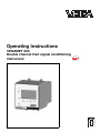
Operating Instructions
VEGAMET 625
Double channel Hart signal conditioning
instrument
WE'VE GOT
O
ABILITY
in
out
Contents
Contents
1
About this document
1.1
1.2
1.3
2
.
.
.
.
.
.
.
.
.
.
.
.
.
.
.
.
.
.
.
.
.
.
.
.
.
.
.
.
.
.
.
.
.
.
.
.
.
.
.
.
.
.
..
..
..
..
..
..
..
Configuration. . . . . . .
Principle of operation .
Adjustment . . . . . . . .
Storage and transport
.
.
.
.
.
.
.
.
.
.
.
.
.
.
.
.
.
.
.
.
.
.
.
.
.
.
.
.
.
.
.
.
.
.
.
.
.
.
.
.
.
.
.
.
.
.
.
.
.
.
.
.
.
.
.
.
.
.
.
.
.
.
.
.
.
.
.
.
.. 8
.. 9
.. 9
. . 10
General instructions. . . . . . . . . . . . . . . . . . . . . 11
Mounting information . . . . . . . . . . . . . . . . . . . . 11
Preparing the connection . . . . . . . . . . . . . . . . . 13
Connection procedure . . . . . . . . . . . . . . . . . . . 14
Wiring plans . . . . . . . . . . . . . . . . . . . . . . . . . . 16
Adjustment system . . . . . . . . . . . . . . . . . . . . . 18
Setup procedure . . . . . . . . . . . . . . . . . . . . . . . 19
Menu schematic . . . . . . . . . . . . . . . . . . . . . . . 28
Connecting the PC . . . . . . . . . . . . . . . . . . . . . 38
Parameter adjustment with PACTware™. . . . . . 41
Setup web server/e-mail, remote enquiry. . . . . . 42
Interface measurement with VEGAFLEX 67. . . . 43
Flow measurement . . . . . . . . . . . . . . . . . . . . . 44
VEGAMET 625 - Double channel Hart signal conditioning instrument
28970-EN-050616
Application examples
8.1
8.2
2
.
.
.
.
.
.
.
Setup with PACTware™
7.1
7.2
7.3
8
.
.
.
.
.
.
.
Setup with the integrated indicating and adjustment
unit
6.1
6.2
6.3
7
.
.
.
.
.
.
.
Connecting to power supply
5.1
5.2
5.3
6
6
6
6
6
6
7
7
.
.
.
.
.
.
.
Mounting
4.1
4.2
5
Authorised personnel . . . . . . . .
Appropriate use. . . . . . . . . . . .
Warning about misuse . . . . . . .
General safety instructions . . . .
CE conformity . . . . . . . . . . . . .
Safety information for Ex areas.
Environmental instructions . . . .
Product description
3.1
3.2
3.3
3.4
4
5
5
5
For your safety
2.1
2.2
2.3
2.4
2.5
2.6
2.7
3
Function . . . . . . . . . . . . . . . . . . . . . . . . . . . . .
Target group . . . . . . . . . . . . . . . . . . . . . . . . . .
Symbolism used . . . . . . . . . . . . . . . . . . . . . . .
Contents
9
Maintenance and fault rectification
9.1
9.2
9.3
Maintenance . . . . . . . . . . . . . . . . . . . . . . . . . . 47
Fault rectification . . . . . . . . . . . . . . . . . . . . . . . 47
Instrument repair . . . . . . . . . . . . . . . . . . . . . . . 50
10 Dismounting
10.1 Dismounting procedure . . . . . . . . . . . . . . . . . . 51
10.2 Disposal . . . . . . . . . . . . . . . . . . . . . . . . . . . . . 51
11 Supplement
28970-EN-050616
11.1 Technical data. . . . . . . . . . . . . . . . . . . . . . . . . 52
11.2 Dimensions . . . . . . . . . . . . . . . . . . . . . . . . . . . 56
11.3 Certificate . . . . . . . . . . . . . . . . . . . . . . . . . . . . 57
Note:
The operating instructions manual "RS232/Ethernet connection" as well as the additional instructions manual "ModbusTCP, VEGA ASCII protocol" is attached to instructions with
RS232/Ethernet interface. Here you will find further information
for setup.
VEGAMET 625 - Double channel Hart signal conditioning instrument
3
About this document
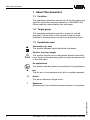
1 About this document
1.1 Function
This operating instructions manual has all the information you
need for quick setup and safe operation of VEGAMET 625.
Please read this manual before you start setup.
1.2 Target group
This operating instructions manual is directed to trained
personnel. The contents of this manual should be made
available to these personnel and put into practice by them.
1.3 Symbolism used
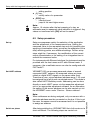
Information, tip, note
This symbol indicates helpful additional information.
Caution, warning, danger
This symbol informs you of a dangerous situation that could
occur. Ignoring this cautionary note can impair the person and/
or the instrument.
Ex applications
This symbol indicates special instructions for Ex applications.
l
List
The dot set in front indicates a list with no implied sequence.
à
Action
This arrow indicates a single action.
1
Sequence
Numbers set in front indicate successive steps in a procedure.
28970-EN-050616
4
VEGAMET 625 - Double channel Hart signal conditioning instrument
For your safety
2 For your safety
2.1 Authorised personnel
All operations described in this operating instructions manual
must be carried out only by trained specialist personnel
authorised by the operator. For safety and warranty reasons,
any internal work on the instruments must be carried out only
by personnel authorised by the manufacturer.
2.2 Appropriate use
VEGAMET 625 is a universal signal conditioning instrument
and power supply unit for connection of two HART sensors.
2.3 Warning about misuse
Inappropriate or incorrect use of the instrument can give rise to
application-specific hazards, e.g. vessel overfill or damage to
system components through incorrect mounting or adjustment.
2.4 General safety instructions
VEGAMET 625 is a high-tech instrument requiring the strict
observance of standard regulations and guidelines. The user
must take note of the safety instructions in this operating
instructions manual, the country-specific installation standards
(e.g. the VDE regulations in Germany) as well as all prevailing
safety regulations and accident prevention rules.
2.5 CE conformity
VEGAMET 625 is in CE conformity with EMC (89/336/EWG)
and NSR (73/23/EWG).
28970-EN-050616
Conformity has been judged acc. to the following standards:
l
EMC:
- Emission EN 61326: 1997 (class A)
- Susceptibility EN 61326: 1997/A1: 1998
l
NSR: EN 61010-1: 2001
VEGAMET 625 is designed for use in an industrial environment. Nevertheless, electromagnetic interference from electrical conductors and radiated emissions must be taken into
account, as is usual with a class A instrument acc. to
VEGAMET 625 - Double channel Hart signal conditioning instrument
5
For your safety
EN 61326. If VEGAMET 625 is used in a different environment,
the electromagnetic compatibility to other instruments must be
ensured by suitable measures.
2.6 Safety information for Ex areas
Please note the Ex-specific safety information for installation
and operation in Ex areas. These safety instructions are part of
the operating instructions manual and come with the Exapproved instruments.
2.7 Environmental instructions
Protection of the environment is one of our most important
duties. That is why we have introduced an environment
management system with the goal of continuously improving
company environmental protection. The environment management system is certified acc. to DIN EN ISO 14001.
Please help us fulfil this obligation by observing the environmental instructions in this manual:
l
l
Chapter "Storage and transport"
Chapter "Disposal"
28970-EN-050616
6
VEGAMET 625 - Double channel Hart signal conditioning instrument
Product description
3 Product description
3.1 Configuration
Scope of delivery
The scope of delivery encompasses:
l
l
l
l
l
Components
VEGAMET 625 signal conditioning instrument
Socket
Coded pins and bridges
RS232 modem connection cable (optional)
Documentation
- this operating instructions manual
- operating instructions manual "RS232/Ethernet connection" (optional)
- Additional instruction manual "Modbus-TCP, VEGA
ASCII protocol" (optional)
- Ex-specific safety instructions (with Ex versions) and, if
necessary, further certificates
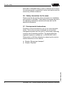
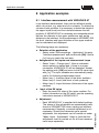
VEGAMET 625 consists of the following components:
l
l
l
l
VEGAMET 625 signal conditioning instrument with indicating and adjustment unit in the front
Communication interface for VEGACONNECT
RS232 or Ethernet interface (optional)
Socket
1
1
2
3
4
5
6
7
8
2
1
2
3
3
COM
ESC
6
28970-EN-050616
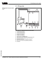
Fig.
1
2
3
4
5
6
4
Ser. No.
12345678
VEGAMET
9 10
5
OK
on
17 18
11 12
20 21 22
13 14
15 16
23 24 25 26 27 28
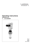
1: VEGAMET 625
Ex separating chamber with Ex version
VEGAMET 625
Indicating and adjustment unit
Communication interface for VEGACONNECT (I²C)
RS232 or Ethernet interface (optional)
Socket
VEGAMET 625 - Double channel Hart signal conditioning instrument
7
Product description
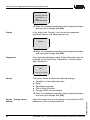
3.2 Principle of operation
Area of application
VEGAMET 625 is a universal signal conditioning instrument for
a number of applications such as level, gauge, interface and
process pressure measurement. At the same time, it can serve
as power supply unit for connected sensors. VEGAMET 625 is
designed for connection of two independent VEGA HART
sensors. Hence two independent measurements can be
carried out. By means of a third measurement loop, the
difference between the two input values can be calculated.
With instruments with an optional interface (RS232/Ethernet)
the measured values can be retrieved via modem or network
and displayed by means of a web browser or Visual VEGA. It is
also possible to send measured values and messages via email.
Physical principle
VEGAMET 625 signal conditioning instrument can power the
connected sensors and also evaluate their measuring signals.
The requested parameter is indicated in the display and, in
addition, outputted to the integrated current outputs for further
processing. Hence the measuring signal can be transmitted to
a remote display or a connected control system. In addition,
three level relays for control of pumps or other actuators are
integrated.
Power supply
Wide-range power supply unit with 20 … 253 V AC/DC for
world-wide use.
You can find detailed information on the power supply in the "
Technical data " in the " Supplement ".
3.3 Adjustment
VEGAMET 625 can be adjusted with the following adjustment
media:
l
l
the integrated indicating and adjustment unit
an adjustment software acc. to FDT/DTM standard, e.g.
PACTware™ and a Windows PC
The entered parameters are generally saved in VEGAMET
625, when used with PACTware™ also optionally in the PC.
8
VEGAMET 625 - Double channel Hart signal conditioning instrument
28970-EN-050616
Information:
When PACTware™ and the corresponding VEGA-DTMs are
used, additional settings can be made which are either not
possible or partially restricted with the integrated indicating
Product description
and adjustment unit. If an adjustment software is used, you
either need one of the integrated interfaces (RS232/Ethernet)
or the interface converter VEGACONNECT.
Further instructions for setting up the web server and e-mail
functions are stated in the online help of PACTware™ or the
VEGAMET 625 DTM as well as the operating instructions
manual "RS232/Ethernet connection".
3.4 Storage and transport
Packaging
Your instrument was protected by packaging during transport.
Its capacity to handle normal loads during transport is assured
by a test acc. to DIN EN 24180.
The packaging of standard instruments consists of environment-friendly, recyclable cardboard. For special versions PE
foam or PE foil is also used. Dispose of the packaging material
via specialised recycling companies.
Storage and transport temperature
l
28970-EN-050616
l
Storage and transport temperature see "Supplement –
Technical data – Ambient conditions"
Relative humidity 20 … 85 %
VEGAMET 625 - Double channel Hart signal conditioning instrument
9
Mounting
4 Mounting
4.1 General instructions
Installation location
Each series 600 instrument consists of the actual signal
conditioning instrument as well as a plug-in socket for carrier
rail mounting. Because it has protection class IP 30 or IP 20,
the instrument is intended to be used in switching cabinets.
4.2 Mounting information
Mounting
The plug-in socket is constructed for carrier rail mounting acc.
to EN 50022. Power supply is connected to terminals 17 and
18. For neighbouring series 600 signal conditioning instruments, it is possible to continue connection L1 and N directly
via the supplied bridges.
Danger:
The bridges must never be used with single instruments or at
the end of a row of instruments. If this rule is not heeded, there
is a danger of coming into contact with the operating voltage or
causing a short circuit.
A VEGAMET 625 in Ex version is an auxiliary, intrinsically safe
instrument and must not be installed in hazardous areas.
Before setup, the Ex separating chamber must be attached (as
shown below) with Ex versions. Safe operation can be only
ensured if the operating instructions manual and the EU type
approval certificate are observed. VEGAMET 625 must not be
opened.
Instrument coding
All signal conditioning instruments are provided with different
gaps dependent on type and version (mechanical coding).
The plug-in socket is provided with coded pins that can be
inserted to prevent accidental interchanging of the various
instrument types.
10
VEGAMET 625 - Double channel Hart signal conditioning instrument
28970-EN-050616
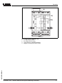
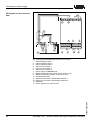
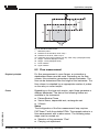
With a VEGAMET 625 in Ex version, the supplied coded pins
(type coded pin and Ex coded pin) must be inserted by the
user acc. to the below chart.
Mounting
1
1
2
3
Ao
Bo
Co
1o
2o
3o
o
o
o
4
VEGA
N
L1
5
6
7
Ao
Bo
Co
1o
2o
3o
4o
5o
6o
7o
8o
9o
10 o
11 o
12 o
8
VEGA
2
3
N
L1
4
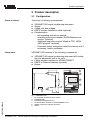
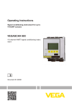
2: Plug-in socket VEGAMET 625
Ex separating chamber
Ex coding with Ex version
Type coding for VEGAMET 624/625
Bridges for looping the power supply
28970-EN-050616
Fig.
1
2
3
4
7o
8o
9o
o
o
12 o
4
VEGAMET 625 - Double channel Hart signal conditioning instrument
11
Connecting to power supply
5 Connecting to power supply
5.1 Preparing the connection
Note safety instructions
Always observe the following safety instructions:
l
l
Connect only in the complete absence of line voltage
If overvoltages are expected, overvoltage arresters should
be installed.
Tip:
We recommend VEGA overvoltage arresters B61-300 (power
supply VEGAMET 625) and B62-36G (sensor supply).
Take note of safety
instructions for Ex
applications
In hazardous areas you should take note of the appropriate
regulations, conformity and type approval certificates of the
sensors and power supply units.
Select power supply
The power supply can be 20 … 253 V AC, 50/60 Hz.
Select connection cable
Power supply of VEGAMET 625 is connected with standard
cable acc. to the national installation standards.
Standard two-wire cable with screening can be used for
connecting the sensors. The screening is absolutely necessary to ensure interference-free operation with HART sensors.
Cable screening and grounding
Connect the cable screen on both ends to ground potential. In
the sensor, the screen must be connected directly to the
internal ground terminal. The ground terminal outside on the
sensor housing must be connected to the potential equalisation.
If potential equalisation currents are expected, the screen
connection on VEGAMET 625 must be made via a ceramic
capacitor (e.g. 1 nF, 1500 V). The low frequency potential
equalisation currents are thus suppressed, but the protective
effect against high frequency interference signals remains.
Take note of the corresponding installation regulations for Ex
applications. In particular, make sure that no potential
equalisation currents flow over the cable screen. In case of
grounding on both sides this can be achieved by the use of a
capacitor or a separate potential equalisation.
12
VEGAMET 625 - Double channel Hart signal conditioning instrument
28970-EN-050616
Select connection
cable for Ex applications
Connecting to power supply
5.2 Connection procedure
Tip:
Before the actual setup, each HART sensors must be
assigned an address (see chapter "Setup"). When assigning
an address, only one sensor should be connected to
VEGAMET 625. Depending on the installation location of the
sensors, it can be advantageous to carry out this addressing
before installing and connecting the sensors. This can be
conveniently carried out e.g. in the workshop. You just need a
24 Volt power supply as well as an indicating and adjustment
module PLICSCOM or the adjustment software PACTware™
with VEGACONNECT.
Move to electrical connection and proceed as follows:
1
Snap the socket without VEGAMET 625 onto the carrier
rail
2
Connect sensor cable to terminal 1/2 (active input) or 3/4
(passive input), provide a screening
3
When using several sockets, loop the power supply by
means of bridges
4
Connect power supply (switched off) to terminal 17 and 18
5
If necessary, connect relays or other outputs
6
Insert VEGAMET 625 into the plug-in socket and screw it
down tightly
The electrical connection is finished.
28970-EN-050616
Before setting up Ex versions, make sure the Ex separating
chamber is plugged onto the left side of the housing (above the
sensor terminals). The pins for type and Ex coding must also
be inserted correctly.
Information:
l On the active input (terminals 1/2), VEGAMET 625
provides the power supply for the connected sensors.
Power supply and measured value transmission are
carried out via the same two-wire cable. This operating
mode is intended for sensors without separate power
supply (sensors in two-wire version).
l On the passive input (terminals 3/4), the sensors are not
powered, only the measured value is transmitted. This
input is for connection of transmitters with their own,
VEGAMET 625 - Double channel Hart signal conditioning instrument
13
Connecting to power supply
separate power supply (sensors in four-wire version). The
connection and operation in Ex ia is not permitted on the
passive input.
Note:
VEGAMET 625 is designed for connection of two HART
sensors. Because they are accessed via different addresses in
the HART multidrop mode, both sensors are connected to the
same sensor input. These are either terminals 1/2 (active
input) or terminals 3/4 (passive input). Simultaneous mixed
operation on active and passive input is not possible. Because
this is a digital bus system, only one two-wire cable should
lead to the two sensors. A distributor can be connected directly
in front of the sensors. As an alternative, the connection to the
next sensor can be continued via the second cable entry in the
sensor housing.
28970-EN-050616
14
VEGAMET 625 - Double channel Hart signal conditioning instrument
Connecting to power supply
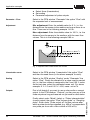
5.3 Wiring plans
Wiring plan for two-wire sensors
10
+ -
+ -
1
3
2
8
4
5
6
7
8
9
13
4
9 10
5
6
+ -
+ -
+ -
11 12
13 14
15 16
17 18 19 20 21 22
23 24 25 26 27 28
+ -
11
12
L1 N
7
2
3
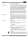
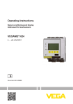
3: Wiring plan VEGAMET 625 with two-wire sensors
Internal operating relay 1
Internal operating relay 2
Internal operating relay 3
Internal current output 1
Internal current output 2
Internal current output 3
Power supply of VEGAMET 625
Measured data input with sensor supply (active input)
Measured data input (passive input), not in Ex ia
Internal fail safe relay
HART two-wire sensor with Multidrop address 1
HART two-wire sensor with Multidrop address 2
Distributor
28970-EN-050616
Fig.
1
2
3
4
5
6
7
8
9
10
11
12
13
1
VEGAMET 625 - Double channel Hart signal conditioning instrument
15
Connecting to power supply
Wiring plan for four-wire sensors
10
+ -
+ -
1
3
2
8
4
5
6
7
8
9
13
4
9 10
5
6
+ -
+ -
+ -
11 12
13 14
15 16
17 18 19 20 21 22
23 24 25 26 27 28
+ -
11
14
Fig.
1
2
3
4
5
6
7
8
9
10
11
12
13
14
12
L1 N
7
1
2
3
4: Wiring plan VEGAMET 625 with four-wire sensors
Internal operating relay 1
Internal operating relay 2
Internal operating relay 3
Internal current output 1
Internal current output 2
Internal current output 3
Power supply of VEGAMET 625
Measured data input with sensor supply (active input)
Measured data input (passive input), not in Ex ia
Internal fail safe relay
HART four-wire sensor with Multidrop address 1
HART four-wire sensor with Multidrop address 2
Distributor
Power supply for four-wire sensors
28970-EN-050616
16
VEGAMET 625 - Double channel Hart signal conditioning instrument
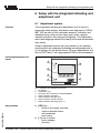
Setup with the integrated indicating and adjustment unit
6 Setup with the integrated indicating and
adjustment unit
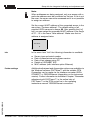
6.1 Adjustment system
Function
The integrated indicating and adjustment unit is used for
measured value display, adjustment and diagnosis of VEGAMET 625 as well as the connected sensors. Indication and
adjustment are made via four keys and a clear, graphiccapable indication with background lighting. The adjustment
menu with language selection is clearly structured and enables
easy setup.
Certain adjustment options are not possible or are partially
restricted with the integrated indicating and adjustment unit, e.
g. the settings for the e-mail server. For such applications, the
use of PACTware™ with appropriate DTMs is recommended.
Indicating/Adjustment elements
7
1
1
2
3
6
COM
5
4
2
ESC
28970-EN-050616
3
on
VEGAMET
Key functions
OK
Ser. No.
12345678
Fig.
1
2
3
4
5
6
7
5: Indicating and adjustment elements
LC display
Adjustment keys
Communication interface for VEGACONNECT
Status indication operation
Status indication fail safe relay
Status indication interface activity
Status indication operating relay 1-3
l
[OK] key:
- move to the menu overview
- confirm selected menu
- edit parameter
- save value
[–>] key to select:
- menu change
- list entry
l
VEGAMET 625 - Double channel Hart signal conditioning instrument
17
Setup with the integrated indicating and adjustment unit
l
l
- editing position
[+] key:
- modify value of a parameter
[ESC] key:
- interrupt input
- jump to the next higher menu
Note:
Approx. 10 minutes after the last pressing of a key, an
automatic reset to measured value indication is triggered. Any
values not confirmed with [OK] will not be saved.
6.2 Setup procedure
Set up
Setup encompasses mainly the selection of the application
and the adjustment of the measurement loop. Scaling the
measured value to the requested size and unit (possibly also
applying a linearization curve), as well as the adaptation of the
relay switching points, are additional settings. Further setup
steps might be, if necessary, the modification of the current
output characteristics or the setting of an integration time to
smooth the measured value.
For instruments with Ethernet interface, the instrument must be
provided with the host name and IP addr./Subnet mask. If
necessary, the e-mail/web server can also be configured with
PACTware™.
Set HART address
VEGAMET 625 can process measured values of several
connected HART sensors. All measured values are transmitted as digital HART signals on the same cable (bus).
Therefore an own, unique address (address range 1-15) must
be assigned first of all to each connected sensor. This mode is
also called HART Multidrop mode. Addressing can be done
directly on each HART sensor via the respective adjustment
unit or an appropriate adjustment software. As an alternative,
the setting of the sensor address can be also carried out via
the VEGAMET menu under "Service – Sensor address".
Switch on phase
After being switched on, VEGAMET 625 first of all carries out a
short self-check. The following steps are carried out:
18
VEGAMET 625 - Double channel Hart signal conditioning instrument
28970-EN-050616
Note:
When addresses are being assigned, only one sensor with a
particular address must be connected on the bus. If this is not
the case, the sensor cannot be accessed and it is not possible
to assign an address.
Setup with the integrated indicating and adjustment unit
l
l
l
Internal check of the electronics
indication of the instrument type, firmware version as well
as the instrument TAG (instrument name)
the output signals jump briefly to the set fault current
Then the current measured values will be displayed and
outputted.
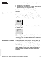
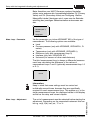
Measured value indication/
Main menu
As requested, the measured value display shows the
individual measurement loops separately or in a joint overview.
The respective digital display value, the measurement loop
designation (meas. loop TAG) and the unit are shown. With the
separate presentation, an analogue bar graph is also displayed and the measured values appear in bigger font size.
32.6
%
TAG-No.1
■
By pushing [OK] you move from the measured value indication
to the main menu.
▶
Device settings
Measurement loops
Display
Diagnostics
Service
Info
With the initial setup, you should select all submenu items of
"Device settings" and enter the correct settings.
à Select the menu item Device settings with [–>] and confirm
with [OK].
28970-EN-050616
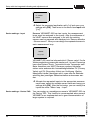
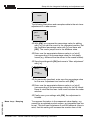
Device settings – Application
Under the menu item "Device settings", you can select the
requested application. For all level, gauge and differential
measurements, the application "Standard" is correct.
If an interface measurement should be carried out with a
VEGAFLEX 67, you have to choose the menu item "Interface
measurement" as application. After the configuration of the
inputs, the exact DK value for the upper medium must be
entered. For further information see chapter "Application
examples".
VEGAMET 625 - Double channel Hart signal conditioning instrument
19
Setup with the integrated indicating and adjustment unit
Application
▶ Standard
Interface
à Select the requested application with [–>] and save your
settings with [OK]. Then move to the menu item Input with
"[–>]".
Device settings – Input
Because VEGAMET 625 has two inputs, the measurement
loops must be assigned to the inputs. After the addresses of
the HART sensors are assigned, a list with the existing
sensors can be prepared and displayed via "Sensor selection
– Sensor search". Now you can assign the requested sensor to
each measurement loop.
Input 1
undefined
Change input?
VEGAMET 625 must be informed which "Sensor value" für die
Weiterverarbeitung verwendet werden soll. Je nach Sensortyp
kann dies Distanz, Druck, Trennschicht oder Temperatur sein.
Beim Anschluss von HART-Sensoren anderer Hersteller
stehen unter anderem die Auswahlmöglichkeiten PV (Primary
Value) und SV (Secondary Value) zur Verfügung. Welche
Messgröße hierbei übertragen wird, muss aus der Betriebsanleitung des jeweiligen Sensorherstellers entnommen werden.
à Allocate the requested inputs to the appropriate measure-
ment loops, select the suitable sensor value and save your
settings with [OK]. After the first setup, you can modify the
inputs als under "Meas. loop – Input".
You can assign an unambiguous name to VEGAMET 625 via
the Device-TAG. This function is recommended when several
VEGAMETs are implemented and a good documentation of
larger system is required.
20
VEGAMET 625 - Double channel Hart signal conditioning instrument
28970-EN-050616
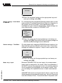
Device settings – Device-TAG
Setup with the integrated indicating and adjustment unit
Device-TAG
Device Name
à Enter the requested values via the appropriate keys and
save your settings with [OK].
Device settings – Host Name/
IP address
For instruments with integrated Ethernet interface also a host
name and the IP address must Subnet Mask for integration in
the network must be entered. These specifications are
available from your network administrator. These settings are
only effective after a restart of VEGAMET 625.
LAN/Internet
IP address:
192.168.200.200
Subnet Mask:
255.255.255.0
Change?
à Enter the values via the appropriate keys and save your
settings with [OK]. Disconnect briefly the supply voltage so
that the modified settings become effective.
Device settings – Time/Date
On instruments with integrated RS232/Ethernet interface, the
date and time can be entered in this menu item. These time
settings are buffered for approx. 3 days in case of power loss.
Time/Date
8:40
28.09.2004
à Enter the values via the appropriate keys and save your
settings with [OK].
28970-EN-050616
Meas. loop - Input
Because VEGAMET 625 has two inputs, the measurement
loops must be assigned to the inputs. After the addresses of
the HART sensors are assigned, a list of the existing sensors
can be prepared and displayed via the sensor search. Now
you can assign the requested sensor to each measurement
loop.
VEGAMET 625 must be informed which "Sensor value" für die
Weiterverarbeitung verwendet werden soll. Je nach Sensortyp
kann dies Distanz, Druck, Trennschicht oder Temperatur sein.
VEGAMET 625 - Double channel Hart signal conditioning instrument
21
Setup with the integrated indicating and adjustment unit
Beim Anschluss von HART-Sensoren anderer Hersteller
stehen unter anderem die Auswahlmöglichkeiten PV (Primary
Value) und SV (Secondary Value) zur Verfügung. Welche
Messgröße hierbei übertragen wird, muss aus der Betriebsanleitung des jeweiligen Sensorherstellers entnommen werden.
Input 1
VEGAPULS (addr. 1)
Distance
Change input?
Meas. loop – Parameter
Via the parameter you inform VEGAMET 625 of the type of
measurement. The following options are available:
l
l
l
l
l
l
Level
Process pressure (only with VEGABAR, VEGAWELL, Dseries)
Temperature (only with VEGABAR, VEGAWELL)
Difference (only with measurement loop 3)
Interface (only with VEGAFLEX 67)
Universal (for sensors of other manufacturers)
The third measurement loop is always a differential measurement loop calculating the difference of the values of
measurement loops 1 and 2 (optionally measurement loop 1-2
or 2-1).
Parameter
Level ▼
Information:
Keep in mind that some settings must be carried out
individually several times, because they are specifically
required for each measurement loop. This applies e.g. to the
single measurement loops, the displayed values in the display
as well as the relay and current outputs.
The unit of measurement must be selected before starting the
adjustment. Depending on the connected instrument this can
be e.g. m(d), ft(d), bar, psi, °C or %.
22
VEGAMET 625 - Double channel Hart signal conditioning instrument
28970-EN-050616
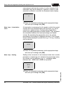
Meas. loop – Adjustment
Setup with the integrated indicating and adjustment unit
Units of measurement 1
m(d) ▼
The following illustrations and examples relate to the min./max.
adjustment of a radar sensor.
Min. adjustment 1
0.00 %
≙
32.00 m(d)
9.245 m(d)
à With [OK] you prepare the percentage value for editing,
with [–>] you set the cursor to the requested position. Set
the requested percentage value with [+] and save with
[OK]. The cursor jumps now to the distance value.
à Enter now the appropriate distance value in m [m(d)]
(corresponding to the percentage value) for the empty
vessel (e.g. distance from the sensor to the vessel bottom).
à Save the settings with [OK] and move to "Max. adjustment"
with [–>].
Max. adjustment 1
100.00 %
≙
0.000 m(d)
0.489 m(d)
à As previously described, enter now the percentage value
for the max. adjustment and confirm with [OK].
à Enter now the appropriate distance value in m [m(d)]
(corresponding to the percentage value) for the full vessel.
Keep in mind that the max. level must be below the radar
antenna.
à Finally save your settings with [OK], the adjustment is
28970-EN-050616
finished.
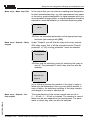
Meas. loop – Damping
To suppress fluctuation in the measured value display, e.g.
caused by an agitated product surface, an integration time can
be set. This time can be between 0 and 999 seconds. Keep in
mind, that this setting will increase the reaction time of the
VEGAMET 625 - Double channel Hart signal conditioning instrument
23
Setup with the integrated indicating and adjustment unit
measurement and that the reaction to quick changes of the
measured value will be delayed. In general, a time of a few
seconds is sufficient to smooth the measured value display.
Damping 1
1s
à Enter the requested parameter via the appropriate keys
and save your settings with [OK].
Meas. loop – Linearization
curve
A linearization is necessary for all vessels in which the vessel
volume does not increase linearly with the level, e.g. with a
cylindrical or spherical tank. Corresponding linearization
curves are preprogrammed for these vessels. They represent
the correlation between the level percentage and vessel
volume. By activating the appropriate curve, the volume
percentage of the vessel is displayed correctly. If the volume
should not be displayed in percent but e.g. in l or kg, a scaling
can be also set.
Linearization curve 1
linear ▼
à Enter the requested parameter via the appropriate keys
and save your settings with [OK].
Meas. loop – Scaling
Scaling is the conversion of the measured value into a certain
parameter or measuring unit. Instead of the percentage value,
the volume can be displayed, e.g. in l. Indicating values
between max. -99999 and +99999 are possible.
Scaling: Unit 1
Mass ▼
kg ▼
and save your settings with [OK].
24
VEGAMET 625 - Double channel Hart signal conditioning instrument
28970-EN-050616
à Enter the requested parameter via the appropriate keys
Setup with the integrated indicating and adjustment unit
Meas. loop – Meas. loop TAG
In this menu item you can enter an unambiguous designation
for each measurement loop, e.g. the measurement loop name
or the tank or product designation. In digital systems and in the
documentation of larger plants, a unique designation should be
entered for exact identification of individual measuring sites.
Meas. loop TAG 1
TAG-No. 1
à Enter the requested parameter via the appropriate keys
and save your settings with [OK].
Meas. loop – Outputs – Relay
outputs
Under "Outputs" you will find the relay and current outputs.
With relay output, first of all the requested mode ("Overfill
protection" or "Dry running protection") must be selected.
Relay operating mode 1
Overfill protection
à Enter now the switching points for switching the relay on
and off. The parameter to which they refer can also be
selected.
Relay switching points 1
Basic meas. value:
Percent ▼
In the following window the reaction of the relay in case of
failure can be determined. Here you can define whether, in
case of failure, the switching condition of the relay remains
unchanged or the relay is switched off.
28970-EN-050616
Meas. loop – Outputs – Current outputs
The characteristics of the current outputs can be set to
0 … 20 mA, 4 … 20 mA or inverted. The reaction in case of
failure can be also adapted to the requirements. The parameter to which they refer can also be selected.
VEGAMET 625 - Double channel Hart signal conditioning instrument
25
Setup with the integrated indicating and adjustment unit
Current output 1
Basic meas. value: % ▼
Characteristics: 4 … 20
mA ▼
Failure mode: 22 mA ▼
à Enter the requested parameter via the appropriate keys
and save your settings with [OK].
Display
In the menu item "Display", you can set the requested
displayed value for the measurement loop.
Displayed value
Percent ▼
à Enter the requested parameter via the appropriate keys
and save your settings with [OK].
Diagnostics
If the instrument displays a fault, further information can be
retrieved via the menu item "Diagnostics – Device status –
Add. information".
Sensor status
E007
Sensor type not compatible
Service
The service menu contains the following settings:
l
l
l
l
l
Simulation of the measured value
Reset
Set display language
PIN to block the menu
Change HART sensor address
à Enter the requested parameter via the appropriate keys
and save your settings with [OK].
Under this menu item you can assign and modify the HART
addresses of the connected sensors.
26
VEGAMET 625 - Double channel Hart signal conditioning instrument
28970-EN-050616
Service – Change sensor
address
Setup with the integrated indicating and adjustment unit
Note:
When addresses are being assigned, only one sensor with a
particular address must be connected on the bus. If this is not
the case, the sensor cannot be accessed and it is not possible
to assign an address.
Set the current HART address of the requested sensor in the
menu item "Previous address". The default setting of all
supplied VEGA sensors is always 00. After pushing the [–>]
key, you can assign the requested HART address in the range
of 01 – 15 in the menu "New address". Make sure that no
address is assigned twice.
Sensor address
New address:
01
Info
In the menu item "Info" the following information is available:
l
l
l
l
l
Additional adjustment and diagnostics options are available via
the Windows software PACTware™ and the suitable DTM.
Connection can be made via the interface converter VEGACONNECT or RS232/Ethernet (depending on the instrument
version). Further information is available in chapter "Parameter
adjustment with PACTware™, in the online help of
PACTware™ or the DTM as well as in the operating
instructions manual "RS232/Ethernet connection".
28970-EN-050616
Further settings
Sensor type and serial number
Date of manufacture and software version
Date of last change using PC
Details of VEGAMET 625
MAC address (with interface option Ethernet)
VEGAMET 625 - Double channel Hart signal conditioning instrument
27
Setup with the integrated indicating and adjustment unit
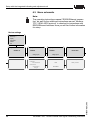
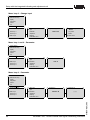
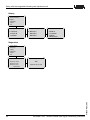
6.3 Menu schematic
Note:
The operating instructions manual "RS232/Ethernet connection" as well as the additional instructions manual "ModbusTCP, VEGA ASCII protocol" is attached to instructions with
RS232/Ethernet interface. Here you will find further information
for setup.
Device settings
▶
Device settings
Meas. loop
Display
Diagnostics
Service
Info
Application
Standard ▼
Input ②
undefined
undefined
Change input?
Host name
Device-TAG
Input ①
LAN/Internet
IP address:
192.168.200.200
Subnet Mask:
255.255.255.0
Change?
Device Name
Change input?
Communication protocol
Time/Date
15:34
VEGA protocol
18.09.2004
28970-EN-050616
28
VEGAMET 625 - Double channel Hart signal conditioning instrument
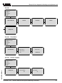
Setup with the integrated indicating and adjustment unit
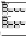
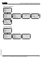
Meas. loop 1 and 2 – Input
▶
Device settings
Measurement loops
Display
Diagnostics
Service
Info
Measurement loops
▶
▶
Meas. loop 1
Meas. loop 2
Meas. loop 3
Meas. loop
Input
Parameter
Adjustment
Damping
Linearization curve
Sensor info ①
Input ①
Display now?
VEGAPULS (addr. 1)
Distance
Change input?
Sensor setting ①
Start sensor setting?
Meas. loop 1 and 2 – Change input
▶
Device settings
Measurement loops
Display
Diagnostics
Service
Info
Measurement loops
▶
Meas. loop 1
Meas. loop 2
Meas. loop 3
Sensor selection ①
Sensor search
List of sensors
Meas. loop
Input
Parameter
Adjustment
Damping
Linearization curve
Input ①
Sensor search
Sensor assignment ①
Searching…
VEGAPULS (addr. 1)
Distance
Input ①
▶
Sensor selection
Sensor value
Change input?
VEGAPULS addr. 1 ▼
28970-EN-050616
▶
▶
VEGAMET 625 - Double channel Hart signal conditioning instrument
29
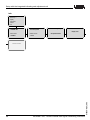
Setup with the integrated indicating and adjustment unit
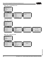
Meas. loop 3 – Change input
▶
Device settings
Measurement loops
Display
Diagnostics
Service
Info
Measurement loops
▶
▶
Meas. loop 1
Meas. loop 2
Meas. loop 3
Meas. loop ③
Input
Parameter
Adjustment
Damping
Linearization curve
Input variable ③
Sensor value
▶
Input variable ③
Percent
Lin. percent
Scaled
Sensor value
Meas. loop 1 and 2 – Parameter
▶
Device settings
Measurement loops
Display
Diagnostics
Service
Info
Measurement loops
▶
Meas. loop 1
Meas. loop 2
Meas. loop 3
▶
Meas. loop
Input
Parameter
Adjustment
Damping
Linearization curve
Parameter
Meas. loop
Input
Parameter
Adjustment
Damping
Linearization curve
Parameter ③
Level ▼
Meas. loop 3 – Parameter
▶
Device-TAG
Measurement loops
Display
Diagnostics
Service
Info
Measurement loops
▶
Meas. loop 1
Meas. loop 2
Meas. loop 3
▶
Difference ▼
Application ③
①-②
28970-EN-050616
30
VEGAMET 625 - Double channel Hart signal conditioning instrument
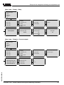
Setup with the integrated indicating and adjustment unit
Meas. loop – Adjustment
▶
Device settings
Measurement loops
Display
Diagnostics
Service
Info
Measurement loops
▶
Meas. loop 1
Meas. loop 2
Meas. loop 3
▶
Meas. loop
Input
Parameter
Adjustment
Damping
Linearization curve
Units of measurement ①
Meas. loop
Input
Parameter
Adjustment
Damping
Linearization curve
Damping ①
m(d) ▼
Min. adjustment ③
0.00 %
≙
32.00 m(d)
9.245 m(d)
Max. adjustment ③
100.00 %
≙
0.000 m(d)
0.489 m(d)
Meas. loop – Damping
▶
Device settings
Measurement loops
Display
Diagnostics
Service
Info
Measurement loops
Meas. loop 1
Meas. loop 2
Meas. loop 3
▶
1s
28970-EN-050616
▶
VEGAMET 625 - Double channel Hart signal conditioning instrument
31
Setup with the integrated indicating and adjustment unit
Meas. loop – Linearization curve
▶
Device settings
Measurement loops
Display
Diagnostics
Service
Info
Linearization curve ①
▶
Meas. loop
Input
Parameter
Adjustment
Damping
Linearization curve
Scaling: Unit ①
▶
Input
Parameter
Adjustment
Damping
Linearization curve
Scaling
Measurement loops
▶
Meas. loop 1
Meas. loop 2
Meas. loop 3
linear ▼
Meas. loop – Scaling
▶
Device settings
Measurement loops
Display
Diagnostics
Service
Info
Measurement loops
▶
Meas. loop 1
Meas. loop 2
Meas. loop 3
Scaling ①
0% = 0.5 kg
Mass
100% = 50.0 kg
kg
Meas. loop – Meas. loop TAG
▶
Device settings
Measurement loops
Display
Diagnostics
Service
Info
Measurement loops
▶
Meas. loop 1
Meas. loop 2
Meas. loop 3
▶
Input
Adjustment
Damping
Linearization curve
Scaling
Meas. loop TAG
Meas. loop TAG ①
TAG-No. 1
28970-EN-050616
32
VEGAMET 625 - Double channel Hart signal conditioning instrument
Setup with the integrated indicating and adjustment unit
Meas. loop – Output – Relay
▶
Device settings
Measurement loops
Display
Diagnostics
Service
Info
Measurement loops
▶
Meas. loop 1
Meas. loop 2
Meas. loop 3
▶
Relay operating mode 1
Overfill protection
Adjustment
Damping
Linearization curve
Scaling
Meas. loop TAG
Outputs
Outputs ①
▶
Relay outputs
Current outputs
Relay switching points 1
Relay switching points 1
Basic meas. value:
Percent
Switch point ON:
0%
Switch point OFF:
100%
Relay outputs ①
▶
Relay 1
Relay failure mode 1
Switch state:
Off
Meas. loop – Outputs – Current outputs
▶
Device settings
Measurement loops
Display
Diagnostics
Service
Info
Measurement loops
▶
Meas. loop 1
Meas. loop 2
Meas. loop 3
▶
Outputs ①
▶
Current output ①
Current output ①
▶
Basic meas. value
Output mode
Failure mode
Relay outputs
Current outputs
Current outputs ①
▶
Current output 1
Current output ①
▶
%
Lin%
28970-EN-050616
Basic meas. value: % ▼
Output mode: 4-20mA ▼
Failure mode: 22mA ▼
Adjustment
Damping
Linearization curve
Scaling
Meas. loop TAG
Outputs
VEGAMET 625 - Double channel Hart signal conditioning instrument
33
Setup with the integrated indicating and adjustment unit
Display
▶
Device settings
Measurement loops
Display
Diagnostics
Service
Info
Displayed value
Displayed value
▶
1 Percent ▼
2 Percent ▼
3 Scaled ▼
▶
Meas. loop 1
Meas. loop 2
Meas. loop 3
Displayed value
▶
Percent ▼
lin. percent ▼
Scaled ▼
Sensor value ▼
Diagnostics
▶
Device settings
Meas. loop
Display
Diagnostics
Service
Info
Sensor status
Meas. loop 1:E017
Meas. loop 2: OK
Meas. loop 3: OK
Show details?
Sensor status
E017
Adjustment span too small
28970-EN-050616
34
VEGAMET 625 - Double channel Hart signal conditioning instrument
Setup with the integrated indicating and adjustment unit
Service
▶
Device settings
Meas. loop
Display
Diagnostics
Service
Info
Reset
Simulation
Start simulation ▼
Language
Reset ▼
Deutsch ▼
PIN
Enable?
Sensor address
Change now?
Service – Simulation
▶
Device settings
Measurement loops
Display
Diagnostics
Service
Info
Simulation
Start simulation?
Simulation
▶
Sensor value 1
Sensor value 2
Both
Simulation
Sensor value 1
+000.00 m(d)
Service – Sensor address
▶
Device settings
Measurement loops
Display
Diagnostics
Service
Info
28970-EN-050616
Sensor address
Change now?
Sensor address
Sensor address
Previous address:
00
New address:
01
VEGAMET 625 - Double channel Hart signal conditioning instrument
35
Setup with the integrated indicating and adjustment unit
Info
▶
Device settings
Meas. loop
Display
Diagnostics
Service
Info
Sensor type
VEGAMET 625
Date of manufacture
03. February 2004
Serial number
12345678
Software version
1.11.00
Date of last change using PC
VEGAMET details
Display now?
26. September 2004
MAC address
00:30:87:D7:E8:E7
28970-EN-050616
36
VEGAMET 625 - Double channel Hart signal conditioning instrument
Setup with PACTware™
7 Setup with PACTware™
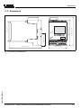
7.1 Connecting the PC
Connecting the PC via VEGACONNECT
For temporary connection of the PC, e.g. for parameter
adjustment, the connection can be made via the interface
converter VEGACONNECT. The necessary I²C interface in the
front of VEGAMET 625 is available with all instrument
versions. On the computer, connection is made via the RS232
interface. If this is not available on your PC or already
occupied, it is also possible to use a USB – RS232 adapter (e.
g. article no. 2.26900).
3
2
VEGACONNECT 3
Fig.
1
2
3
28970-EN-050616
Connection of the PC via
RS232
PACTwareTM/
VEGA-DTM
1
6: Connection via VEGACONNECT
RS232 interface of the PC
I²C adapter cable for VEGACONNECT 3 (article no. 2.27323)
VEGAMET 625
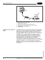
Via the RS232 interface, direct parameter adjustment and
measured value enquiry of the instrument can be carried out
via PACTware™. Use the RS232 modem connection cable
that is supplied with the instrument and an additionally
connected interlink cable (e.g. article no. LOG571.17347). To
reduce EMC interference, you should mount the supplied
ferrite bead on the RS232 modem connection cable.
If there is no RS232 interface on the PC or if the interface is
already occupied, it is also possible to use a USB – RS232
adapter (e.g. article no. 2.26900).
VEGAMET 625 - Double channel Hart signal conditioning instrument
37
Setup with PACTware™
5
4
PACTwareTM/
VEGA-DTM
3
2
Fig.
1
2
3
4
5
1
7: Connection of the PC via RS232
RS232 interface of the PC
RS232 interlink cable (article no. LOG571.17347)
RS232 modem connection cable (in the scope of delivery)
RS232 interface of VEGAMET 625
VEGAMET 625
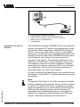
The RS232 interface is particularly suitable for easy modem
connection. For this purpose, external analogue, ISDN and
GSM modems with standard interface can be used. The
necessary RS232 modem connection cable is supplied with
VEGAMET 625 To reduce EMC interference, you should
mount the supplied ferrite bead on the RS232 modem
connection cable. Remote enquiry and processing of the
measured values is now possible via the software
"Visual VEGA". Alternatively, independent, time or eventcontrolled transmission of measured values via e-mail is also
possible. In addition, a remote parameter adjustment of
VEGAMET 625 and the connected sensors is possible with
PACTware™.
38
VEGAMET 625 - Double channel Hart signal conditioning instrument
28970-EN-050616
Connection of the modem via
RS232
Setup with PACTware™
4
3
2
Fig.
1
2
3
4
Connection of the PC via
Ethernet
1
8: Connection of the modem via RS232
Analogue, ISDN or GSM modem with RS232 interface
RS232 modem connection cable (in the scope of delivery)
RS232 interface of VEGAMET 625
VEGAMET 625
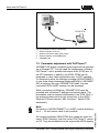
With the Ethernet interface, VEGAMET 625 can be connected
directly to an existing PC network. Any standard patch cable
can be used. When connecting a VEGAMET 625 directly to
the PC, a cross-over cable must be used. To reduce EMC
interference, you should mount the supplied ferrite bead on the
Ethernet connection cable. Each VEGAMET 625 then gets its
own IP address under which it can be accessed from
anywhere in the network. The parameter adjustment of the
instrument via PACTware™ can be carried out from any PC.
The measured values can be made available to individual
users within the company network as HTML chart. Alternatively, independent, time or event-controlled transmission of
measured values via e-mail is also possible.
28970-EN-050616
For more comprehensive requirements, we recommend using
the software " Visual VEGA " for measured value enquiry and
visualisation.
Note:
To adjust with PACTware™ and DTM, a suitable IP address
must be available in the instrument. Each instrument is preset
to address 192.168.200.200. Enter the address and subnet
mask corresponding to your network directly via the keyboard.
Briefly interrupt the power supply, then the instrument is
accessible via its IP address everywhere in the network. In
addition, this information must be entered in the DTM (see
chapter "Parameter adjustment with PACTware™").
VEGAMET 625 - Double channel Hart signal conditioning instrument
39
Setup with PACTware™
4
3
PACTwareTM/
VEGA-DTM
2
1
Fig.
1
2
3
4
9: Connection of the PC via Ethernet
Ethernet interface of the PC
Ethernet connection cable (patch cable)
Ethernet interface of VEGAMET 625
VEGAMET 625
7.2 Parameter adjustment with PACTware™
VEGAMET 625 signal conditioning instrument can be operated
via a Windows PC. You will need the configuration software
PACTware™ and a suitable instrument driver (DTM) acc. to
the FDT standard. In addition, the VEGA DTMs can be
integrated in other frame applications acc. to FDT standard.
For connection either the interface converter VEGACONNECT
or one of the offered interfaces (Ethernet/RS232) in VEGAMET
625 is required. Not only VEGAMET 625 itself, but also
connected VEGA HART sensors can be accessed.
When connecting via Ethernet, VEGAMET 625 must be
provided with a suitable IP address and subnet mask. This
information must be entered additionally in the DTM. Click in
the project window with the right mouse key to the VEGA
Ethernet DTM and choose "Add. functions – Modify DTM
addresses").
Note:
Connection of VEGACONNECT or a HART modem directly to
the 4 … 20 mA sensor cable is not possible.
40
VEGAMET 625 - Double channel Hart signal conditioning instrument
28970-EN-050616
All currently available VEGA DTMs are combined under the
name "DTM Collection" with the current PACTware™ version
on CD. They are available from the responsible VEGA agency
Setup with PACTware™
for a token fee. The basic version of this DTM Collection incl.
PACTware™ is available as a free-of charge download from
our homepage "www.vega.com".
The professional version also includes saving and printing of
project documentation. A DTM licence for the appropriate
instrument family can be purchased from the responsible
VEGA agency.
Further setup steps are described in the operating instructions
manual "DTM-Collection/PACTware™" attached to each CD
and which can also be downloaded from the Internet. A
detailed description is available in the online help of
PACTware™ and the VEGA DTMs as well as in the operating
instructions manual "RS232/Ethernet connection".
Information:
Keep in mind that for setup of VEGAMET 625, DTM-Collection
04/2004 or a newer version must be used.
7.3 Setup web server/e-mail, remote enquiry
28970-EN-050616
The setup and application examples of the web server, e-mail
functions as well as Modbus TCP are listed in the separate
operating instructions manual "RS232/Ethernet connection".
This manual is attached to each instrument with RS232 or
Ethernet interface. There you will also find the visualisation and
remote enquiry with the "Visual VEGA" software.
VEGAMET 625 - Double channel Hart signal conditioning instrument
41
Application examples
8 Application examples
8.1 Interface measurement with VEGAFLEX 67
In an interface measurement, there are two different media
which do not mix, e.g. water and oil or solvents. To detect the
volume of both products, it is necessary to detect the height of
the upper liquid (level) and the interface between the two
products. A VEGAFLEX 67 is necessary as a transmitter which
delivers the distance to the upper medium as well as the
distance to the interface. Via the adjustment in VEGAMET 625
the level, interface and layer thickness of the upper medium
can be calculated and displayed.
The following steps are necessary:
l
Selection of the application
- Select under "Device settings – Application" the entry
"Interface measurement" and confirm with [OK]. Via the
[–>] key you reach the next step.
l
Assignment of the inputs and measurement loops
- Select "Input – Change input". Now an automatic
sensor search is started and, if there is a proper
connection, VEGAFLEX 67 will be displayed. Accept
the settings with [OK] and move to the DK value input
with [–>]. The input variables are automatically assigned to the following measurement loops:
-
l
l
Input of the DK value
Enter the exact DK value of the upper medium. For
further information on the DK value, see the operating
instructions manual of VEGAFLEX 67.
-
Adjustment
- Each VEGAFLEX 67 is supplied with default settings.
The values of this adjustment are automatically transferred to VEGAMET 625 when creating an interface
measurement. Normally, a manual adjustment is not
necessary. Should the instrument get a special
adjustment, this adjustment can be carried out under
"Meas. loops – Adjustment". Keep in mind that this
adjustment must be carried out for all three measurement loops separately.
VEGAMET 625 - Double channel Hart signal conditioning instrument
28970-EN-050616
42
Meas. loop 1: Interface (level of the lower medium)
Meas. loop 2: Level (total level of both products)
Meas. loop 3: Layer thickness (thickness of the upper
medium)
Application examples
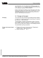
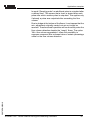
1
d2
d1
L2
h2
TS
L1
h1
Fig.
1
d1
d2
TS
h1
h2
L1
L2
10: Interface measurement
Reference plane
Distance to the interface, meas. loop 1
Distance to the level, meas. loop 2
Thickness of the upper medium (d1-d2), meas. loop 3 (displayed value)
Height - Interface (displayed value)
Height - Level (displayed value)
Lower medium
Upper medium
8.2 Flow measurement
Physical principle
For flow measurement in open flumes, a contraction or
standardised flume must be used. Depending on the flow
volume, this contraction generates a certain backwater. The
flow can be determined from the height of this backwater. The
flow volume is outputted by an appropriate number of pulses
on the relay or current output.
Flume
Depending on the type and version, each flume generates a
different backwater. The data of the following flumes are
available in the instrument:
l
l
28970-EN-050616
l
Palmer-Bowlus-Flume
Venturi flume, trapezoidal weir, rectangular weir
V-Notch
Setup
The configuration of the flow measurement loop requires
PACTware™ with the suitable DTMs. The example refers to a
flow measurement with a radar sensor. The following setup
steps must be carried out:
l
l
Selection of the parameter "Flow"
Carrying out adjustment
VEGAMET 625 - Double channel Hart signal conditioning instrument
43
Application examples
l
l
l
Select flume (Linearization)
Set scaling
Parameter adjustment of pulse outputs
Parameter – Flow
Select in the DTM window "Parameter" the option "Flow" with
the requested unit of measurement.
Adjustment
Min. adjustment: Enter the suitable value for 0 %, i.e. the
distance from the sensor to the medium as long as there is no
flow. These are in the following example 1.40 m.
Max. adjustment: Enter the suitable value for 100 %, i.e. the
distance from the sensor to the medium, with the max. flow
volume. This is in the following example 0.80 m.
100% = 0,80m (d) = 400m3/h
0% = 1,40m (d) = 0m3/h
Fig. 11: Adjustment flow measurement with V-notch
Linearization curve
Select in the DTM window "Linearization" the option "Flow"
and then the used flume (in the above example V-notch).
Scaling
Select in the DTM window "Scaling" under "Parameter" the
option "Flow". Finally the allocation of a value must be carried
out, i.e. the flow volume is assigned to the 0 and 100 % value.
As the last step, select the requested meas. unit. For above
example: 0 % = 0 and 100 % = 400, meas. unit m³/h.
Outputs
First of all decide if you want to use a relay and/or a current
output. In the DTM window "Outputs" you can use any of the
three outputs as long as these are not yet used for other tasks.
44
VEGAMET 625 - Double channel Hart signal conditioning instrument
28970-EN-050616
Finally select under "Mode" (relay) or "Output characteristics"
(current output) the option "Flow volume pulse" or "Sampling
pulse". Enter under "Pulse output all" the flow volume after
which a pulse should be outputted (e.g. 400 m³ corresponds to
one pulse per hour with a flow volume of 400 m³/h).
Application examples
In mode "Sampling pulse" an additional pulse is outputted after
a defined time. This means that a timer is started after each
pulse after which another pulse is outputted. This applies only
if already a pulse was outputted after exceeding the flow
volume.
28970-EN-050616
Due to sludge at the bottom of the flume, it can happen that the
min. adjustment originally carried out can no longer be
reached. Therefore small quantities will continuously enter the
flow volume detection despite the "empty" flume. The option
"Min. flow volume suppression" offers the possibility to
suppress measured flow volumes below a certain percentage
value for the flow volume detection.
VEGAMET 625 - Double channel Hart signal conditioning instrument
45
Maintenance and fault rectification
9 Maintenance and fault rectification
9.1 Maintenance
When used as directed in normal operation, VEGAMET 625 is
completely maintenance-free.
9.2 Fault rectification
Causes of malfunction
VEGAMET 625 offers maximum reliability. Nevertheless faults
can occur during operation. These may be caused by the
following, e.g.:
l
l
l
Measured value of the sensor not correct
Power supply
Interference on the cables
Fault rectification
The first measures to be taken are to check the input/output
signals as well as to evaluate the error messages via the
display. The procedure is described below. Further comprehensive diagnostics can be carried out on a PC with the
software PACTware™ and the suitable DTM. In many cases,
the causes can be determined in this way and faults can be
rectified.
24 hour service hotline
Should these measures not be successful, please call in
urgent cases the VEGA service hotline under the phone
number +49 1805 858550.
The hotline is available to you 7 days a week round-the-clock.
Since we offer this service world-wide, the support is only
available in the English language. The service is free of
charge, only the standard telephone costs will be charged.
Fault messages
?
E003
l CRC-error
à Carry out a reset
à Return instrument for repair
?
E007
à Search for the sensor and allocate it under "Meas. loop
– Input"
46
VEGAMET 625 - Double channel Hart signal conditioning instrument
28970-EN-050616
l Sensor type not compatible
Maintenance and fault rectification
?
E008
l Sensor not found
à Check connection of the sensor
à Check HART address of the sensor
?
E013
l Sensor signals failure/no valid measured value
à Check sensor parameter adjustment
à Return sensor for repair
?
E016
l Empty/full adjustment reversed
à Carry out a fresh adjustment
?
E017
l Adjustment span too small
à Carry out a fresh adjustment and increase the distance
between min. and max. adjustment
?
E021
l Scaling span too small
à Carry out a fresh scaling, increase the distance
between min. and max. scaling.
?
E026
l Units of the input variable are different (only differential
measurement loop)
28970-EN-050616
à Adapt the units of both
à Use sensors with the same input variable
VEGAMET 625 - Double channel Hart signal conditioning instrument
47
Maintenance and fault rectification
?
E030
l Invalid measured value
à Check sensor parameter adjustment
?
E034
l EEPROM defective
à Carry out a reset
à Return instrument for repair
?
E035
l EEPROM CRC-error
à Carry out a reset
à Return instrument for repair
?
E036
l Instrument software not executable (during software
update or after failed update)
à wait until software update is finished
à Carry out another software update
?
E053
l Sensor measuring range not read correctly
à HART communication error: Check sensor cable and
screening
?
E062
l Pulse priority too small
à Increase under "Output" th entry "Pulse output all" so
that max. one pulse per second is outputted.
28970-EN-050616
48
VEGAMET 625 - Double channel Hart signal conditioning instrument
Maintenance and fault rectification
?
E110
l Span between relay switching points too small
à Increase the distances between the relay switching
points
?
E111
l Relay switching points interchanged
à Change relay switching points for "On/Off"
9.3 Instrument repair
If it is necessary to repair VEGAMET 625 please proceed as
follows:
You can download a return form (23 KB) from our homepage
www.vega.com under: "Services – Downloads – Forms and
Certificates – Repair form".
By doing this you help us carry out the repair quickly and
without having to call back for needed information.
l
l
l
28970-EN-050616
l
Print and fill out one form per instrument
Clean the instrument and pack it damage-proof
Attach the completed form and possibly also a safety data
sheet to the instrument.
Send the instrument to the respective address of your
agency. In Germany to the VEGA headquarters in
Schiltach.
VEGAMET 625 - Double channel Hart signal conditioning instrument
49
Dismounting
10 Dismounting
10.1 Dismounting procedure
Warning:
Before dismounting, be aware of dangerous process conditions such as e.g. pressure in the vessel, high temperatures,
corrosive or toxic products etc.
Take note of chapters "Mounting" and "Connecting to power
supply" and carry out the listed steps in reverse order.
10.2 Disposal
VEGAMET 625 consists of materials which can be recycled by
specialised recycling companies. We have purposely designed the electronic modules to be easily separable. Mark the
instrument as scrap and dispose of it according to government
regulations (electronic scrap ordinance, …).
Materials: see "Technical data"
If you cannot dispose of the instrument properly, please
contact us about disposal methods or return.
28970-EN-050616
50
VEGAMET 625 - Double channel Hart signal conditioning instrument
Supplement
11 Supplement
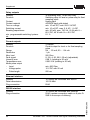
11.1 Technical data
General data
Series
Dimensions
Weight
Housing materials
Socket materials
Screw terminals
module unit with plug-in socket for mounting on
carrier rail 35x7.5 acc. to EN 50022
W = 72 mm (2.83 in), H = 118.5 mm (4.66 in), D
= 134 mm (5.28 in)
approx. 500 g (1.10 lbs)
Noryl SE100, Lexan 920A
Noryl SE100, Noryl SE1 GFN3
max. wire cross section 1.5 mm²
Power supply
Operating voltage
Power consumption
20 … 253 V AC/DC, 50/60 Hz
12 VA; 7.5 W (10 VA; 5.5 W with Ex)
Sensor input
Number of sensors
Kind of input (selectable)
- active input
2x VEGA HART sensors
-
sensor has own power supply
passive input
sensor is powered by VEGAMET 625
Measured value transmission
- HART protocol (Multidrop)
digital for VEGA HART sensors
Terminal voltage
- non-Ex version
approx. 28 V with 2 sensors (8 mA)
-
approx. 18 V with 2 sensors (8 mA)
Ex version
Current limitation
Adjustment range HART sensor
- Adjustment range
±10 % of sensor measuring range
-
0.1 % of sensor measuring range
min. adjustment delta
2-wire screened standard cable
28970-EN-050616
Connection cable
approx. 45 mA (approx. 26 mA with Ex)
VEGAMET 625 - Double channel Hart signal conditioning instrument
51
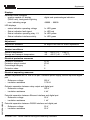
Supplement
Relay outputs
Quantity
Function
Contact
Contact material
Turn-on voltage
Switching current
Breaking capacitance
min. programmable switching hysteresis
3x operating relay, 1x fail safe relay
Switching relay for level or pulse relay for flow/
sampling pulse
floating spdt
AGSNO2 hard gold-plated
min. 10 mV DC, max. 250 V AC/DC
min. 10 µA DC, max. 3 A AC, 1 A DC
min. 50 mW, max. 750 VA, 18 W with U =
60 V DC; 40 W with U<= 40 V DC
0.1 %
Current outputs
Quantity
Function
Range
Resolution
Max. load
Fault signal
Linearity error
Temperature error
Mode pulse output
- Load
3 outputs
Current output for level or for flow/sampling
pulse
0/4 … 20 mA; 20 … 0/4 mA
1 µA
500 Ohm
0; 3.6; 4; 20; 20.5, 22 mA (adjustable)
0.08 % (relating to 20 mA)
0.005 %/K (relating to 20 mA)
min. 600 Ohm
-
Voltage pulse
12 V DC with 20 mA
-
Pulse length
200 ms
Ethernet interface
Quantity
Data transmission
Plug connection
1x, cannot be combined with RS232
10/100 Mbit
RJ45
RS232 interface
Quantity
Plug connection
1x, cannot be combined with Ethernet
RJ45 (modem connection cable on 9-pole DSUB in the scope of delivery)
28970-EN-050616
52
VEGAMET 625 - Double channel Hart signal conditioning instrument
Supplement
Displays
Measured value indication
- graphic-capable LC display
(50x25 mm), background lightning
digital and quasianalogue indication
-
-99999 ... 99999
max. indicating range
LED displays
- status indication operating voltage
1x LED green
-
Status indication fault signal
1x LED red
-
Status indication operating relay 1-3
3x LED yellow
-
Status indication interface activity
1x LED green
Adjustment
Adjustment elements
4x keys in the front for menu adjustment
Ambient conditions
Ambient temperature
Storage and transport temperature
-20 … +60°C (-4 … +140°F)
-40 … +80°C (-40 … +176°F)
Electrical protective measures
Protection instrument
Protection plug-in socket
Overvoltage category
Protection class
IP 30
IP 20
II
II
Electrical separating measures
Reliable separation acc. to VDE 0106 part 1 between power supply, sensor input and digital
part
- Reference voltage
250 V
-
insulation resistance
3.75 kV
Galvanic separation between relay output and digital part
- Reference voltage
250 V
-
insulation resistance
4 kV
Potential separation between Ethernet interface and digital part
- Reference voltage
50 V
28970-EN-050616
-
insulation resistance
1 kV
Potential separation between RS232 interface and digital part
- Reference voltage
50 V
-
insulation resistance
50 V
VEGAMET 625 - Double channel Hart signal conditioning instrument
53
Supplement
Approvals1)
ATEX II (1) GD, [EEx ia] IIC
54
Deviating data with Ex applications: see separate safety instructions.
VEGAMET 625 - Double channel Hart signal conditioning instrument
28970-EN-050616
1)
Supplement
11.2 Dimensions
3
4
5
6
7
8
COM
55mm (2 11/64")
ESC
OK
119mm (4 11/16")
2
110mm (4 21/64")
87mm (3 27/64")
1
on
Ser. No.
12345678
9 10
17 18
130mm (5 1/8")
11 12
20 21 22
13 14
15 16
23 24 25 26 27 28
72mm (2 53/64")
28970-EN-050616
Fig. 12: Dimensions VEGAMET 625
VEGAMET 625 - Double channel Hart signal conditioning instrument
55
11.3 Certificate
CE declaration of conformity
28970-EN-050616
Fig. 13: CE declaration of conformity
56
VEGAMET 625 - Double channel Hart signal conditioning instrument
28970-EN-050616
VEGAMET 625 - Double channel Hart signal conditioning instrument
57
28970-EN-050616
58
VEGAMET 625 - Double channel Hart signal conditioning instrument
28970-EN-050616
VEGAMET 625 - Double channel Hart signal conditioning instrument
59
VEGA Grieshaber KG
Am Hohenstein 113
77761 Schiltach
Germany
Phone +49 7836 50-0
Fax +49 7836 50-201
E-mail: [email protected]
www.vega.com
ISO 9001
All statements concerning scope of delivery, application,
practical use and operating conditions of the sensors and
processing systems correspond to the information available at the time of printing.
Technical data subject to alterations
28970-EN-050616