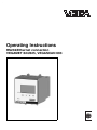
1
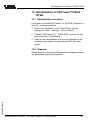
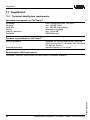
Operating Instructions
RS232/Ethernet connection
VEGAMET 624/625, VEGASCAN 693
Contents
Contents
1
About this document
1.1
1.2
1.3
2
4.2
7.3
.
.
.
.
.
.
.
.
.
.
.
.
.
.
.
.
.
.
.
.
.
.
.
.
.
.
.
.
.
.
.
.
.
.
.
.
.
.
.
.
..
..
..
..
..
5
5
5
5
5
.
.
.
.
.
.
.
.
.
.
.
.
.
.
.
.
.
.
.
.
.
.
.
.
.
.
.
.
.
.
.
.
.
.
.
.
.
.
.
.
.
.
.
.
.
.
.
.
.
.
.
.
..
..
..
..
6
6
6
7
System requirements for
PACTware™installation . . . . . . . . . . . . . . . . . .
Installation of PACTware™ and DTM . . . . . . . .
8
8
Configuration. . . . . . .
Principle of operation .
Adjustment . . . . . . . .
Storage and transport
.
.
.
.
.
.
.
.
.
.
.
.
.
.
.
.
Connection requirements . . . . . . . . . . . . . . . . .
Connection to PC/network/modem . . . . . . . . . .
9
9
Start PACTware™ . . . . . . . . . . . . . . . . . . . . . 13
Creating a project . . . . . . . . . . . . . . . . . . . . . . 13
Parameter adjustment . . . . . . . . . . . . . . . . . . . 15
Possible application areas . . . . . . . . . . . . . . . . 17
Stock management of a tank farm via network
and web browser. . . . . . . . . . . . . . . . . . . . . . . 17
Remote enquiry of several tank farms via
modem . . . . . . . . . . . . . . . . . . . . . . . . . . . . . . 18
General. . . . . . . . . . . . . . . . . . . . . . . . . . . . . . 20
RS232/Ethernet connection - VEGAMET 624/625, VEGASCAN 693
30325-EN-050616
PC/DCS values
8.1
2
.
.
.
.
.
Application examples
7.1
7.2
8
.
.
.
.
.
Adjustment with PACTware™
6.1
6.2
6.3
7
.
.
.
.
.
Connection
5.1
5.2
6
.
.
.
.
.
Installation
4.1
5
.
.
.
.
.
Authorised personnel . . . . .
Appropriate use. . . . . . . . .
Warning about misuse . . . .
General safety instructions .
Environmental instructions .
Product description
3.1
3.2
3.3
3.4
4
4
4
4
For your safety
2.1
2.2
2.3
2.4
2.5
3
Function . . . . . . . . . . . . . . . . . . . . . . . . . . . . .
Target group . . . . . . . . . . . . . . . . . . . . . . . . . .
Symbolism used . . . . . . . . . . . . . . . . . . . . . . .
Contents
9
Measured value enquiry via web browser
9.1
9.2
9.3
General. . . . . . . . . . . . . . . . . . . . . . . . . . . . . . 22
Measured value enquiry via Ethernet . . . . . . . . 22
Measured value enquiry via RS232 (PPP). . . . . 23
10 Measured value transmission via e-mail
10.1
10.2
10.3
10.4
10.5
General. . . . . . . . . . . . . . . . . . . . . . . . . . . . . .
E-mail transmission via network and mail server.
E-mail transmission via modem/Dial-up . . . . . . .
Description of the measurement data files. . . . .
Status file . . . . . . . . . . . . . . . . . . . . . . . . . . . .
27
28
30
33
36
11 Maintenance and fault rectification
11.1 Maintenance/Update . . . . . . . . . . . . . . . . . . . . 46
11.2 Fault rectification . . . . . . . . . . . . . . . . . . . . . . . 46
12 Deinstallation of PACTware™/VEGA DTMs
12.1 Deinstallation procedure. . . . . . . . . . . . . . . . . . 47
12.2 Disposal . . . . . . . . . . . . . . . . . . . . . . . . . . . . . 47
13 Supplement
30325-EN-050616
13.1 Technical data/System requirements. . . . . . . . . 48
RS232/Ethernet connection - VEGAMET 624/625, VEGASCAN 693
3
About this document
1 About this document
1.1 Function
This operating instructions manual has all the information you
need for quick setup and safe operation. Please read this
manual before you start setup.
1.2 Target group
This operating instructions manual is directed to trained
personnel. The contents of this manual should be made
available to these personnel and put into practice by them.
1.3 Symbolism used
Information, tip, note
This symbol indicates helpful additional information.
Caution, warning, danger
This symbol informs you of a dangerous situation that could
occur. Ignoring this cautionary note can impair the person and/
or the instrument.
Ex applications
This symbol indicates special instructions for Ex applications.
l
List
The dot set in front indicates a list with no implied sequence.
à
Action
This arrow indicates a single action.
1
Sequence
Numbers set in front indicate successive steps in a procedure.
30325-EN-050616
4
RS232/Ethernet connection - VEGAMET 624/625, VEGASCAN 693
For your safety
2 For your safety
2.1 Authorised personnel
All operations described in this operating instructions manual
must be carried out only by trained specialist personnel
authorised by the operator. For safety and warranty reasons,
any internal work on the instruments must be carried out only
by personnel authorised by the manufacturer.
2.2 Appropriate use
VEGAMET 624/625 and VEGASCAN 693 are universal signal
conditioning and power supply units for connection of
4 … 20 mA/HART sensors. Through the optionally integrated
RS232 or Ethernet interface they are particularly suitable for
connection to networks and for remote enquiry.
2.3 Warning about misuse
Inappropriate or incorrect use of the instrument can give rise to
application-specific hazards, e.g. vessel overfill or damage to
system components through incorrect mounting or adjustment.
2.4 General safety instructions
Installation and use of the software are carried out at your own
risk. We do not accept liability for consequential damage.
2.5 Environmental instructions
Protection of the environment is one of our most important
duties. That is why we have introduced an environment
management system with the goal of continuously improving
company environmental protection. The environment management system is certified acc. to DIN EN ISO 14001.
Please help us fulfil this obligation by observing the environmental instructions in this manual:
l
Chapter "Storage and transport"
Chapter "Disposal"
30325-EN-050616
l
RS232/Ethernet connection - VEGAMET 624/625, VEGASCAN 693
5
Product description
3 Product description
3.1 Configuration
All VEGAMET 624/625 and VEGASCAN 693 can be equipped
with either the RS232 or Ethernet interface. These interfaces
are permanently integrated in the instrument - retrofitting or
exchanging is thus not possible. Connection is made via an
RJ-45 plug on the bottom side of the applied instrument.
3.2 Principle of operation
Area of application
RS232 interface
The RS232 interface is suitable for simple modem connection
to PACTware™ or " Visual VEGA ". External analogue, ISDN
and GSM modems can be used for this purpose.
Ethernet interface
With the Ethernet interface, instruments can be connected
directly to an existing PC network. An own IP address is
assigned to each instrument, under which it can be reached
from everywhere in the network.
3.3 Adjustment
To adjust the instrument, the configuration software
PACTware™ and a suitable instrument driver (DTM) acc. to
FDT standard are required. In addition, the VEGA DTMs can
be integrated in other frame applications acc. to FDT standard.
As an alternative, adjustment of the basic functions is possible
via the integrated indicating and adjustment module.
All currently available VEGA DTMs are provided in a DTM
Collection with the current PACTware™version on CD. This
CD is available from an authorised VEGA agency for a token
fee. The basic version of this DTM Collection incl.
PACTware™ is also available as a free-of-charge download
from the Internet. The professional version also includes
saving and printing of project documentation. A DTM licence
for the respective instrument family can be purchased via the
responsible VEGA agency.
30325-EN-050616
6
RS232/Ethernet connection - VEGAMET 624/625, VEGASCAN 693
Product description
3.4 Storage and transport
The packaging consists of easily separable monomaterials.
These materials are environment-friendly and recyclable.
Dispose of the packaging material via specialised recycling
companies.
Storage and transport conditions
No special storage and transport conditions are necessary.
30325-EN-050616
Packaging
RS232/Ethernet connection - VEGAMET 624/625, VEGASCAN 693
7
Installation
4 Installation
4.1 System requirements for
PACTware™installation
General
Pentium 500 MHz or higher, min. 128 MB RAM, 200 MB free
memory, Windows XP/2000/ME/NT 4.0, Internet Explorer 5.0
or higher, graphic resolution 1024x768 or higher, Microsoftcompatible mouse, RS232/Ethernet interface (see also
"Technical data" in the "Supplement").
Windows NT/2000/XP
To install the software under Windows NT/2000/XP you will
need administrator rights. Remember that the installation is
complete only after a restart of the computer, and thus a login
with administrator rights is again necessary.
4.2 Installation of PACTware™ and DTM
Before installation, all running programs should be exited.
2
Insert the CD, the installation program will be started
automatically. If the CD does not start automatically, the
installation can be started by a double click to the file
"autorun.exe" If PACTware™ was downloaded from the
Internet, this file must be unpacked first and then be
installed via "autorun.exe".
3
Select the desired program components and start the
installation of the individual programs one after the other.
The installation of PACTware™ without selecting the DTM
Collection is not recommended, without a DTM, the
parameter adjustment of an instrument is not possible. The
installation of the " HART-Protocol-Driver " is only
necessary if instruments of other manufacturers are used.
4
Now follow the instructions of the installation assistant. In
rare cases, a message may appear during installation
informing you that a DLL file is in use and cannot be
copied. In this case, continue with the installation by
pushing "Ignore".
5
At the end of the installation a window opens in which you
can enter the licence number of your software product
certificate (for the purchased Professional Version). If you
want to use the DTM in the basic version, you can exit this
window by pushing the button "Cancel".
RS232/Ethernet connection - VEGAMET 624/625, VEGASCAN 693
30325-EN-050616
8
1
Connection
5 Connection
5.1 Connection requirements
First of all, the connection to power supply and sensor must be
carried out as described in the respective operating instructions manual.
5.2 Connection to PC/network/modem
Connection of the PC via
RS232
Via the RS232 interface, direct parameter adjustment and
measured value enquiry of the instrument can be carried out
via PACTware™. Use the RS232 modem connection cable
that is supplied with the instrument and an additionally
connected interlink cable (e.g. article no. LOG571.17347). To
reduce EMC interference, you should mount the supplied
ferrite bead on the RS232 modem connection cable.
If there is no RS232 interface on the PC or if the interface is
already occupied, it is also possible to use a USB – RS232
adapter (e.g. article no. 2.26900).
5
4
PACTwareTM/
VEGA-DTM
3
2
30325-EN-050616
Fig.
1
2
3
4
Connection of the modem via
RS232
1
1: Connection of the PC via RS232
RS232 interface of the PC
RS232 interlink cable (article no. LOG571.17347)
RS232 modem connection cable (in the scope of delivery)
RS232 interface to the signal conditioning instrument
The RS232 interface is particularly suitable for easy modem
connection. For this purpose, external analogue, ISDN and
GSM modems with standard interface can be used. The
necessary RS232 modem connection cable is included with
RS232/Ethernet connection - VEGAMET 624/625, VEGASCAN 693
9
Connection
the delivery. To reduce EMC interference, you should mount
the supplied ferrite bead on the RS232 modem connection
cable. Remote enquiry and processing of the measured values
is now possible via the software " Visual VEGA ". As an
alternative, the independent, time or event-controlled transmission of measured values via e-mail is also possible. In
addition, a remote parameter adjustment of the signal
conditioning instrument and the connected sensors is possible
with PACTware™.
4
3
2
Fig.
1
2
3
Connection of the PC via
Ethernet
1
2: Connection of the modem via RS232
Analogue, ISDN or GSM modem with RS232 interface
RS232 modem connection cable (in the scope of delivery)
RS232 interface to the signal conditioning instrument
With the Ethernet interface, each instrument can be connected
directly to an existing PC network. Any standard patch cable
can be used. A cross-over cable must be used when
connecting directly to the PC. To reduce EMC interference,
you should mount the supplied ferrite bead on the Ethernet
cable. Each instrument gets its own IP address under which it
can be accessed from anywhere in the network. The parameter adjustment of the instrument via PACTware™ can be
carried out from any PC. The measured values can be made
available to individual users within the company network
through HTTP access as HTML chart. As an alternative, also
the independent, time or event-controlled transmission of
measured values via e-mail is possible.
10
RS232/Ethernet connection - VEGAMET 624/625, VEGASCAN 693
30325-EN-050616
For more comprehensive requirements, we recommend using
the software " Visual VEGA " for measured value enquiry and
visualisation.
Connection
Note:
To adjust with PACTware™ and DTM, a suitable IP address
must be available in the instrument. Each instrument is preset
to address 192.168.200.200. Enter the address and subnet
mask corresponding to your network directly via the keyboard.
Briefly interrupt the power supply, then the instrument is
accessible via its IP address everywhere in the network. In
addition, this address must be entered in the DTM (see
chapter "Parameter adjustment with PACTware™").
4
3
PACTwareTM/
VEGA-DTM
2
1
Fig.
1
2
3
For temporary connection of the PC, e.g. for parameter
adjustment, the connection can be made via the interface
converter VEGACONNECT. The necessary I²C interface in the
front of VEGAMET/VEGASCAN is available with all instrument
versions. On the computer, connection is made via the RS232
interface. If this is not available on your PC or already
occupied, it is also possible to use a USB – RS232 adapter (e.
g. article no. 2.26900).
30325-EN-050616
Connecting the PC via VEGACONNECT
3: Connection of the PC via Ethernet
Ethernet interface of the PC
Ethernet connection cable (cross-over cable)
Ethernet interface of the signal conditioning instrument
RS232/Ethernet connection - VEGAMET 624/625, VEGASCAN 693
11
Connection
3
2
VEGACONNECT 3
Fig.
1
2
3
PACTwareTM/
VEGA-DTM
1
4: Connection via VEGACONNECT
RS232 interface of the PC
I²C adapter cable for VEGACONNECT 3 (article no. 2.27323)
RS232/Ethernet
30325-EN-050616
12
RS232/Ethernet connection - VEGAMET 624/625, VEGASCAN 693
Adjustment with PACTware™
6 Adjustment with PACTware™
6.1 Start PACTware™
Start PACTware™ via the Windows start menu. For the first
log in, select the user "Administrator" and enter the password
"manager". Please enter uppercase/lowercase letters correctly. This password can be modified under the PACTware™menu item "Extras - User management". Here, you can assign
a password for the users with limited rights.
6.2 Creating a project
General
Starting point for the adjustment of all types of field devices is
the partial or complete mapping of the instrument network in a
PACTware™project. For this purpose, PACTware™ provides
an area, the instrument catalogue, in which all installed DTMs
are displayed. Typically the DTMs have the same name as the
instruments that are adjusted by them. In addition,
PACTware™ provides a second area, the project window, in
which the instrument network is mapped.
To create a project in the project window, paste in the DTMs
from the instrument catalogue - one DTM for each actually
used instrument. The entry HOST-PC is the starting point for
pasting in the DTMs. The requested DTM can be brought over
from the instrument catalogue to the project window with a
double click or Drag and Drop. If the project window or the
instrument catalogue are not visible, they can be activated in
the menu bar under "View".
30325-EN-050616
Connection example VEGAMET 624 with RS232
1
First of all a driver must be selected which enables
communication via PC. Select the VEGA RS232 DTM from
the device catalogue. Via this driver, the connection with
the signal conditioning instrument is established. With a
double click on the selected DTM in the project window,
you can carry out certain settings, e.g. selection of the
correct COM port. The activation of modem operation and
input of phone numbers is also included there.
2
The DTM for the next instrument, e.g. a VEGAMET 624
can be found in the category "Gateways". Select the
VEGAMET 624 DTM from the instrument catalogue and
paste it into the project window. By double clicking on the
VEGAMET 624 DTM in the project window you can carry
RS232/Ethernet connection - VEGAMET 624/625, VEGASCAN 693
13
Adjustment with PACTware™
out the requested settings for VEGAMET 624. The setup of
the web browser and e-mail server is described in detail in
the following chapters.
Connection example VEGAMET 624 via Ethernet
The last step is the selection of the sensor on which the
parameter adjustment should be carried out. Select the
suitable Sensor-DTM from the instrument catalogue and
transfer it to the project window. If the sensor is already
connected, it is possible to search for it with PACTware™ .
In this case, VEGAMET 624 must be in online mode ( right
mouse key – "Connect" ). Then start the automatic search
function via the right mouse key – "Add. functions –
Instrument search" . When using a VEGAMET 625 or
VEGASCAN 693, an appropriate HART address must first
be assigned to the sensors. This can be done directly on
each sensor or on VEGAMET (see operating instructions
manual VEGAMET/VEGASCAN).
1
First of all a driver must be selected by which the
communication via the PC can be carried out. Select the
VEGA Ethernet DTM from the instrument catalogue. With
this driver, the connection with the signal conditioning
instrument is established.
2
The DTM for the next instrument, e.g. a VEGAMET 624, is
found in the category "Gateways". Now choose, e.g. the
VEGAMET 624 DTM from the instrument catalogue and
insert it in this project window. Then the IP address set in
VEGAMET must be entered in the Ethernet-DTM. Click
with the right mouse key to the Ethernet-DTM and choose
"Add. functions– Modify DTM addresses". Enter the IP
address with the suitable subnet mask of VEGAMET and
save your settings with "Save". Then you can carry out the
RS232/Ethernet connection - VEGAMET 624/625, VEGASCAN 693
30325-EN-050616
14
3
Adjustment with PACTware™
requested settings for VEGAMET 624 by double clicking
on the VEGAMET 624-DTM in the project window. The
setup of the web browser and e-mail server is described in
detail in the following chapters.
3
The last step is the selection of the sensor on which the
parameter adjustment should be carried out. Select the
suitable Sensor-DTM from the instrument catalogue and
transfer it to the project window. If the sensor is already
connected, it is possible to search for it with PACTware™ .
In this case, VEGAMET 624 must be in online mode ( right
mouse key – "Connect" ). Then start the automatic search
function via the right mouse key – "Add. functions –
Instrument search" . When using a VEGAMET 625 or
VEGASCAN 693, an appropriate HART address must first
be assigned to the sensors. This can be done directly on
each sensor or on VEGAMET (see operating instructions
manual VEGAMET/VEGASCAN).
6.3 Parameter adjustment
After having created the project, it is possible to start the
parameter adjustment of the corresponding instrument. This is
done by double clicking on the requested DTM in the project
window or by selecting "Parameter" via the right mouse key.
30325-EN-050616
In the following procedure, a difference is made between
offline and online mode.
Offline mode
In offline mode, the project can be prepared, created and
saved without connected instruments. Afterwards these data
can be transferred in online mode to the instruments ready for
RS232/Ethernet connection - VEGAMET 624/625, VEGASCAN 693
15
Adjustment with PACTware™
operation. Please remember that saving these data is only
possible with the purchased Professional version.
Online mode
In online mode, the instrument on which the parameter
adjustment is to be carried out must be connected and ready
for operation. By selecting the appropriate DTM with the right
mouse key and the command " Connect " the online mode is
set up for operation. After a double click on the DTM, a
connection is initiated which simultaneously checks the
communication, the instrument type and additional parameters. If necessary, all parameters of the sensor will be
transferred automatically. Via the DTM menu item " Instrument
data – Read data from device ", all parameters can be
downloaded anytime.All settings which are carried out now
must be transferred afterwards to the instrument. This can be
done via the DTM menu item " Device data – Write data to
device ".
You can find further information on parameter adjustment and
project creation in the online help of PACTware™ and the
DTMs.
16
RS232/Ethernet connection - VEGAMET 624/625, VEGASCAN 693
30325-EN-050616
Also consult the operating instructions manual of the corresponding instrument for setup and correct parameter adjustment.
Application examples
7 Application examples
7.1 Possible application areas
l
l
l
l
l
l
l
VMI (Vendor Managed Inventory)
Stock management of a tank farm via network and web
browser
Automatic transmission of levels, switching thresholds and
fault signals
Remote enquiry of several tank farms via modem and "
Visual VEGA"
Measured value enquiry via Modbus-TCP
Measured value enquiry via VEGA ACSII protocol
Read out of measured value files via http
7.2 Stock management of a tank farm via network
and web browser
Requirement
The stock of a tank farm should be measured and monitored
continuously. The measured values should be made available
to the scheduler and the sales department. A message should
be also triggered automatically if a certain level is decreased.
Solution
One or several VEGAMET/VEGASCAN with Ethernet interface
scan the connected HART sensors at regular intervals. The
measured values are processed in the signal conditioning
instrument and transferred to the integrated web server in the
requested form and meas. unit. The measured values can be
now displayed to the individual user within the company
network. In addition, the necessary min. quantity for each
vessel is entered. Via the integrated mail server, an e-mail is
sent to the appropriate person via the company-internal mail
system if the level falls below the specified value.
Setup
l
l
l
l
30325-EN-050616
l
l
l
Connection of the sensors and signal conditioning instrument
Assignment of sensor HART addresses
Input of IP address, Host name, Date/Time on VEGAMET/
VEGASCAN
Installation of PACTware™ and DTMs on any individual
network PC
Parameter adjustment of the sensors (e.g. false echo
memory) via PACTware™
Parameter adjustment of the signal conditioning instrument
(adjustment, scaling, linearization) via PACTware™
Setup of the web and e-mail server
RS232/Ethernet connection - VEGAMET 624/625, VEGASCAN 693
17
Application examples
l
Indication of the measured values in a web browser by
entering the IP address of VEGAMET/VEGASCAN
7.3 Remote enquiry of several tank farms via
modem
A supplier wants to count the stock of the tank farms of his
customers and supply them automatically, if necessary. Via an
indication (updated several times a day) and access to the
levels of the previous days and weeks, the requirement/
consumption of his customers should be estimated and the
deliveries planned accordingly. This ensures foresighted
purchasing and better utilization of the trucks. In addition, a
message should be sent if the levels fall below certain
predefined minimum values. By doing this, he can guarantee
his customers a continuous supply of raw materials for
production processes, without the customer having to take
care of the purchase and ordering. This ensures better
customer loyalty and continuous orders.
Solution
A VEGAMET/VEGASCAN with standard interface and modem
(conventional telephone network or GSM) is installed at every
customer location. From the supplier's location, "Visual VEGA"
contacts at regular, predefined intervals all signal conditioning
instruments and retrieves the current measured values. The
indication receives the current levels of each customer as well
as the values of the past 30 days in a line graph. Via the
18
RS232/Ethernet connection - VEGAMET 624/625, VEGASCAN 693
30325-EN-050616
Requirement
Application examples
30325-EN-050616
network, any number of persons can have these values
dispayed at their workplace with "Visual VEGA" (server/client
principle). A certain measured value threshold is defined for
each measurement loop in "Visual VEGA". If this threshold is
underrun, "Visual VEGA" generates an appropriate message
on the PC, on request also an e-mail to certain persons.
RS232/Ethernet connection - VEGAMET 624/625, VEGASCAN 693
19
PC/DCS values
8 PC/DCS values
8.1 General
PC/DCS outputs are used as digital outputs for transmission of
measured value information. They can be transmitted to a
superordinate PC, DCS or processing system via the RS232/
Ethernet interface. The values can be transmitted, e.g. as email or read out via Modbus TCP in case of an existing
Ethernet interface. Also the HTML pages of the signal
conditioning instrument show the measured values of the PC/
DCS outputs. The adjustment of the data format and the basic
meas. value is carried out with PACTware™ and the corresponding DTM. In the parameter adjustment page "PC/DCS"
the reference value and the data format are selected,
furthermore the option "In case of error: send error code
instead of measured value" can be activated.
Basic meas. value
With the reference value you determine which measured value
is used as input signal for the PC/DCS output. The following
reference values are available:
l
l
l
l
Data format
Sensor value
Percent
Lin. percent
Scaled
With "Data format", the format of the PC/DCS value is
determined. Here you determine how many decimal positions
will be transmitted. This setting is important, e.g. with ModbusTCP (filing of the measured value as 2 Byte short). The PC/
DCS value is then transmitted in the integer format, i.e. the
value must be within the value range of –32767 and +32767.
Example: The sensor value of a pressure transmitter should
be transmitted as PC/DCS value. The measuring range of the
sensor is –0.5 bar to +0.5 bar, the value should be transmitted
with two positions after the decimal point. The following
settings must be carried out: As "Reference value" you have to
choose the sensor value and as "Data format" #.##. With these
settings, the sensor value–0.5 bar will be transmitted as PC/
DCS value –0.50 bar.
20
If " In case of error: send error code instead of measured value
" is activated, the number of the error code is sent instead of
the measured value. These numbers correspond to the
numbers of the instrument status.
RS232/Ethernet connection - VEGAMET 624/625, VEGASCAN 693
30325-EN-050616
Error
PC/DCS values
30325-EN-050616
Example: With error E008, value 8 is transmitted instead of
the measured value.
RS232/Ethernet connection - VEGAMET 624/625, VEGASCAN 693
21
Measured value enquiry via web browser
9 Measured value enquiry via web
browser
9.1 General
With an individual web browser (e.g. Internet Explorer) all
measured values existing in the signal conditioning instrument
can be displayed in the requested form and meas. unit. The
measured values are displayed as an HTML file. Within a
company network the enquiry is carried out via Ethernet. If a
remote measured value enquiry is required, a signal conditioning instrument with RS232 interface and connected modem is
used.
9.2 Measured value enquiry via Ethernet
Requirements
l
l
l
l
l
VEGAMET/VEGASCAN with Ethernet interface
PACTware™ with suitable device DTM
Ethernet connection at the location of VEGAMET/VEGASCAN
IP address/Subnet mask for each VEGAMET/VEGASCAN
(suitable for the network)
Windows-PC with Ethernet connection and web browser
(e.g. Internet Explorer)
First of all, enter the host name, IP address and subnet mask
directly via the adjustment unit of the signal conditioning
instrument under " Device settings " (see operating instructions
manual VEGAMET/VEGASCAN). Briefly interrupt power supply, then the instrument can be reached via its IP address from
everywhere in the network. Install the configuration software
PACTware™ with the suitable DTMs on any network PC. Now
carry out the parameter adjustment of the individual measurement loops or sensors, as described in the respective
operating instructions manual. You can find further information
in chapter " Parameter adjustment with PACTware™ " as well
as the online help of PACTware™ or the DTM.
Measured value indication
Open the web browser (e.g. Internet Explorer) on any PC in
your network. Enter the IP address in the field marked Address
or URL. Now the HTML chart generated in VEGAMET/
VEGASCAN with all measured values is displayed in your
browser window. This measured value enquiry can be carried
out on any number of PCs in your network.
22
RS232/Ethernet connection - VEGAMET 624/625, VEGASCAN 693
30325-EN-050616
Setup
Measured value enquiry via web browser
Fig. 5: Measured value indication by means of Internet Explorer
9.3 Measured value enquiry via RS232 (PPP)
The measured value enquiry via RS232 interface and PPP
(Point to Point Protocol) is used if no internal company network
or another direct connection exists. PPP is a transmission
standard for a standard connection between two computers
(points). Most of the time a switched line (telephone line) with a
modem is used.
The measured value enquiry with web browser is a dial-in
connection. The signal conditioning instrument answers
ingoing calls and acts against the calling host like an Internet
Service Provider (ISP). This allows to exchange data with the
signal conditioning instrument via http. Via a remote data
transmission connection it is now possible to access to the
HTML pages of VEGAMET/VEGASCAN via a web browser.
30325-EN-050616
If there is no telephone connection available, it is also possible
to use a GSM radio modem with RS232 interface. In this case
a GSM mobil phone contract with the option "Data transmission" is required. Make sure that the location has sufficient
network coverage by the mobile network operator. Furthermore the PIN of the SIM card used must be activated.
RS232/Ethernet connection - VEGAMET 624/625, VEGASCAN 693
23
Measured value enquiry via web browser
Requirements
l
l
l
l
l
Connection
VEGAMET/VEGASCAN with RS232 interface
PACTware™ with suitable device DTM
Modem with RS232 interface
Telephone connection at the location of the signal
conditioning instrument (not applicable with GSM modem)
Windows-PC with modem, telephone connection and web
browser (e.g. Internet Explorer)
Connect VEGAMET/VEGASCAN via the RS232 interface to
the PC with PACTware™ (see chapter " Connection "). After
the configuration you can connect the modem instead of the
PC. If later modifications are necessary, you can also access
VEGAMET/VEGASCAN remotely via modem to carry out your
adjustments.
Configuration of the RS232 interface of VEGAMET/
VEGASCAN
Start PACTware™ with the suitable DTM and carry out the
following configuration.
Communication protocol
With this setting you determine which mode the RS232
interface operates in. The following options are available:
l
VEGA protocol: Direct standard connection between
signal conditioning instrument and PC for parameter
adjustment and enquiry with VEGA software (e.g.
PACTware™, "Visual VEGA")
l
PPP: Remote data transmission connection between
signal conditioning instrument and modem for independent
transmission of e-mails (dial-out connection) or enquiry via
web browser (dial-in connection).
ASCII protocol: Direct standard connection between
signal conditioning instrument and PC for enquiry with
terminal programs, e.g. Hyperterminal
l
à Select the option "PPP" for connection of a modem for
measured value enquiry via web browser.
This option should be switched on when connecting a modem
so that it will be provided with the parameters necessary for
data transmission.
PPP properties
PPP (Point to Point Protocol) enables the transmission of LAN
protocols (e.g. HTTP) via a point-to-point connection. PPP
connections are, e.g.:
l
l
24
dialing connection via the analogue telephone network with
analogue, ISDN and GSM modem
serial connections
RS232/Ethernet connection - VEGAMET 624/625, VEGASCAN 693
30325-EN-050616
Modem initialization
Measured value enquiry via web browser
à When connecting a modem for measured value enquiry via
web browser, select under "Allow PPP connections" the
option "Host to VEGAMET/VEGASCAN only (ISP emulation)".
à Enter under "Access data for connection to the Internet
service provider" the following data:
Telephone connection to ISP
à It is not necessary to enter the telephone number for this
Redialing
à The number of redialing attempts is not important for the
User name
à Enter an individual user name for your connection. This
Password
à Enter an individual password for your connection. This
dial-in connection
measured value enquiry via browser.
name must be used later for the remote data transmission
connection.
password must be used later for the remote data
transmission connection.
The field "Host IP address for ISP emulation" remains empty.
Applying a remote data transmission connection on the
PC
First of all apply a remote data transmission connection. Under
Windows 2000/XP there is the "Assistant for new connections"
which can be reached via "Start - Settings - Network
connections". Proceed in the same way you were applying a
connection via modem to the internet. Enter the telephone
number of the local modem. Enter under User name/Password
the specifications already used on the signal conditioning
instrument. Set a fix baud rate of 9600.
Measured value indication
Now start your remote data transmission connection and
provide the communication to the signal conditioning instrument.
30325-EN-050616
Open the web browser (e.g. Internet Explorer) and enter the IP
address 196.0.0.1 in the field called address or URL. Now the
HTML chart with all measured values generated in VEGAMET/
VEGASCAN is displayed in your browser window.
Note:
The IP address: 196.0.0.1 is fixed adjusted in the instrument
and cannot be modified.
RS232/Ethernet connection - VEGAMET 624/625, VEGASCAN 693
25
Measured value enquiry via web browser
Fig. 6: Measured value indication by means of Internet Explorer
30325-EN-050616
26
RS232/Ethernet connection - VEGAMET 624/625, VEGASCAN 693
Measured value transmission via e-mail
10 Measured value transmission via email
10.1 General
Via the integrated e-mail server, the current measured values
can be sent to individual persons at individually defined times
or intervals. In addition, a message can be sent via e-mail if a
certain level is exceeded or fallen short of. The transmission of
e-mails can be also event-controlled, e.g. in case of fault.
E-mails can be transmitted in two different ways:
l
l
Transmission via internal company network and mail
server (VEGAMET/VEGASCAN with Ethernet interface)
Transmission via dial-up connection with modem and
external Internet/E-mail provider (VEGAMET/VEGASCAN
with RS232 interface)
These two options and their different application areas are
described in detail in the following subchapters.
Real time clock
For the time-controlled transmission of e-mails, the current
time must be available. Therefore a buffered real time clock is
integrated in the signal conditioning instrument. Via the DTM
menu item "Real time clock" you can set the date and time. Via
the button "Transfer system time from PC" the current PC
system time and the date are transferred to the fields "Time"
and "Date". By pushing the button "Read current settings from
device" the current time will be read from the signal
conditioning instrument. With the button "Write settings into
device" the time set in the DTM will be written into the device.
Both buttons are only available in online mode.
Note:
In case of power failure, the time will be buffered for approx. 3
to 4 days, in case of longer power failure, the time must be
reset!
30325-EN-050616
Mailing list
The entries in the parameter page "Mailing list" determine
which events should trigger a message via e-mail. They also
determine which addressee the message should be sent to
and which data should be in the message. When creating this
mailing list, a configuration assistant starts automatically and
carries out the necessary inquiries.
Under "Show list for following message type" you determine
which events should trigger messages via e-mail.
RS232/Ethernet connection - VEGAMET 624/625, VEGASCAN 693
27
Measured value transmission via e-mail
Time-controlled
E-mails are transmitted time-controlled, i.e. at a certain time or
in fixed intervals.
Measured value-controlled
E-mails are transmitted because of a predefined measured
value, i.e. when the measured value exceeds or falls short of a
predefined value.
Status-controlled
E-mails are transmitted in case of fault, i.e. in case of a fault in
the signal conditioning instrument or in one of the measurement loops.
File type
While the assistant is active, also the file type of the measured
values to be transmitted is enquired. Under the list "Send data
as" you find the options "Text", "CSV", "HTML" or "XML".
Detailed descriptions of these file types are available in the
following chapter "Description of the measured value files".
List of addressees
In the mailing list, e-mail addresses of up to 15 recipients can
be entered. In the column "active", list entries which are
currently activated are marked, i.e. the signal conditioning
instrument transmits an e-mail to these in case an appropriate
event occurs. Deactivation is carried out in the context menu
(right mouse key) of a marked line of the mailing list. In this
context menu you can send a test mail. The test mail has the
format and configuration of a real e-mail which is sent in case
of a certain event. You have the possibility to test in advance if
the e-mail contains the requested information and if the mail is
sent to the correct addressee. Under "Info" you can get an
overview of the settings for the selected mailing list entry.
10.2 E-mail transmission via network and mail
server
This version is recommended if VEGAMET/VEGASCAN is
integrated in a company network and access to the companyinternal mail server can be established. In this case, the e-mail
configuration can be carried out quickly and without problems.
Another advantage is the high reliability, because this mail
system must also be available for other communication
purposes and is maintained accordingly.
28
RS232/Ethernet connection - VEGAMET 624/625, VEGASCAN 693
30325-EN-050616
A network also exists if a DSL connection with DSL router is
available. An external e-mail provider can be also used instead
of the e-mail server.
Measured value transmission via e-mail
Requirements:
l VEGAMET/VEGASCAN with Ethernet interface
l Adjustment software frame application, e.g. PACTware™
and device DTM
l Available Ethernet connection at the location of the signal
conditioning instrument
l IP address/subnet mask for each VEGAMET/VEGASCAN
(suitable for the network)
l e-mail address for transmission of measured values
l name or IP address of the inbox and outbox server (POP/
SMTP) as well as user name/password for authentication.
l e-mail address(es) of the recipient of the measurement
data
First of all, enter the host name, IP address and subnet mask
directly via the adjustment unit of the signal conditioning
instrument under " Device settings " (see operating instructions
manual VEGAMET/VEGASCAN). Briefly interrupt power supply, then the instrument can be accessed from everywhere in
the network via its IP address.
The system administrator must create an e-mail address on
the mail server through which the measured values, messages
or faults are transmitted. The names or IP addresses of the
mail server for inbox and outbox must also be provided by the
system administrator. If user name and password are required
by the mail server, they also have to be entered.
Configuration of the e-mail account
Here you can enter a name which should be displayed instead
of the e-mail address. This name makes for better readability
at the addressee, because the real account name is
sometimes less understandable or meaningful.
E-mail address
The e-mail address is the actual account name created for the
signal conditioning instrument on the mail server. If no alias is
entered, this address is displayed to the addressee as the
sender of the e-mail.
Reply address
Since the signal conditioning instrument cannot receive emails, provision is made for assigning an alternative e-mail
address. A reply mail is sent to this address in case the
addressee answers the e-mail of the signal conditioning
instrument.
30325-EN-050616
Name (alias)
RS232/Ethernet connection - VEGAMET 624/625, VEGASCAN 693
29
Measured value transmission via e-mail
Address of the outbox server (SMTP)
Configuration of the e-mail server
Here, you have to enter the name of the outbox server
provided by the system administrator. As an alternative, also
the IP address of the administrator can be entered.
Address of the inbox server
(POP)
Here, you have to enter the name of the inbox server provided
by the system administrator. As an alternative, you can also
enter the IP address of the administrator.
User name/password
Depending on the configuration of the mail server, a user name
and password can be prompted for by the inbox as well as
outbox server. Enter, if necessary, the user name and
password provided by the system administrator.
10.3 E-mail transmission via modem/Dial-up
With this alternative, the e-mail transmission is carried out via a
modem and dial-up connection (PPP dial-out connection, see
also chapter "Measured value enquiry via RS232"). For this, an
external Internet and e-mail provider is required - registration
with the provider in advance is of course necessary. This
solution should be only used no company network or mail
server is available, because setup is more detailed and
operational reliability not as high. Furthermore a telephone
connection with direct outward dialing as well as an Internet/email provider are requisites, which will create additional costs.
If a telephone connection is not available or possible, a GSM
wireless modem with RS 232 interface can be also used. In
this case, a GSM mobile phone contract with the option of data
transmission is required. Make sure that your location is
sufficiently covered by the network of the mobile network
operator. Also the PIN of the SIM card used must be
deactivated. Please note that the dial-in numbers to the
Internet provider are usually not the same as those for the
conventional telephone network.
30325-EN-050616
30
RS232/Ethernet connection - VEGAMET 624/625, VEGASCAN 693
Measured value transmission via e-mail
Requirements:
l VEGAMET/VEGASCAN with RS232 interface
l Adjustment software frame application, e.g. PACTware™
and device DTM
l VEGACONNECT 3 for parameter adjustment of the signal
conditioning instrument
l Modem with RS232 interface
l Available telephone connection with direct outward dialing
at the location of the signal conditioning instrument
l External Internet provider (e.g. T-Online, MSN) with user
name/password for authentication
l External e-mail account/address for transmission of measured values with name of the inbox and outbox server
(POP/SMTP) as well as user name/password for authentification
l e-mail address(es) of the recipient of the measurement
data
Connection
Connect VEGAMET/VEGASCAN via the RS232 interface to
the PC with PACTware™ (see chapter " Connection "). After
the configuration you can connect the modem instead of the
PC. If later modifications are necessary, you can also access
VEGAMET/VEGASCAN remotely via modem to carry out your
adjustments.
To adjust the parameters of the signal conditioning instrument
and simultaneously check the e-mail transmission, an additional connection option is recommended. For this purpose,
use a VEGACONNECT 3 and the I²C interface on the
instrument front (see chapter "Connection"). This allows you to
set the parameters of the instrument via the I²C interface and
also test the transmission of e-mails via modem and RS232
interface. Keep in mind that the additional gateway "VEGACONNECT (I²C)" must be entered when creating a PACTware™project.
Configuration of the RS232 interface
30325-EN-050616
Communication protocol
With this setting you determine which mode the RS232
interface operates in. The following options are available:
l
VEGA protocol: Direct standard connection between
signal conditioning instrument and PC for parameter
adjustment and enquiry with VEGA software (e.g.
PACTware™, "Visual VEGA")
l
PPP: Dial out connection between signal conditioning
instrument and modem for independent transmission of emails (dial-out connection) or enquiry via web browser
(dial-in connection)
RS232/Ethernet connection - VEGAMET 624/625, VEGASCAN 693
31
Measured value transmission via e-mail
l
ASCII protocol: Direct standard connection between
signal conditioning instrument and PC for enquiry with
terminal programs, e.g. Hyperterminal
à When connecting a modem for e-mail transmission, choose the option "PPP".
Modem initialization
This option should be switched on when connecting a modem
so that it will be provided with the parameters necessary for
data transmission.
PPP properties
PPP (Point to Point Protocol) enables the transmission of LAN
protocols (e.g. HTTP) via a point-to-point connection. PPP
connections are, e.g.:
l
l
dialing connection via the analogue telephone network with
analogue, ISDN and GSM modem
serial connections
à For transmission of e-mails, select under "Allow PPP
connections" the option "Only VEGAMET/VEGASCAN to
ISP ".
à Enter under "Access data for connection to the Internet
service provider" the following data which you get from
your Internet provider:
Telephone connection to ISP
à Enter the dial-in number of your Internet access.
Redialing
à Enter the number of redialing attempts if the connection
User name
à Enter the user name for your Internet access.
Password
à Enter the password for your Internet access.
cannot be reached or is occupied.
The field "Host IP address for ISP emulation" remains empty.
Name (alias)
E-mail address
The e-mail address is the actual account name set up with
your e-mail provider for the signal conditioning instrument. If no
alias is entered, this address is displayed to the addressee as
the sender of the e-mail.
RS232/Ethernet connection - VEGAMET 624/625, VEGASCAN 693
30325-EN-050616
32
Configuration of the e-mail account
Here you can enter a name which should be displayed instead
of the e-mail address. This name makes for better readability
at the addressee, because the real account name is
sometimes less understandable or meaningful.
Measured value transmission via e-mail
Reply address
Since the signal conditioning instrument cannot receive emails, provision is made for assigning an alternative e-mail
address. A reply mail is sent to this address in case the
addressee answers the e-mail of the signal conditioning
instrument.
Configuration of the e-mail server
Address of the outbox server (SMTP)
Enter the name of the outbox server provided by the e-mail
provider.
Address of the inbox server
(POP)
Enter the name of the inbox server provided by the e-mail
provider.
User name/password
Enter the user name and the corresponding password for the
inbox server provided by the e-mail provider. Many providers
request also an authentification for the outbox server.
Depending an the provider, the same access data may also be
intended for the inbox server. In principle, completely separate
access data may also be required.
10.4 Description of the measurement data files
The PC/DS values of VEGAMET/VEGASCAN can be sent by
mail from the instrument in four different file formats or
retrieved via HTTP. For HTTP recall, just enter the following
line in your browser: http://ip-address/filename, e.g. http://
192.168.200.200/val.htm .
The files have the following names:
l
l
l
l
Configuration
The content of the files consists of a header with the following
information:
l
l
l
l
l
30325-EN-050616
val.txt (text file)
val.csv (CSV file)
val.htm (HTML file)
val.xml (XML file)
#System: VEGAMET 625 (instrument type)
#TAG: Device Name (device-TAG)
#SNR: 11162431 (instrument serial number)
#Date: 25.10.04 (transmission date)
#Time: 10.26.58 (transmission time)
The PC/DCS values are transmitted with the following
information: 001,"TAG-No. 1",98.75,%
l
l
l
001 (PC/DCS number)
TAG-No (measurement loop TAG)
98.75 (measured value)
RS232/Ethernet connection - VEGAMET 624/625, VEGASCAN 693
33
Measured value transmission via e-mail
l
% (unit)
An entry exists in the file for each PC/DCS output assigned in
VEGAMET/VEGASCAN.
TXT file
With a TXT file, information is transmitted as text.
Examples of the content of a " val.txt " file from a VEGAMET
625.
File content
CSV file
Description
#System: VEGAMET 625
Sensor type
#TAG: Device Name
Device-TAG
#SNR: 11162431
Instrument serial number
#Date: 25.10.04
Transmission date
#Time: 10:26:58
Transmission time
#DCS;TAG;VALUE;UNIT
Heading measured values
001,"TAG-No. 1",98.75,%
DCS value 1: no., measurement loop TAG,
value, unit
002,"TAG-No. 2"98.65,%
DCS value 2: no., measurement loop TAG,
value, unit
003,"TAG-No. 3",0.10,%
DCS value 3: no., measurement loop TAG,
value, unit
In the CSV file ( C haracter S eparated V alues) the values are
separated by a certain character. Often a comma is used as
separator. As separators, the signs " Comma " (default
setting), " Semicolon " and " Tabulator " can be set. The
individual data sets are separated by a line break character.
CSV files are particularly suitable for import into spread sheet
programs, such as Microsoft Excel.
Examples of the content from a " val.csv " file of a VEGAMET
625.
File content
#System: VEGAMET 625
Sensor type
#TAG: Device Name
Device-TAG
#SNR: 11162431
Instrument serial number
#Date: 27.10.04
Transmission date
#Time: 14:42:34
Transmission time
#DCS;TAG;VALUE;UNIT
Heading measured values
RS232/Ethernet connection - VEGAMET 624/625, VEGASCAN 693
30325-EN-050616
34
Description
Measured value transmission via e-mail
File content
HTML file
Description
001,"TAG-No. 1",98.73,%
DCS value 1: no., measurement loop TAG,
value, unit
002,"TAG-No. 2"98.65,%
DCS value 2: no., measurement loop TAG,
value, unit
003,"TAG-No. 3",0.10,%
DCS value 3: no., measurement loop TAG,
value, unit
With an HTML file, the information is transmitted in HTML
format. These files can be opened and displayed with a web
browser (e.g. Microsoft Explorer).
Example of a presentation of a " val.htm " file from a
VEGAMET 625 with the Microsoft Internet Explorer.
With an XML file, the information is transmitted in the XML
format. These file are particularly suitable for automatic import
of device data. The XML document is divided into different
elements. These elements structure the XML document and
and begin each with the so-called " Start-Tag " and end with
the " End-Tag ".
30325-EN-050616
XML file
RS232/Ethernet connection - VEGAMET 624/625, VEGASCAN 693
35
Measured value transmission via e-mail
The XML file provided by the VEGAMET/VEGASCAN is
structured as follows:
<?xml version="1.0"
encoding="iso-8859-1"?
XML version
<data>
Start-TAG for VEGAMET/VEGASCAN data
<device>
Start-TAG device information
<system>VEGAMET624</sys- Sensor type
tem>
<devicetag>Device Name</
devicetag>
Device-TAG
<snr>1230985</snr>
Instrument serial number
<date>13.09.2004</date>
Transmission date
<time>12:00:00</time>
Transmission time
</device>
End-TAG device information
<dataitem>
Start-TAG PC/DCS value
<plsnr>001</plsnr>
Number of the PC/DCS output
<tag>TAG-No. 1</tag>
Meas. loop TAG
<value>62,31</value>
Measured value
<unit>%</unit>
Unit of the measured value
</dataitem>
End-TAG PC/DCS value
</data>
End-TAG for VEGAMET/VEGASCAN data
<device>
The information in the " <device> " TAG is about VEGAMET/
VEGASCAN. This information is available once at the
beginning of the document.
<dataitem>
In the " <dataitem> " TAG you find the measured value data of
a PC/DCS output. Such a TAG exists for each PC/DCS output
assigned in VEGAMET/VEGASCAN, up to six of these TAGs
can be available with a VEGAMET, up to 30 with a
VEGASCAN.
10.5 Status file
36
RS232/Ethernet connection - VEGAMET 624/625, VEGASCAN 693
30325-EN-050616
In addition to the measurement data file, there is a status file
containing status, relay and current output information from
VEGAMET/VEGASCAN. For HTTP recall, just enter the
following line in your browser: http://ip-address/filename, e.g.
http://192.168.200.200/state.htm.
Measured value transmission via e-mail
The files have the following designation:
l
l
l
l
Configuration
state.txt (text file)
state.csv (CSV file)
state.htm (HTML file)
state.xml (XML file)
The content of the files consists of a header with the following
information:
l
l
l
l
l
l
#System: VEGAMET 625 (instrument type)
#TAG: Device Name (device-TAG)
#SNR: 11162431 (instrument serial number)
#Date: 25.10.04 (transmission date)
#Time: 10:26:58 (transmission time)
#Fault relay: 0 (status fail safe relay)
Status information is available for each measurement loop. It
contains information on the current device status incl. the
values or switching conditions of the current and relay outputs
(VEGAMET).
TXT file
With a TXT file, information is transmitted as text.
Examples of the content of a " state.txt " file from a VEGAMET
625.
30325-EN-050616
File content
Description
#System: VEGAMET 625
Sensor type
#TAG: Device Name
Device-TAG
#SNR: 11162431
Instrument serial number
#Date: 25.10.04
Transmission date
#Time: 10:26:58
Transmission time
#Fault relay: 0
Status fail safe relay
#Loop,Tag,State,Description
Heading measurement loop status information
1,TAG-No. 1,OK,-
Measurement loop no., measurement loop
TAG, status, description
#Input,State,Description
Heading input status information
1,OK,-
Input no., status, description
#Current,Value,Unit,State,Description
Heading current output status information
1,19.798,mA,OK,-
Current output no., current value, unit, status,
description
#Relay,State,Unit,Description
Heading relay status information
RS232/Ethernet connection - VEGAMET 624/625, VEGASCAN 693
37
Measured value transmission via e-mail
File content
38
1,1,-,OK,-
Relay no., status: 1=On 0=Off, status,
description
#PC/DCS,Value,Unit,State,Description
Heading PC/DCS output status information
1,98.73,%,OK,-
PC/DCS no., value, unit, status, description
2,TAG-No. 2,OK,-
Measurement loop no., measurement loop
TAG, status, description
#Input,State,Description
Heading input status information
2,OK,-
Input no., status, description
#Current,Value,Unit,State,Description
Heading current output status information
2,19.784 mA,OK,-
Current output no., current value, unit, status,
description
#Relay,State,Unit,Description
Heading relay status information
2,1,-,OK,-
Relay no., status: 1=On 0=Off, status,
description
#PC/DCS,Value,Unit,State,Description
Heading PC/DCS output status information
2,98.65,%,OK,-
PC/DCS no., value, unit, status, description
3,TAG-No. 1,OK,-
Measurement loop no., measurement loop
TAG, status, description
#Input,State,Description
Heading input status information
3,OK,-
Input no., status, description
#Current,Value,Unit,State,Description
Heading current output status information
3,19.987,mA,OK,-
Current output no., current value, unit, status,
description
#Relay,Value,Unit,State,Description
Heading relay status information
3,1,OK,-
Relay no., status: 1=On 0=Off, status,
description
#PC/DCS,Value,Unit,State,Description
Heading PC/DCS output status information
3,0.08,%,OK,-
PC/DCS no., value, unit, status, description
In the CSV file ( C haracter S eparated V alues) the values are
separated by a certain character. Often a comma is used as
separator. As separators, the signs " Comma " (default
setting), " Semicolon " and " Tabulator " can be set. The
individual data sets are separated by a line break character.
RS232/Ethernet connection - VEGAMET 624/625, VEGASCAN 693
30325-EN-050616
CSV file
Description
Measured value transmission via e-mail
CSV files are particularly suitable for import into spread sheet
programs, such as Microsoft Excel.
Example of the content of a " state.csv " file from a VEGAMET
625.
30325-EN-050616
File content
Description
#System: VEGAMET 625
Sensor type
#TAG: Device Name
Device-TAG
#SNR: 11162431
Instrument serial number
#Date: 10.10.04
Transmission date
#Time: 10:26:58
Transmission time
#Fault relay: 0
Status fail safe relay
#Loop,Tag,State,Description
Heading measurement loop status information
1,TAG-No. 1,OK,-
Measurement loop no., measurement loop
TAG, status, description
#Input,State,Description
Heading input status information
1,OK,-
Input no., status, description
#Current,Value,Unit,State,Description
Heading current output status information
1,19.798,mA,OK,-
Current output no., current value, unit, status,
description
#Relay,Value,Unit,State,Description
Heading relay status information
1,1,-,OK,-
Relay no., status: 1=On 0=Off, status,
description
#PC/DCS,Value,Unit,State,Description
Heading PC/DCS output status information
1,98.73,%,OK,-
PC/DCS no., value, unit, status, description
2,TAG-No. 2,OK,-
Measurement loop no., measurement loop
TAG, status, description
#Input,State,Description
Heading input status information
2,OK,-
Input no., status, description
#Current,Value,Unit,State,Description
Heading current output status information
2,19.784,mA,OK,-
Current output no., current value, unit, status,
description
#Relay,Value,Unit,State,Description
Heading relay status information
2,1,-,OK,-
Relay no., status: 1=On 0=Off, status,
description
RS232/Ethernet connection - VEGAMET 624/625, VEGASCAN 693
39
Measured value transmission via e-mail
File content
HTML file
Description
#PC/DCS,Value,Unit,State,Description
Heading PC/DCS output status information
2,98.65,%,OK,-
PC/DCS no., value, unit, status, description
3,TAG-No. 1,OK,-
Measurement loop no., measurement loop
TAG, status, description
#Input,State,Description
Heading input status information
3,OK,-
Input no., status, description
#Current,Value,Unit,State,Description
Heading current output status information
3,19.987,mA,OK,-
Current output no., current value, unit, status,
description
#Relay,Value,Unit,State,Description
Heading relay status information
3,1,-,OK,-
Relay no., status: 1=On 0=Off, status,
description
#PC/DCS,Value,Unit,State,Description
Heading PC/DCS output status information
3,0.08,%,OK,-
PC/DCS no., value, unit, status, description
With an HTML file, the information is transmitted in HTML
format. These files can be opened and displayed with a web
browser (e.g. Microsoft Explorer).
Example of the presentation of a " state.htm " file from a
VEGAMET 624 with the Microsoft Internet Explorer.
30325-EN-050616
40
RS232/Ethernet connection - VEGAMET 624/625, VEGASCAN 693
Measured value transmission via e-mail
XML file
With an XML file, the information is transmitted in the XML
format. These file are particularly suitable for automatic import
of device data. The XML document is divided into different
elements. These elements structure the XML document and
and begin each with the so-called " Start-Tag " and end with
the " End-Tag ".
The XML file provided by the VEGAMET/VEGASCAN is
structured as follows:
30325-EN-050616
File content
Description
<?xml version="1.0"
encoding="iso-8859-1"?
XML version
<data>
Start-TAG for VEGAMET/VEGASCAN data
<device>…</device>
TAGs device information
<loopitem>…
Start-TAG measurement loop status information
<input>…</input>
TAGs input status information
<measurement>…</measurement>
TAGs measurement loop status information
<output>
Start-TAG for output status information
<current>…</current>
TAGs current output status information
<relay>…</relay>
TAGs relay status information
<pcpls>…</pcpls>
TAGs PC/DCS output status information
</output>
End-TAG for output status information
RS232/Ethernet connection - VEGAMET 624/625, VEGASCAN 693
41
Measured value transmission via e-mail
File content
Description
</loopitem>
End-TAG for measurement loop status
information
</data>
End-TAG for VEGAMET/VEGASCAN data
<device>
The information in the " <device> " TAG is about VEGAMET/
VEGASCAN. This information is available once at the
beginning of the document.
<loopitem>
In the " <loopitem> "-TAG you find the status information
belonging to a measurement loop. Such a TAG exists for each
measurement loop in VEGAMET/VEGASCAN, i.e. up to 3 of
these TAGs with a VEGAMET, 15 with a VEGASCAN.
<input>
In the " <input> "-TAG you find the status information on the
input of a measurement loop.
<measurement>
In the " <measurement> "-TAG you find the status information
on the measurement loop processing of a measurement loop.
<output>
In the " <output> "-TAG you find the status information on the
outputs of the measurement loop.
<current>
In the " <current> "-TAG you find the status information of the
current output of the measurement loop.
<relay>
In the " <relay> "-TAG you find the status information of the
relay output of the measurement loop.
<pcpls>
In the " <pcpls> "-TAG you find the status information on the
PC/DCS output of the measurement loop.
In these TAGs there are additional TAGs which are explained
in the following example.
File content
XML version
<data>
Start-TAG for VEGAMET/VEGASCAN data
<device>
Start-TAG device information
RS232/Ethernet connection - VEGAMET 624/625, VEGASCAN 693
30325-EN-050616
42
Description
<?xml version="1.0"
encoding="iso-8859-1"?
Measured value transmission via e-mail
File content
Description
30325-EN-050616
<system>VEGAMET624</sys- Sensor type
tem>
<devicetag>Device Name</
devicetag>
Device-TAG
<snr>1230985</snr>
Instrument serial number
<date>10.09.2004</date>
Transmission date
<time>12:00:00</time>
Transmission time
<faultrelay>0</faultrelay>
Status fail safe relay
</device>
End-TAG device information
<loopitem>
Start-TAG measurement loop status information
<nr>001</nr>
Measurement loop no.
<tag>TAG No. 1</tag>
Meas. loop TAG
<input>
Start-TAG input status information
<nr>001</nr>
Input no.
<state>OK</state>
Input status
<desc>-</desc>
Description status
</input>
End-TAG input status information
<measurement>
Start-TAG measurement loop status information
<nr>001</nr>
Measurement loop no.
<state>OK</state>
Measurement loop processing status
<desc>-</desc>
Description status
</measurement>
End-TAG measurement loop status information
<output>
Start-TAG for output status information
<current>
Start-TAG current output status
<nr>001</nr>
Current output no.
<value>12.00</value>
Value of the current output
<unit>mA</unit>
Unit
<state>OK</state>
Current output status
<desc>-</desc>
Description status
</current>
End-TAG current output status
<current>
Start-TAG current output status
<nr>002</nr>
Current output no.
RS232/Ethernet connection - VEGAMET 624/625, VEGASCAN 693
43
Measured value transmission via e-mail
File content
<value>12.00</value>
Value of the current output
<unit>mA</unit>
Unit
<state>OK</state>
Current output status
<desc>-</desc>
Description status
</current>
End-TAG current output status
<current>
Start-TAG current output status
<nr>003</nr>
Current output no.
<value>12.00</value>
Value of the current output
<unit>mA</unit>
Unit
<state>OK</state>
Current output status
<desc>-</desc>
Description status
</current>
End-TAG current output status
<relay>
Start-TAG relay output status
<nr>001</nr>
Relay output no.
<value>1</value>
Switching status 0=Off, 1=On
<unit>-</unit>
Unit
<state>OK</state>
Relay output status
<desc>-</desc>
Description status
</relay>
End-TAG relay output status
<relay>
Start-TAG relay output status
<nr>002</nr>
Relay output no.
<value>1</value>
Switching status 0=Off, 1=On
<unit>-</unit>
Unit
<state>OK</state>
Relay output status
<desc>-</desc>
Description status
</relay>
End-TAG relay output status
<relay>
Start-TAG relay output status
<nr>003</nr>
Relay output no.
<value>0</value>
Switching status 0=Off, 1=On
<unit>-</unit>
Unit
<state>OK</state>
Relay output status
<desc>-</desc>
Description status
</relay>
End-TAG relay output status
RS232/Ethernet connection - VEGAMET 624/625, VEGASCAN 693
30325-EN-050616
44
Description
Measured value transmission via e-mail
File content
Description
<pcpls>
Start-TAG PC/DCS output status
<nr>001</nr>
PC/DCS output no.
<value>50,00</value>
Value
<unit>%</unit>
Unit
<state>OK</state>
PC/DCS output status
<desc>-</desc>
Description status
End-TAG PC/DCS output status
End-TAG for output status information
</loopitem>
End-TAG for measurement loop status
information
</data>
End-TAG for VEGAMET/VEGASCAN data
30325-EN-050616
<pcpls>
</output>
RS232/Ethernet connection - VEGAMET 624/625, VEGASCAN 693
45
Maintenance and fault rectification
11 Maintenance and fault rectification
11.1 Maintenance/Update
When used as directed in normal operation, the instruments
are completely maintenance-free. For the purpose of debugging and integrating new functions, software and firmware
updates are available from time to time.
11.2 Fault rectification
Information on fault rectification is available in the operating
instructions manual of VEGAMET/VEGASCAN.
30325-EN-050616
46
RS232/Ethernet connection - VEGAMET 624/625, VEGASCAN 693
Deinstallation of PACTware™/VEGA DTMs
12 Deinstallation of PACTware™/VEGA
DTMs
12.1 Deinstallation procedure
If you want to deinstall PACTware™ or the DTM Collection on
your PC, proceed as follows:
1
Select item "Software" in the Control Panel (can be
reached via "Start – Settings – Control Panel").
2
Choose "PACTware™" or "VEGA DTM" from the list and
push the button "Add/Remove".
3
Carry out the deinstallation in the way suggested by the
assistant and complete the procedure with a Windows
restart.
12.2 Disposal
30325-EN-050616
Please dispose of the data carriers and the packaging material
via specialised recycling companies.
RS232/Ethernet connection - VEGAMET 624/625, VEGASCAN 693
47
Supplement
13 Supplement
13.1 Technical data/System requirements
Hardware requirements for PACTware™
Processor
Memory
Hard disk
Mouse
Graphic resolution
Interfaces
Intel Pentium/AMD min. 500 MHz
min. 128 MB RAM
min. 200 MB free memory
Microsoft-compatible
min. 1024x768
RS232/Ethernet
Software requirements for PACTware™
Operating system
Windows XP Professional/Home; Windows
2000 Service Pack 4; Windows ME; Windows
NT Service Pack 6
Internet Explorer 5.0 or higher
Software extension
Requirements VEGA instruments
VEGAMET 624/625 VEGASCAN 693 with RS232 or Ethernet interface
30325-EN-050616
48
RS232/Ethernet connection - VEGAMET 624/625, VEGASCAN 693
30325-EN-050616
RS232/Ethernet connection - VEGAMET 624/625, VEGASCAN 693
49
30325-EN-050616
50
RS232/Ethernet connection - VEGAMET 624/625, VEGASCAN 693
30325-EN-050616
RS232/Ethernet connection - VEGAMET 624/625, VEGASCAN 693
51
VEGA Grieshaber KG
Am Hohenstein 113
77761 Schiltach
Germany
Phone +49 7836 50-0
Fax +49 7836 50-201
E-mail: [email protected]
www.vega.com
ISO 9001
All statements concerning scope of delivery, application,
practical use and operating conditions of the sensors and
processing systems correspond to the information available at the time of printing.
Technical data subject to alterations
30325-EN-050616