1
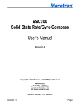
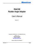
Installation Instructions
M4ARP-2R-E8 Fuel Flow Sensor
WARNING
NEVER disassemble the fuel flow sensor, except to remove the pulser cap, if necessary, in order to electrically connect the sensor to
the FFM100. The sensor is factory sealed, and disassembly will void the product warranty. If you feel that the sensor is not functioning
correctly, please contact Maretron Technical Support.
Operating Principle
When fluid passes through the sensor, the rotors turn, as shown in the figure on the right. Magnets which are located in
the rotors will pass across sensors in the sensor circuit board. Pulses from these sensors are transmitted to the FFM100
which performs flow rate calculations based on the received pulses.
Instructions
Please follow these instructions to connect the M4ARP-2R-E8 fuel flow sensor to the NMEA 2000® network via a Maretron FFM100 Fuel Flow Monitor.
1.
The fuel flow sensors are compatible with fuel, lubricating oil, hydraulic fluid, or other clean petroleum based products and should not be used with any other fluid types.
2.
The fuel flow sensor contains shafts on which the oval rotors spin. The fuel flow sensor must be mounted so that these rotor shafts are always in a horizontal plane
(parallel with the ground or water surface). The rotor shafts are parallel to the screws attaching the sensor cap to the sensor base, so ensure that these screws are in a
horizontal plane. Please refer to Figure 1 below for examples of correct and incorrect orientations.
9
U
9
Figure 1 - Correct and Incorrect Mounting Orientations
3.
To prevent damage from dirt or foreign matter, it is required that either 1) a diesel fuel filter capable of filtering out 75 micron particles or 2) a Y or basket type 60 mesh
strainer be installed as close as possible to the inlet side of the sensor.
4.
Install so that the direction of the “FLOW” arrows on the sensor label matches the direction of fuel flow.
5.
The M4ARP-2R-E8 fuel flow sensor accessory for the FFM100 is fitted with 1/2” NPT female threads.
6.
Use a liquid thread sealant on all pipe threads. Do NOT use Teflon tape. The fittings should be tightened hand tight, then a further ½ to 1 turn. Do not over tighten.
7.
Extreme care must be taken when installing the sensor. Pipe strain or over tightening sensor connections can cause sensor damage.
8.
To prevent damage to the sensor from entrapped air during initial commissioning or after maintenance, slowly fill the system with fuel (this will prevent damage caused
by air purge). Failure to do this could damage the sensor. NEVER blow or send compressed air through the sensor as this may over rev and damage the sensor.
9.
The sensor is supplied with a 10’ cable which is pre-installed to the sensor using a waterproof cable gland. If you are using this cable, please skip forward to step 11. If
you are using your own cable, cable gland, or waterproof conduit, please go to step 10.
10.
(Optional – only if using your own cable, cable gland, or conduit) Remove the pulser cap by removing the pulser cap mounting screws, and install a waterproof cable
gland or waterproof conduit to the ½” female NPT fitting on the pulser cap. Please refer to Figure 4 on the reverse side for details. Route a six-conductor cable into the
sensor cap and connect the conductors to the terminal strip on the printed circuit board mounted underneath the pulser cap. Do NOT remove the printed circuit board
from the sensor. Replace the pulser cap (which can be replaced in any orientation) and secure with the pulser cap mounting screws.
11.
Connect the other end of the cable to the corresponding terminals on the appropriate free pressure monitoring channel on an FFM100. Please refer to Figure 2 below
for details (the wire colors in the figure are those of the supplied cable).
12.
Use a Maretron DSM250 display (firmware 1.4.12 or higher), Maretron N2KAnalyzer software, or other Maretron display product capable of configuring the FFM100 to
configure the connected channel. Please refer to the FFM100 User’s Manual for configuration details. Be sure to program the FFM100 with the K factor printed on the
fuel flow sensor.
13.
Supply Power to the NMEA 2000 network and verify that the flow channel indicates a valid flow rate and temperature reading.
Red
Black
Orange
Blue
Green
White
Fluid Flow
Sensor Pin
1
2
3
4
5
6
FFM100
Channel 0 Pin
1
2
3
4
5
6
FFM100
Channel 1 Pin
7
8
9
10
11
12
Red
Black
Orange
Blue
Green
White
1
6
FFM100 Screw Terminals
3
4
5
6
7
8
9 10 11 12
Fluid Flow Sensor Pins
A0
B0
C0
T0
P1
G1
A1
B1
C1
T1
2
P0
G0
1
FFM100 Channel 0 Pins
FFM100 Channel 1 Pins
Figure 2 – Fuel Flow Sensor Connection Diagram
Copyright © 2011 Maretron, LLP All Rights Reserved
P/N: M003023 Rev.1.0 12/11
Figure 3 - Fuel Flow Sensor Mechanical Drawing
Fuel Flow Sensor Specifications
Flow Range
Nominal K Factor
180 LPH to 1500 LPH
112 pulses/L (424 pulses/Gal)
(48 GPH to 396 GPH)
Specification
Operating
Temperature
Construction
Port Size
Accuracy %
Reading
Maximum
Viscosity
Maximum
Operating
Pressure
Strainer Size
Weight
Dimensions
Pulser Cap
Mounting Screws
Pulser Cap
Value
-10°C to 80°C (14°F to 186°F)
Meter Body and Cap: Aluminum 601-T6
O-Ring:
Viton
Magnet Housings:
Stainless steel 316L
Shafts:
Stainless Steel 316L
Rotors:
PPS Ryton BR42B Grade
½” NPT Female
± 0.25% (With K factor on sensor entered into FFM100)
Sensor Body
1000 cPs
55 Bar (800 PSI)
60 Mesh (If not already installed after fuel filter)
907g (32.0 oz)
100 x 96 x 105 mm (3.94 x 3.78 x 4.13 in.)
Figure 4 – Pulser Cap Removal
For installation support, please contact:
Maretron, LLP
9014 N. 23rd Ave #10
Phoenix, AZ 85021-7850
Telephone: (+1) 866-550-9100
E-mail: [email protected]
Web: http://www.maretron.com
Copyright © 2011 Maretron, LLP All Rights Reserved
P/N: M003023 Rev.1.0 12/11