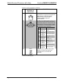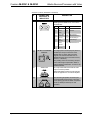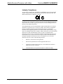
1
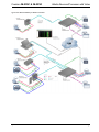
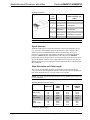
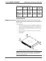
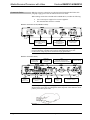
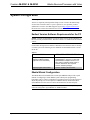
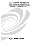
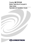
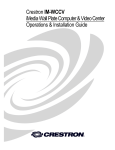
Crestron IM-RXV1 & IM-RXV3 iMedia Receiver/Processor with Video Operations & Installation Guide This document was prepared and written by the Technical Documentation department at: Crestron Electronics, Inc. 15 Volvo Drive Rockleigh, NJ 07647 1-888-CRESTRON All brand names, product names and trademarks are the property of their respective owners. ©2006 Crestron Electronics, Inc. Crestron IM-RXV1 & IM-RXV3 iMedia Receiver/Processor with Video Contents iMedia Receiver/Processor with Video: IM-RXV1 & IM-RXV3 1 Introduction ............................................................................................................................... 1 Features and Functions ................................................................................................ 1 Applications................................................................................................................. 2 Specifications .............................................................................................................. 4 Physical Description.................................................................................................... 5 Industry Compliance ................................................................................................. 10 Setup ........................................................................................................................................ 11 Network Wiring......................................................................................................... 11 IM Wiring.................................................................................................................. 11 Hardware Hookup ..................................................................................................... 13 System Configuration .............................................................................................................. 15 Earliest Version Software Requirements for the PC ................................................. 15 iMedia Wizard Configuration.................................................................................... 15 Uploading and Upgrading........................................................................................................ 16 Establishing Communication..................................................................................... 16 Firmware ................................................................................................................... 17 Problem Solving ...................................................................................................................... 18 Troubleshooting......................................................................................................... 18 Reference Documents................................................................................................ 18 Further Inquiries ........................................................................................................ 18 Future Updates .......................................................................................................... 19 Return and Warranty Policies .................................................................................................. 20 Merchandise Returns / Repair Service ...................................................................... 20 CRESTRON Limited Warranty................................................................................. 20 Operations & Installation Guide – DOC. 6478 Contents • i Crestron IM-RXV1 & IM-RXV3 iMedia Receiver/Processor with Video iMedia Receiver/Processor with Video: IM-RXV1 & IM-RXV3 Introduction Features and Functions • • • • • • • • • Simple, affordable solution for single-display multimedia presentation Models with one (IM-RXV1) or three (IM-RXV3) IM transmitter inputs available iMedia transport for fast and easy single-cable installation using CresCAT™-IM cable Supports XGA resolution up to 84 feet, and UXGA up to 34 feet over CresCAT-IM cable Receives and displays composite video signals Built-in LAN, RS-232, IR, relays and digital input control ports Built-in 20 Watt stereo amplifier and line-level outputs Complete setup in minutes using iMedia Wizard Software Built-in Web-server supports e-Control®2 and RoomView® The iMedia Transport The iMedia transport utilizes a single CAT5e* type cable to transmit computer RGB, video, and stereo audio signals to a single projector or plasma display. A typical XGA signal (1024 X 768 pixels at 60Hz) can be transmitted up to 84 feet using iMedia, while higher resolutions up to 1600 x 1200 can be handled over shorter distances. Composite video signals can be transmitted up to 218 feet. Audio is transmitted digitally at 20-bit, 48 kHz resolution. Control and power signals are also contained on the same wire, eliminating the need for separate control or power cables. * For iMedia use CresCAT-IM cable, or quality CAT5e/CAT6 cable having a maximum delay skew of 15ns per 100m. iMedia Receiver Mounted at the projector or plasma display, the IM-RXV1 and IM-RXV3 receive the iMedia (IM) signal from up to three IM transmitters, breaking out the RGB, video, Operations & Installation Guide – DOC. 6478 iMedia Receiver/Processor with Video: IM-RXV1 & IM-RXV3 • 1 iMedia Receiver/Processor with Video Crestron IM-RXV1 & IM-RXV3 audio, and control signals for connection to the display device. Adjustable bandwidth compensation is provided to maximize image quality over long cable runs. Integrated Audio The IM-RXV1 and IM-RXV3 include a built-in 20 watt stereo amplifier to drive a pair of 8 ohm speakers. Balanced line-level outputs are also provided to allow the audio signal to be connected directly to inputs on the display device or fed to a pair of powered speakers. Onboard digital signal processing affords adjustment of master volume, bass, treble and balance settings at setup. Display Control The IM-RXV1 and IM-RXV3 contain both IR and bidirectional RS-232 ports to enable full control of the display device. Two relay ports are also included for control of a projection screen or lift. In addition, the four digital input ports can accept the direct connection of room occupancy sensors and power sensors for enhanced automation and monitoring. e-Control®2 and RoomView® Despite its simple design and low cost, the IM-RXV1 and IM-RXV3 support Crestron's powerful e-Control 2 XPanel and RoomView applications, delivering the industry's best help desk and resource management solution for any number of rooms equipped with iMedia. Fast, Easy Setup System setup takes mere minutes using iMedia Wizard software, providing easy start-to-finish configuration, adjustment, and documentation. Applications The IM-RXV1 and IM-RXV3 are part of the Crestron® iMedia line of network devices, room control systems and signal routing solutions. The line of iMedia devices includes receivers and transmitters. Consult the Crestron website for a complete and current listing of the iMedia product line. NOTE: The composite video output of the IM-RXV1 and IM-RXV3 are not enabled when using the iMedia transmitters without composite video inputs. The IM-RXV1 and IM-RXV3 can be placed on a table or mounted to a surface using the included brackets. These receivers can also be mounted to a pipe using the optional pole mount kit MK-IM-RX. NOTE: The IM-RXV1 and IM-RXV3 are not Cresnet® devices. The IM-RXV1 and IM-RXV3 are part of a family of compatible iMedia devices, all capable of working together to put on simple to complex media presentations. The following diagram shows the interconnections. 2 • iMedia Receiver/Processor with Video: IM-RXV1 & IM-RXV3 Operations & Installation Guide – DOC. 6478 Crestron IM-RXV1 & IM-RXV3 iMedia Receiver/Processor with Video Typical Two-Room Installation for Media Presentation Operations & Installation Guide – DOC. 6478 iMedia Receiver/Processor with Video: IM-RXV1 & IM-RXV3 • 3 iMedia Receiver/Processor with Video Crestron IM-RXV1 & IM-RXV3 Specifications Specifications for the IM-RXV1 & IM-RXV3 are listed in the following table. IM-RXV1 & IM-RXV3 Specifications SPECIFICATION DETAILS Outputs RGB Gain 0 dB (75 ohm termination) Resolution 1024 x 768 @ 60Hz with maximum cable length of 84 feet, 1600 x 1200 @ 60Hz with maximum cable length of 34 feet; refer to “Video Resolution and Cable Length” on page 12 for other resolutions Video Gain 0 dB (75 ohm termination) Formats 480i (NTSC), 576i (PAL) Audio (Line-Level) Output Level 4 VRMS balanced, 2 VRMS unbalanced Output Impedance 200 ohms balanced, 100 ohms unbalanced Frequency Response 20 Hz to 20 kHz ±0.5 dB Signal-to-Noise Ratio 82 dB, 20 Hz to 20 kHz, A-weighted Total Harmonic Distortion + Noise 0.05%, 20 Hz to 20 kHz Speaker Output Power 10 Watts Per Channel (x2) into 8 ohms (minimum impedance) Frequency Response 20 Hz to 20 kHz ±1 dB Signal-to-Noise Ratio 80 dB, 20 Hz to 20 kHz, A-weighted Total Harmonic Distortion + Noise 0.7%, 20 Hz to 20 kHz Infrared/Serial IR output Relay Rating (1) mini-phone jack, IR/Serial port; Up to 1.2 MHz (2) Normally open, isolated relays; 2A, 50V AC/DC; MOV arc suppression across contacts Inputs IM IM-RXV1: (1) IM port connects to IM output of IM transmitter devices IM-RXV3: (3) IM ports connect to IM output of IM transmitter devices Digital (4) digital inputs; Rated for 0-24V DC, referenced to GND; Input Impedance 2k ohms pulled up to 5V DC Logic Threshold 2.5V DC nominal (Continued on following page) 4 • iMedia Receiver/Processor with Video: IM-RXV1 & IM-RXV3 Operations & Installation Guide – DOC. 6478 Crestron IM-RXV1 & IM-RXV3 iMedia Receiver/Processor with Video IM-RXV1 & IM-RXV3 Specifications (Continued) SPECIFICATION DETAILS Communications Serial (1) DB9, male, bidirectional RS-232 port; Up to 115.2k baud, hardware and software handshaking support for communication with serial devices Console (1) RJ-11 female, bidirectional RS-232 computer console port for connection to PC Ethernet (1) RJ-45 port for Ethernet communications Audio A-D Conversion 20-bit, 48 kHz Bass/Treble Gain Range ±12 dB 10/100 BaseT, static IP or DHCP/DNS, auto-negotiating, built-in Web server, supports Crestron e-Control 2, XPanel, and RoomView applications Ethernet Power Requirements External Power Supply (Included) Input: 100-240 VAC @ 50-60 Hz Output: 54 Watts (3 Amps) @ 18 Volts DC Environmental Temperature 41° to 104°F (5° to 40°C) Humidity 10% to 90% RH (non-condensing) Black metal; freestanding, surface mount using "L" brackets provided, or pole mount using optional pole mount kit (sold separately) Enclosure Dimensions (without brackets) Height 1.61 in (4.08 cm) Width 8.75 in (22.23 cm) Depth 7.69 in (19.53 cm) Weight 1.75 lbs (0.80 kg) Available Accessories MK-IM-RX Pole mount kit CNSP-XX Custom serial interface cable STIRP IR probe CNXRMCS Current Sensor Physical Description This section provides information on the connections, controls, and indicators available on your IM-RXV1 and IM-RXV3. IM-RXV1 Physical Views (Front (L) and Rear (R)) Operations & Installation Guide – DOC. 6478 iMedia Receiver/Processor with Video: IM-RXV1 & IM-RXV3 • 5 iMedia Receiver/Processor with Video Crestron IM-RXV1 & IM-RXV3 IM-RXV3 Physical Views (Front (L) and Rear (R)) IM-RXV1 & IM-RXV3 Overall Dimensions 7.31 in (18.57 cm) 7.69 in (19.53 cm) 8.60 in (21.84 cm) 8.75 in (22.23 cm) 1 2 3 4 5 6 7 8 9 10 11 12 13 1.30 in 1.61 in (3.31 cm) (4.08 cm) 14 15 16 IM-RXV1 14 15 16 IM-RXV3 6 • iMedia Receiver/Processor with Video: IM-RXV1 & IM-RXV3 Operations & Installation Guide – DOC. 6478 Crestron IM-RXV1 & IM-RXV3 iMedia Receiver/Processor with Video Connectors, Controls, & Indicators # CONNECTORS, CONTROLS, & INDICATORS 1 POWER INPUT 2 PWR LED 3 SOFTWARE RESET Recessed below the front panel. Press this button while the system is running to restart the program. 4 RELAY OUTPUT (2) Normally open isolated relays; rated to 2A, 50V (AC/DC) with MOV arc suppression across contacts for control of “real world” loads. A nine-pin terminal block interface connector is included. 5 INPUT (4) Digital inputs. Connect to 24 VDC (max) logic output or contact closure from external devices. A five-pin terminal block interface connector is included. 6 INPUT LED Indicates when an input signal is received on any of the four digital inputs. 7 IR LED Indicates when an output signal is transmitted from the IR OUT port. 8 IR OUT (1) 3.5mm tip-ring-sleeve (TRS) mini-phone port enables infrared communications to other devices; Use Crestron Infrared Emitter Probe (part number STIRP, sold separately) for controlling infrared devices. DESCRIPTION Power connector require 3.0 A @ 18 VDC from included power supply. Indicates power from the included power supply. Tip: IR Data Out Ring: No Connection Sleeve: Ground Tip Ring Sleeve 9 COMPUTER One 6-pin RJ-11 female, computer console port. Use with STCP-502 serial cable (not included). PIN FUNCTION PIN FUNCTION 1 CTS 4 TXD 2 GND 5 RTS 3 RXD 6 No Connect (Continued on following page) Operations & Installation Guide – DOC. 6478 iMedia Receiver/Processor with Video: IM-RXV1 & IM-RXV3 • 7 iMedia Receiver/Processor with Video Crestron IM-RXV1 & IM-RXV3 Connectors, Controls, & Indicators (Continued) # CONNECTORS, CONTROLS, & INDICATORS DESCRIPTION 10 LAN One 8-wire, RJ-45 female connector with two LED indicators. The green LED indicates link status while the yellow LED indicates Ethernet activity. The port supports 10BaseT/100BaseTX Ethernet communications. 11 COM (2) DB9, male, bidirectional RS-232 ports; Up to 115.2k baud with hardware and software handshaking support for communication with serial devices. Can also be used for modem communications. The following table lists the pin assignments of the serial ports. 12 VIDEO PIN DIRECTION DESCRIPTION 1 To IM-RXV1/3 (DCD) Data Carrier Detect 2 To IM-RXV1/3 (RXD) Receive Data 3 From IM-RXV1/3 (TXD) Transmit Data 4 From IM-RXV1/3 (DTR) Data Terminal Ready 5 Common (GND) Ground 6 From IM-RXV1/3 (DSR) Data Set Ready 7 From IM-RXV1/3 (RTS) Request To Send 8 To IM-RXV1/3 (CTS) Clear To Send 9 To IM-RXV1/3 (RI) Ring Indicator (1) RCA, female, composite video output. Displays composite video signal from composite source connected to IM transmitter. (Continued on following page) 8 • iMedia Receiver/Processor with Video: IM-RXV1 & IM-RXV3 Operations & Installation Guide – DOC. 6478 Crestron IM-RXV1 & IM-RXV3 iMedia Receiver/Processor with Video Connectors, Controls, & Indicators (Continued) # CONNECTORS, CONTROLS, & INDICATORS DESCRIPTION 13 RGBHV (1) DB15HD, female, RGB output. Displays RGB signal from RGB source connected to IM transmitter. 14 IM INPUT & PEAKING CONTROL PIN FUNCTION PIN FUNCTION 1 Red Video 9 No Connect 2 Green Video 10 Ground 3 Blue Video 11 No Connect 4 Reserved 12 Monitor Sense 1 5 Ground 13 Horizontal Sync 6 Red Ground 14 Vertical Sync 7 Green Ground 15 Monitor Sense 2 8 Blue Ground This eight-pin RJ-45 transport port (three on IM-RXV3) is the input connection of the iMedia cable. It carries audio and video signals over CresCAT-IM cable from an iMedia transmitter (such as the IM-FTCC-B, IM-TCC, or IM-WCC). The peaking control is used during setup for video cable length compensation. Refer to “iMedia Wizard Configuration” on page 15 for additional details. 15 AUDIO OUT This 5-pin detachable terminal block audio output connector provides balanced/unbalanced line-level left and right audio for application to an external amplifier. 16 SPEAKER OUT The left and right speaker connectors (two 2-pin detachable terminal block connectors, 5 mm spacing) provide 20 Watts of amplified audio (10 Watts per channel) into 8 Ω speakers. Operations & Installation Guide – DOC. 6478 iMedia Receiver/Processor with Video: IM-RXV1 & IM-RXV3 • 9 iMedia Receiver/Processor with Video Crestron IM-RXV1 & IM-RXV3 Industry Compliance As of the date of manufacture, the IM-RXV1 and IM-RXV3 have been tested and found to comply with specifications for CE marking and standards per EMC and Radiocommunications Compliance Labelling. NOTE: These devices comply with part 15 of the FCC rules. Operation is subject to the following two conditions: (1) these devices may not cause harmful interference, and (2) these devices must accept any interference received, including interference that may cause undesired operation. This equipment has been tested and found to comply with the limits for a Class B digital device, pursuant to part 15 of the FCC Rules. These limits are designed to provide reasonable protection against harmful interference in a residential installation. This equipment generates, uses and can radiate radio frequency energy and, if not installed and used in accordance with the instructions, may cause harmful interference to radio communications. However, there is no guarantee that interference will not occur in a particular installation. If this equipment does cause harmful interference to radio or television reception, which can be determined by turning the equipment off and on, the user is encouraged to try to correct the interference by one or more of the following measures: Reorient or relocate the receiving antenna. Increase the separation between the equipment and receiver. Connect the equipment into an outlet on a circuit different from that to which the receiver is connected. Consult the dealer or an experienced radio/TV technician for help. 10 • iMedia Receiver/Processor with Video: IM-RXV1 & IM-RXV3 Operations & Installation Guide – DOC. 6478 Crestron IM-RXV1 & IM-RXV3 iMedia Receiver/Processor with Video Setup Network Wiring When wiring an iMedia system, consider the following: • Use Crestron Certified Wire. • Use Crestron power supplies for Crestron equipment. IM Wiring Using a proprietary signal routing solution, RGBHV, composite video, audio, power and control signals are all transported using a single cable solution called iMedia. The iMedia transport system port is capable of managing computer RGB, composite video, and audio signals simultaneously through one CresCAT-IM cable, simplifying installations. Routing CresCAT-IM cable (low-skew CAT5e) is less expensive and a much simpler solution for the wiring of iMedia systems than routing multi-colored, multiconductor coax cable. All Crestron products using the iMedia transport system are capable of sending and receiving iMedia signals via CresCAT-IM cable. Installation of any iMedia device is as simple as installing one iMedia cable from output to input. Installations are affordable, and fast. Quantity and Packaging • CRESCAT-IM-P-B500 is a low-skew CAT5e cable, plenum-rated, available in a 500 foot box • CRESCAT-IM-P-SP500is a low-skew CAT5e cable, plenum-rated, available in a 500 foot spool • CRESCAT-IM-P-SP1000 is a low-skew CAT5e cable, plenum-rated, available is a 1000 foot spool For more information on CresCAT and other wire products, visit the Crestron website (www.crestron.com/features/wire). Pin Assignments The pin assignment is based on the EIA/TIA 568B RJ-45 Jack standard. Power is supplied to the IM transmitters via the audio circuit. To determine which pin is number 1, hold the cable so that the end of the eight pin modular jack is facing you, with clip down and copper side up. When looking down at the copper connections, pin 1 is on the far right. Operations & Installation Guide – DOC. 6478 iMedia Receiver/Processor with Video: IM-RXV1 & IM-RXV3 • 11 iMedia Receiver/Processor with Video Crestron IM-RXV1 & IM-RXV3 iMedia Pin Assignment RJ-45 Male Connector RJ-45 Pin Number Wire Colors iMedia Assignment RGB, Composite and Audio 1 White/Orange - RGB Red 2 Orange + RGB Red 3 White/Green - RGB Green 4 Blue + Audio/Power 5 White/Blue - Audio/Power 6 Green + RGB Green 7 White/Brown - RGB Blue / Composite 8 Brown + RGB Blue / Composite NOTE: Power is supplied to pins 4 and 5 from the IM receivers. Signal Selection The RGB signal connected to the IM transmitter is delivered to the display device (e.g., projector) via the RGBHV output of an IM receiver. The composite video signal connected to the IM transmitter is delivered to the display device (e.g., projector) via the composite video output of an IM receiver. Each IM transmitter possesses a SELECT button (IM transmitters with video have two SELECT buttons) that activates an input. The receiver automatically routes the last activated input to the RGB or composite video output and deactivates any prior selection. In addition, the display's power and input selection commands can be controlled via the IR or COM port. Video Resolution and Cable Length The receiver can accomplish frequency compensation on each input to achieve correct operation. This compensation scheme is effective for CresCAT-IM cables as long as the maximum skew of 15 ns per 100 m is not exceeded. NOTE: For proper operations and performance of every iMedia system, always use CresCAT-IM cable. Maximum Resolution and Cable Length RESOLUTION REFRESH RATE (HZ) PIXEL RATE (MHZ) PIXEL TIME (NS) MAX LENGTH (FEET) VGA (640 X 480) 60 72 85 25.18 31.50 36.00 39.7 31.7 27.8 218.5 174.6 152.8 SVGA (800 X 600) 56 72 85 36.00 50.00 56.25 27.8 20.0 17.8 152.8 110.0 97.8 XGA (1024 X 768) 60 70 85 65.00 75.00 94.50 15.4 13.3 10.6 84.6 73.3 58.2 (Continued on following page) 12 • iMedia Receiver/Processor with Video: IM-RXV1 & IM-RXV3 Operations & Installation Guide – DOC. 6478 Crestron IM-RXV1 & IM-RXV3 iMedia Receiver/Processor with Video Maximum Resolution and Cable Length (Continued) RESOLUTION REFRESH RATE (HZ) PIXEL RATE (MHZ) PIXEL TIME (NS) MAX LENGTH (FEET) SXGA (1280 X 1024) 60 75 85 108.00 135.00 157.50 9.3 7.4 6.3 50.9 40.7 34.9 UXGA (1600 X 1200) 60 70 85 162.00 189.00 229.50 6.2 5.3 4.4 34.0 29.1 24.0 COMPOSITE VIDEO 218.5 Hardware Hookup Mounting The IM-RXV1 & IM-RXV3 can be mounted to any surface using the included mounting brackets. These brackets must be installed prior to mounting. Complete the following procedure to attach the brackets to the unit. The only tool required is a #1 Phillips screwdriver. To install the brackets: 1. There are screws that secure each side of the IM-RXV1 & IM-RXV3 top cover. Using a #1 Phillips screwdriver, remove the screws at each corner of the top cover. Refer to the diagram following step 3 for a detailed view. 2. Position a bracket so that its mounting hole aligns with the hole vacated by the screws in step 1. 3. Secure the bracket to the unit with a screw from step 1, as shown in the following diagram. Ear Attachment 4. Repeat procedure (steps 1 through 3) for each remaining bracket. NOTE: The MK-IM-RX mounting kit is also available for mounting the IM-RXV1 or IM-RXV3 to a pipe. Details can be found in the latest version of MK-IM-RX Installation Guide (Doc. 6451) which is available from the Crestron website (http://www.crestron.com/manuals). Operations & Installation Guide – DOC. 6478 iMedia Receiver/Processor with Video: IM-RXV1 & IM-RXV3 • 13 iMedia Receiver/Processor with Video Connect the Device Crestron IM-RXV1 & IM-RXV3 Make the necessary connections as called out in the illustrations that follows this paragraph. Apply power after all connections have been made. When making connections to the IM-RXV1 and IM-RXV3, consider the following: • Use Crestron power supplies for Crestron equipment. • The included cable cannot be extended. Hardware Connections (Front, IM-RXV3 shown) IM INPUT: iMEDIA PORT RECEIVES AUDIO, VIDEO, AND RGB SIGNALS AUDIO: BALANCED OR UNBALANCED OUTPUT TO AMPLIFIER SPEAKER: AMPLIFIED STEREO AUDIO OUTPUT NOTE: For optimum performance, Crestron strongly recommends using CresCAT-IM cable, available from Crestron. Other high-quality/low skew CAT5e/CAT6 wiring may also be used with varying performance. Hardware Connections (Rear) DIGITAL INPUTS: FOUR SCHMIDT TRIGGER TYPE POWER: FROM POWER SUPPLY (18 VDC, 3.0 A) RELAY OUTPUT: TWO LOW VOLTAGE CONTACT CLOSURE RELAYS COMPUTER: RJ-11 SERIAL PORT TO LOAD FILES OR CONSOLE IR OUTPUT: TO STIRP COM: BI-DIRECTIONAL RS-232 WITH HARDWARE AND SOFTWARE HANDSHAKING AND MODEM CONTROL LAN: 10/100 BASE-T ETHERNET TO LAN RGB OUTPUT: TO DISPLAY DEVICE COMPOSITE VIDEO OUTPUT: TO DISPLAY DEVICE NOTE: the power supply cable is equipped with a snap lock connector. Always disconnect the power cable by pulling back on the snap lock of the connector. Never pull the power cable by the cord. 14 • iMedia Receiver/Processor with Video: IM-RXV1 & IM-RXV3 Operations & Installation Guide – DOC. 6478 Crestron IM-RXV1 & IM-RXV3 iMedia Receiver/Processor with Video System Configuration Have a question or comment about Crestron software? Answers to frequently asked questions (FAQs) can be viewed in the Online Help section of the Crestron website. To post a question or view questions you have submitted to Crestron’s True Blue Support, log in at http://support.crestron.com. First-time users will need to establish a user account. Earliest Version Software Requirements for the PC NOTE: Crestron recommends that you use the latest software to take advantage of the most recently released features. The latest software is available from the Crestron website. Crestron has developed an assortment of Windows-based software tools to develop a Cresnet system. The following are the minimum recommended software versions for the PC: Software TASK REQUIRED SOFTWARE VERSION Simplified configuration with wizards for iMedia systems (optional but recommended). iMedia Wizard; part of Crestron SystemBuilder™ version 3.0 or later with SystemBuilder Templates version 3.0 or later; Refer to software release notes or Crestron website for other required Crestron software packages. Upload program and firmware. Crestron Toolbox 1.02.18 or later. iMedia Wizard Configuration The iMedia Wizard is included with Crestron SystemBuilder and provides a quick method of configuring a custom iMedia system without prior programming knowledge. Once a system is configured, a test pattern can be sent to the projector to adjust the peaking level of each input. For additional details, download Crestron SystemBuilder from the Crestron website and examine the extensive help file. NOTE: All configuration is completed within the iMedia wizard only. This system cannot be configured in SystemBuilder or SIMPL Windows. Operations & Installation Guide – DOC. 6478 iMedia Receiver/Processor with Video: IM-RXV1 & IM-RXV3 • 15 iMedia Receiver/Processor with Video Crestron IM-RXV1 & IM-RXV3 Uploading and Upgrading Crestron recommends using the latest programming software and that each device contains the latest firmware to take advantage of the most recently released features. However, before attempting to upload or upgrade, it is necessary to establish communication. Establishing Communication Use Crestron Toolbox for communicating with the IM-RXV1 and IM-RXV3; refer to the Crestron Toolbox help file for details. There are two methods of communication. Direct Serial Communication NOTE: Required for initial setup of Ethernet parameters. Direct Serial Communication PC RUNNING CRESTRON TOOLBOX SERIAL VIA CRESTRON CABLE STCP-502 OR EQUIVALENT IM-RXV1 / IM-RXV3 • The COMPUTER port on the IM-RXV1 and IM-RXV3 connects to the serial port on the PC via a serial cable (Crestron STCP-502 or equivalent). • Use the Address Book in Crestron Toolbox to create an entry using the expected serial communication protocol (RS232, auto-detect baud rate, no parity, 8 data bits, 1 stop bit, XON/XOFF disabled, RTS/CTS enabled). • Display the IM-RXV1 or IM-RXV3’s “System Info” window (click the icon); communications are confirmed when the device information is displayed. TCP/IP Communication Ethernet Communication PC RUNNING CRESTRON TOOLBOX ETHERNET IM-RXV1 / IM-RXV3 • Establish direct serial communication between IM-RXV1/IM-RXV3 and PC. • Enter the IP address, IP mask, and default router of the IM-RXV1/ IM-RXV3 via the Crestron Toolbox (Functions | Ethernet Addressing); otherwise enable DHCP. • Confirm Ethernet connections between IM-RXV1/IM-RXV3 and PC. If connecting through a hub or router, use CAT5 straight through cables with 8-pin RJ-45 connectors. Alternatively, Use a CAT5 crossover cable to connect the two LAN ports directly, without using a hub or router. • Use the Address Book in the Crestron Toolbox to create an entry for the IM-RXV1/IM-RXV3 with the IM-RXV1/IM-RXV3’s TCP/IP communication parameters. 16 • iMedia Receiver/Processor with Video: IM-RXV1 & IM-RXV3 Operations & Installation Guide – DOC. 6478 Crestron IM-RXV1 & IM-RXV3 • iMedia Receiver/Processor with Video Display the “System Info” window (click the IM-RXV1/IM-RXV3 entry. icon) and select the Firmware Upgrade the IM-RXV1 and IM-RXV3 firmware via Crestron Toolbox. • Establish communications with the IM-RXV1 or IM-RXV3 and display the “System Info” window. • Select Functions | Firmware… to upgrade the firmware. For details on upgrading firmware, refer to the Crestron Toolbox help file. Operations & Installation Guide – DOC. 6478 iMedia Receiver/Processor with Video: IM-RXV1 & IM-RXV3 • 17 iMedia Receiver/Processor with Video Crestron IM-RXV1 & IM-RXV3 Problem Solving Troubleshooting The following table provides corrective action for possible trouble situations. If further assistance is required, please contact a Crestron customer service representative. IM-RXV1 and IM-RXV3 Troubleshooting TROUBLE POSSIBLE CAUSE(S) PWR LED does not illuminate. No video output displayed. CORRECTIVE ACTION Not receiving power. Verify that the power supply cable and power supply connection to the AC are properly attached. Incorrect power supply. Only use a Crestron power supply. Incorrect cable connection. Verify display device connection. Verify iMedia output cable connection is secure. Video from source is garbled or no output. Wrong input selected on transmitter. Select correct input on transmitter. Incorrect cable connections. Verify iMedia cable connections. Verify maximum iMedia cable length. Not controlling the display device. Peak adjustment incorrect. Readjust peak control. Incorrect wiring. Check wiring and connectors between the IM-RXV1/3 and the display device. Reference Documents The latest version of all documents mentioned within the guide can be obtained from the Crestron website (http://www.crestron.com/manuals). This link will provide a list of product manuals arranged in alphabetical order by model number. List of Related Reference Documents DOCUMENT TITLE CNXRMCS Current Sensor for Room Solution Boxes MK-IM-RX Pole Mount Kit for iMedia Receivers STIRP Infrared Emitter Further Inquiries If you cannot locate specific information or have questions after reviewing this guide, please take advantage of Crestron's award winning customer service team by calling the Crestron corporate headquarters at 1-888-CRESTRON [1-888-273-7876]. 18 • iMedia Receiver/Processor with Video: IM-RXV1 & IM-RXV3 Operations & Installation Guide – DOC. 6478 Crestron IM-RXV1 & IM-RXV3 iMedia Receiver/Processor with Video For assistance in your local time zone, refer to the Crestron website (http://www.crestron.com/) for a listing of Crestron worldwide offices. You can also log onto the online help section of the Crestron website to ask questions about Crestron products. First-time users will need to establish a user account to fully benefit from all available features. Future Updates As Crestron improves functions, adds new features, and extends the capabilities of the IM-RXV1 and IM-RXV3, additional information may be made available as manual updates. These updates are solely electronic and serve as intermediary supplements prior to the release of a complete technical documentation revision. Check the Crestron website periodically for manual update availability and its relevance. Updates are identified as an “Addendum” in the Download column. Operations & Installation Guide – DOC. 6478 iMedia Receiver/Processor with Video: IM-RXV1 & IM-RXV3 • 19 iMedia Receiver/Processor with Video Crestron IM-RXV1 & IM-RXV3 Return and Warranty Policies Merchandise Returns / Repair Service 1. No merchandise may be returned for credit, exchange, or service without prior authorization from CRESTRON. To obtain warranty service for CRESTRON products, contact an authorized CRESTRON dealer. Only authorized CRESTRON dealers may contact the factory and request an RMA (Return Merchandise Authorization) number. Enclose a note specifying the nature of the problem, name and phone number of contact person, RMA number, and return address. 2. Products may be returned for credit, exchange, or service with a CRESTRON Return Merchandise Authorization (RMA) number. Authorized returns must be shipped freight prepaid to CRESTRON, 6 Volvo Drive, Rockleigh, N.J. or its authorized subsidiaries, with RMA number clearly marked on the outside of all cartons. Shipments arriving freight collect or without an RMA number shall be subject to refusal. CRESTRON reserves the right in its sole and absolute discretion to charge a 15% restocking fee, plus shipping costs, on any products returned with an RMA. 3. Return freight charges following repair of items under warranty shall be paid by CRESTRON, shipping by standard ground carrier. In the event repairs are found to be non-warranty, return freight costs shall be paid by the purchaser. CRESTRON Limited Warranty CRESTRON ELECTRONICS, Inc. warrants its products to be free from manufacturing defects in materials and workmanship under normal use for a period of three (3) years from the date of purchase from CRESTRON, with the following exceptions: disk drives and any other moving or rotating mechanical parts, pan/tilt heads and power supplies are covered for a period of one (1) year; touchscreen display and overlay components are covered for 90 days; batteries and incandescent lamps are not covered. This warranty extends to products purchased directly from CRESTRON or an authorized CRESTRON dealer. Purchasers should inquire of the dealer regarding the nature and extent of the dealer's warranty, if any. CRESTRON shall not be liable to honor the terms of this warranty if the product has been used in any application other than that for which it was intended, or if it has been subjected to misuse, accidental damage, modification, or improper installation procedures. Furthermore, this warranty does not cover any product that has had the serial number altered, defaced, or removed. This warranty shall be the sole and exclusive remedy to the original purchaser. In no event shall CRESTRON be liable for incidental or consequential damages of any kind (property or economic damages inclusive) arising from the sale or use of this equipment. CRESTRON is not liable for any claim made by a third party or made by the purchaser for a third party. CRESTRON shall, at its option, repair or replace any product found defective, without charge for parts or labor. Repaired or replaced equipment and parts supplied under this warranty shall be covered only by the unexpired portion of the warranty. Except as expressly set forth in this warranty, CRESTRON makes no other warranties, expressed or implied, nor authorizes any other party to offer any warranty, including any implied warranties of merchantability or fitness for a particular purpose. Any implied warranties that may be imposed by law are limited to the terms of this limited warranty. This warranty statement supersedes all previous warranties. Trademark Information All brand names, product names, and trademarks are the sole property of their respective owners. Windows is a registered trademark of Microsoft Corporation. Windows95/98/Me/XP and WindowsNT/2000 are trademarks of Microsoft Corporation. 20 • iMedia Receiver/Processor with Video: IM-RXV1 & IM-RXV3 Operations & Installation Guide – DOC. 6478 Crestron IM-RXV1 & IM-RXV3 iMedia Receiver/Processor with Video This page intentionally left blank. Operations & Installation Guide – DOC. 6478 iMedia Receiver/Processor with Video: IM-RXV1 & IM-RXV3 • 21 iMedia Receiver/Processor with Video Crestron IM-RXV1 & IM-RXV3 This page intentionally left blank. 22 • iMedia Receiver/Processor with Video: IM-RXV1 & IM-RXV3 Operations & Installation Guide – DOC. 6478 Crestron IM-RXV1 & IM-RXV3 iMedia Receiver/Processor with Video This page intentionally left blank. Operations & Installation Guide – DOC. 6478 iMedia Receiver/Processor with Video: IM-RXV1 & IM-RXV3 • 23 Crestron Electronics, Inc. 15 Volvo Drive Rockleigh, NJ 07647 Tel: 888.CRESTRON Fax: 201.767.7576 www.crestron.com Operations & Installation Guide – DOC. 6478 (2014909) 05.06 Specifications subject to change without notice.