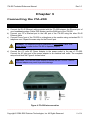
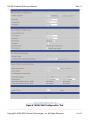
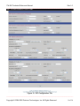
1
ITA-200 Technical Reference Manual
Rev 1.0
___________________________________________________________________
Intelligent Telephone Adapter Model ITA-200
Technical Reference Manual
Revision 1.0, October 26, 2006
_____________________________________________________________________________________
Copyright © 2004-2006 Quintum Technologies, Inc. All Rights Reserved
1 of 58
ITA-200 Technical Reference Manual
Rev 1.0
___________________________________________________________________
Contents
Chapter 1: Overview
Overview
General Specifications
Chapter 2: Getting to Know the ITA-200
The ITA-200’s Front Panel
The ITA-200’s Back Panel
Chapter 3: Connecting the ITA-200
Connect the ITA-200 Cables
Power-Up Sequence
Chapter 4: Configuring the ITA-200
1.
2.
3.
4.
5.
6.
Unit Information tab
WAN/LAN Configuration tab
SIP Configuration tab
Services tab
Misc. Servers tab
Maintenance tab
Chapter 5: Firmware Upgrade ITA200
1. Download firmware.
2. Auto Firmware update.
3. Special download.
Chapter 6: Voice prompts
1. List of command prompts.
2. Data input for voice prompts menu in ITA200.
Chapter 7: Download Config File
1. Download configuration file.
2. Auto config Download timer.
3. Download the configuration file through a voice prompt .
3
3
4
9
9
10
11
11
12
13
14
15
19
23
27
29
31
31
32
33
35
35
36
38
38
39
40
Appendix A. Dialing Plan
Appendix B. Update File
Appendix C. Config File
41
44
45
Disclaimer
58
_____________________________________________________________________________________
Copyright © 2004-2006 Quintum Technologies, Inc. All Rights Reserved
2 of 58
ITA-200 Technical Reference Manual
Rev 1.0
___________________________________________________________________
Chapter 1
Overview
Thanks and congratulations for purchasing the ITA-200, 2-Port Intelligent Telephone Adapter
with Integrated Router (ITA-200).
Quintum’s ITA-200 is an innovative and sophisticated access device that enables a user to take
advantage of Voice over Internet Protocol (VoIP) applications and services. In addition, it allows
the user to set up a home or small business network to share a single high-speed Internet
connection.
The WAN Port of the ITA-200 device connects to the Ethernet port of a Broadband Modem
(ADSL or Cable); the LAN Port of the ITA-200 adapter connects to the Ethernet port of the PC,
providing the PC with connectivity to the Internet. At the same time it provides the user with two
(2) additional telephone lines. The typical configuration diagram is shown below.
Figure 1: Typical Configuration.
The ITA-200 uses your broadband connection to deliver high quality voice communication and
features equivalent to, or exceeding, those of the Public Switched Telephone Network (PSTN).
It is compatible with any standard analog telephone set, and it is very easy to install and
configure. In addition to providing quality voice services, the ITA-200’s routing functionalities
allow the user to work in a safe environment protected from the external Internet.
The ITA-200 provides the user with instant connectivity to the Internet and gives the user the
capability of making free calls via the Internet any where in the world to other ITA-200 users.
_____________________________________________________________________________________
Copyright © 2004-2006 Quintum Technologies, Inc. All Rights Reserved
3 of 58
ITA-200 Technical Reference Manual
Rev 1.0
___________________________________________________________________
The ITA-200 is the ideal device to implement next generation telephone services using Voice
over Internet Protocol (VoIP) technology. It offers clear and compelling benefits for individual or
enterprise’s communications needs. The ITA-200 uses the most reliable and standard protocols
in the market today to ensure compatibility and reliability with existing VoIP networks. The ITA200 uses SIP (Session Initiation Protocol) for call signaling and control, T.38 for Fax over IP
networks, DHCP Client and Server for easy installation, HTTP Server for Web Management,
supports 2 compressed voice channels simultaneously (G.729A or G.723.1) for bandwidth
management, a sophisticated Quality of Service (QoS) for crystal clear communication, supports
enhanced features such us call waiting, call forwarding, 3-way calling, caller ID and many more
that make the ITA-200 the only solution for your VoIP network.
General Specifications
Interfaces
WAN
LAN
Phone 1
Phone 2
RJ-45 10/100 Base-T
RJ-45 10/100 Base-T
RJ-11 FXS
RJ-11 FXS
Power
+12 Volts DC, 1 A
Power Adapter: 100-240VAC, 50/60Hz, 1.8m Cord
Power Consumption: 6 Watts
LED’s
Power
Phone 1 status
Phone 2 status
WAN Speed
WAN Link/Activity
LAN Speed
LAN Link/Activity
Operating Temperature:
Storage Temperature:
Relative Humidity:
41 to 113˚F (5 to 45˚C)
-13 to 185˚F (-25 to 85˚C)
10 to 90%
Network Protocols
IPv4
- Internet Protocol Version 4
MAC Address (IEEE 802.3)
TCP
- Transmission Control Protocol
UDP
- User Datagram Protocol
ARP
- Address Resolution Protocol
_____________________________________________________________________________________
Copyright © 2004-2006 Quintum Technologies, Inc. All Rights Reserved
4 of 58
ITA-200 Technical Reference Manual
Rev 1.0
___________________________________________________________________
DNS
- Domain Name System
DCHP Client (WAN port)
- Dynamic Host Configuration Protocol
DCHP Server (LAN port)
- Dynamic Host Configuration Protocol
ICMP
- Internet Control Message Protocol
IGMP
- Internet Group Management Protocol
CIDR
- Classless Inter-Domain Routing
RTP
- Real-Time Transport Protocol
RIPv.1/v.2
- Routing Information Protocol
SLIP
- Serial Line Internet Protocol
CSLIP
- Compressed Serial Line Internet Protocol
PPP
- Point-to-Point Protocol
TFTP
- Trivial File Transfer Protocol
NFS
- Network File System
ONC
- Open Network Computing
RPC
- Remote Procedure Call
FTP
- File Transfer Protocol
RLOGIN
- Remote Login
RSH
- Remote Shell
Telnet
- The Internet Standard Protocol for Remote Login
SNTP
- Simple Network Transfer Protocol
NAT
- Network Address Translation
QoS
- Quality of Service (Data prioritization)
VPN
- Virtual Private Network
PPTP
- Point-to-Point Tunneling Protocol
IPSec
- Internet Protocol Secured
VoIP Interface Specifications
Two FXS Analog Telephone Ports,
Session Initiation Protocol Ver-2 (SIPv2),
SIP Proxy Redundancy,
NAT Traversal,
STUN,
Voice Codecs: G.711, G.723.1/A, G.726, G.729A/AB/E,
Adjustable Real-Time Audio Volume,
Adjustable Audio Frames per Packet,
FAX Relay (T.38, V.17, V.29, V27ter),
FAX Tone Detection and Pass-through,
Voice Band Data/Modem Tone Detection and Pass-through,
DTMF – In-Band/Out-of-Band (SIP Info),
Call Progress Tone Generation,
Adaptive Jitter Buffer, Full Duplex Audio,
Echo Cancellation (G.165/G.168),
Voice Activity Detection (VAD) with Silence Suppression,
Attenuation/Gain Adjustments,
Message Waiting Indicator (MWI) Tones and Visual,
_____________________________________________________________________________________
Copyright © 2004-2006 Quintum Technologies, Inc. All Rights Reserved
5 of 58
ITA-200 Technical Reference Manual
Rev 1.0
___________________________________________________________________
Reverse Polarity Control
Supported Enhanced Telephone Services
Call Waiting/Cancel Call Waiting
Caller ID with Name & Number
Call Waiting Caller ID with Name & Number
Caller ID Block
Call Forwarding: BNA, Busy and All Calls
Do Not Disturb (DND)
Call Transfer
Callback on Busy
Call Return
Call Rejection (general and selective)
Distinctive Ringing
Voice Mail/Message Waiting Warning Tone & Lamping
3-Way Conference Calling
Off-Hook Warning Tone
Speed Dialing
Hotline Dialing
Security
HTTP Web Configuration Password Protected
Administrator and End-User Passwords
Multiple End-Users Password
Telnet Password Protected
SIP Digest – Encrypted Authentication via MD5
Provisioning
Integrated Web Server for Configuration
Automatic Provisioning and Configuration via TFTP and HTTP
Syslog Support
Subscriber Line Interface Circuit (SLIC) Specifications
Ring Voltage
Ring Frequency
Ring Waveform
Maximum Ring Load
On-Hook Voltage (T/R)
Off-Hook Current
Terminating Impedance
60-90 Vrms Configurable
10 Hz – 40 Hz
Trapezoidal and Sinusoidal
3 REN
50 V
25 mA
Configurable North America 600 ohms, European CTR21
_____________________________________________________________________________________
Copyright © 2004-2006 Quintum Technologies, Inc. All Rights Reserved
6 of 58
ITA-200 Technical Reference Manual
Rev 1.0
___________________________________________________________________
Regulatory Compliance
FCC Part 15 Class B
VCCI
CE Mark
Front View
Back View
_____________________________________________________________________________________
Copyright © 2004-2006 Quintum Technologies, Inc. All Rights Reserved
7 of 58
ITA-200 Technical Reference Manual
Rev 1.0
___________________________________________________________________
Standing View
_____________________________________________________________________________________
Copyright © 2004-2006 Quintum Technologies, Inc. All Rights Reserved
8 of 58
ITA-200 Technical Reference Manual
Rev 1.0
___________________________________________________________________
Chapter 2
Getting to Know the ITA-200
The ITA-200’s Front Panel
LED’s on the ITA-200 front panel are shown in Figure 2.
Figure 2. ITA-200 Front Panel LED description.
Power
Green
ITA-200 is powered on.
Phone 1 &
Phone 2
Green
The telephone is off-hook.
Off
Blinking (Slow)
The telephone is on-hook and in service.
The telephone is not in service or not registered with a
SIP server.
The unit is downloading firmware from the TFTP or
HTTP server.
Blinking (Fast)
WAN Speed
WAN Link/
Activity
LAN Speed
LAN Link/
Activity
Off
Yellow
Blinking
10 Mbps connection.
100 Mbps connection.
There is data transmission in the WAN port.
Off
Yellow
Blinking
10 Mbps connection.
100 Mbps connection.
There is data transmission in the LAN port.
_____________________________________________________________________________________
Copyright © 2004-2006 Quintum Technologies, Inc. All Rights Reserved
9 of 58
ITA-200 Technical Reference Manual
Rev 1.0
___________________________________________________________________
The ITA-200’s Back Panel
The access to the interfaces is located in the back panel of the ITA-200. The ports are described
below in Figure 3.
Figure 3. ITA-200 Back Panel Interfaces
WAN RJ-45
This WAN (Wide Area Network) port connects to Ethernet
network devices, such as the ADSL/Cable modem, hub,
switch or router.
LAN RJ-45
This LAN (Local Area Network) port connects to the PC.
Phone 1 and Phone 2
RJ-11 telephone sockets that connect to the analog
telephone devices or facsimile machines.
Reset Button
The reset button can be use in two ways: reset the ITA-200 to
factory defaults by pressing the Reset button for more than
five (5) seconds; or restart the ITA-200 by pressing the Reset
button for less than two (2) seconds.
Power
Connects to the power adapter. The power requirement for
ITA-200 is +12VDC, 1 A.
Important: Factory reset to the ITA-200 will erase all of your settings (SIP
servers, phone numbers, WAN/LAN settings, etc.) and replace them with the
factory defaults. Do not perform a factory reset to the ITA-200 if you want to
retain these settings.
_____________________________________________________________________________________
Copyright © 2004-2006 Quintum Technologies, Inc. All Rights Reserved
10 of 58
ITA-200 Technical Reference Manual
Rev 1.0
___________________________________________________________________
Chapter 3
Connecting the ITA-200
Connect the ITA-200 Cables
a) Connect the RJ-45 Ethernet cable provided with the ITA-200 between the Ethernet port of
your broadband modem (Cable/ DSL Modem) and the WAN port of the ITA-200.
b) Connect your PC’s Ethernet port to the LAN port of the ITA-200 using the other RJ-45
Ethernet cable.
c) Connect Phone1 port of the ITA-200 to a telephone or fax machine using a standard RJ-11
telephone cord. Repeat the same step for the Phone2 port.
Remarks: The telephone must be configured for tone dialing rather than
pulse dialing in order for the ITA-200 to operate properly.
d) Connect the +12 volts AC Power Adapter to the power socket in the rear of ITA-200.
Connect the AC plug end of the power adapter to an electrical wall outlet. The complete
setup should look like Figure 4 shown below.
Important: Only use the power adapter supplied with the ITA-200. Using a
different adapter may result in product damage.
Figure 4. ITA-200 Interconnection
_____________________________________________________________________________________
Copyright © 2004-2006 Quintum Technologies, Inc. All Rights Reserved
11 of 58
ITA-200 Technical Reference Manual
Rev 1.0
___________________________________________________________________
Power-Up Sequence
a. Turn on your computer.
b. Power up the ITA-200.
c. Power up the Cable/DSL Modem and verify that the modem has successfully connected to
the ISP’s (Internet Service Provider) network by checking its LED’s.
Figure 5 indicates the power-up sequence for the ITA-200.
Figure 5. Sequence to power-up ITA-200
_____________________________________________________________________________________
Copyright © 2004-2006 Quintum Technologies, Inc. All Rights Reserved
12 of 58
ITA-200 Technical Reference Manual
Rev 1.0
___________________________________________________________________
Chapter 4
Configuring the ITA-200
Your ITA-200 should be configured as shown in Figure 5, and all the LED’s should be ON
except Phone 1 and Phone 2.
To access the ITA-200’s configuration web page, type 192.168.10.1 in the address field of your
Windows Internet Explorer. Press the Enter key and the following screen (as shown in Figure 6)
will display. Use the default username: admin and password: admin, to access the
configuration pages.
Figure 6. Login Page.
_____________________________________________________________________________________
Copyright © 2004-2006 Quintum Technologies, Inc. All Rights Reserved
13 of 58
ITA-200 Technical Reference Manual
Rev 1.0
___________________________________________________________________
Figure 7. Unit Information Tab.
Unit Information Tab
Date/Time: (Firmware)
It shows the exact date and time when the firmware was
compiled.
Firmware Version
Displays the ITA-200’s current firmware version.
Boot Version
Displays the ITA-200’s current boot file version.
Backup Version
The backup firmware version of the ITA-200.
MAC Address
The hardware address that uniquely identifies ITA-200 as a
node in the network.
Serial Number
This is the serial number assigned by the manufacturer.
WAN IP Address
This IP address uniquely identifies ITA-200 as a node in the
IP network (for example, the Internet).
WAN Subnet Mask
The subnet mask is used to determine what subnet an IP
address belongs to.
WAN Gateway
The WAN Gateway is the address that The ITA-200 uses to
communicate to the external world. All data from and to the
external network are directed to this IP address.
_____________________________________________________________________________________
Copyright © 2004-2006 Quintum Technologies, Inc. All Rights Reserved
14 of 58
ITA-200 Technical Reference Manual
Rev 1.0
___________________________________________________________________
Registration Status
Display the state of ITA-200
If the user wants to obtain full access to all the web pages for configuration he has to enter in
the password the following combination; the last 2 digits of the MAC address plus the 7th and 8th
digits of the MAC address followed by quta200.
For example:
MAC address = 000f26001f88 the password will be 8800quta200 password is in lower
case.
The web page with all the configuration option is shown in Figure 8.
Figure 8. Complete web pages for configuration
WAN/LAN CONFIGURATION TAB
WAN INTERFACE CONFIGURATION
IP Address
Assignment
(DHCP)
If you are connecting through DHCP to your ISP, keep this
default setting.
_____________________________________________________________________________________
Copyright © 2004-2006 Quintum Technologies, Inc. All Rights Reserved
15 of 58
ITA-200 Technical Reference Manual
Rev 1.0
___________________________________________________________________
If you are connecting through PPPoE to your ISP, select
IP Address
PPPoE from the drop-down menu. Complete the Username
Assignment
(PPPoE)
and Password fields.
IP Address
Assignment
(Static IP)
If your ISP assigns you a static IP address, select Static IP
from the drop down menu. Complete the IP address, subnet
mask, gateway and DNS fields. You need to enter at least one
DNS address.
Enable Auto Connect
If enable will attempt to connect with to PPPoE, if fails then
tries DHCP. If this fails, unit will try again to connect with
PPPoE. By default this option is enable.
Primary DNS &
Secondary DNS
Domain Name Server is a host on the Internet that translates
Internet names (such as WWW addresses) to numeric IP
addresses. The DNS addresses are normally provided by your
ISP.
Domain Name
The Internet name for a network or computer system that
identifies one or more IP addresses. Domain names are used
in URLs to identify particular Web pages.
LAN INTERFACE CONFIGURATION
Enable Local DHCP
Server
To enable the ITA-200’s DHCP server. IP address will be
assigned dynamically to the PC connected to its LAN port.
Local IP Address
It refers to the ITA-200’s local IP address. The default is
192.168.10.1.
Subnet Mask
The subnet mask is used to determine what subnet an IP
address belongs to. Use the default: 255.255.255.0 unless it
is specified otherwise by your ISP.
Start IP Address
The starting address of the DHCP server’s address pool.
DHCP Address Range
The range of the IP addresses in the DHCP server’s address
pool.
No. Of Address
Number of IP addresses in the DHCP server’s address pool.
Client Lease Time
The amount of time a client can use an IP address assigned
to it by the DHCP server before the IP address expires.
_____________________________________________________________________________________
Copyright © 2004-2006 Quintum Technologies, Inc. All Rights Reserved
16 of 58
ITA-200 Technical Reference Manual
Rev 1.0
___________________________________________________________________
MAC Cloning Information
Enable MAC Cloning
MAC Cloning/Spoofing is developed to solve the scenario
when the ISP only recognizes one MAC address.
User Defined WAN
MAC Address (mac
addr cloning)
Enter the MAC address to be cloned.
Video Control Panel Information supported ONLY for Intelligent Multimedia
Device 300 (IMD-300)
Control Panel Product
Key
The Product Key of the 3-Way Video Conferencing Control
Panel software.
Control Panel Port
The port used by the ITA-200 to communicate with the
Control Panel software. The default value is 60434.
Enable this option if you want to use the 3-Way Video
Conferencing Control Panel software behind the LAN without
Internet connection. The default option is Disabled.
Use Control Panel
Only for LAN Purpose
Control Panel Information
Guest Passwords
The password is for authorization to connect the control panel
(Line 1 or Line 2)
as a Guest.
Control Panel
Connected to the
Units as Owner
Display the MAC address of the computer that is connected
control panel as an Owner.
Control Panel
Connected to the
Units as Guest
Display the MAC address of the computer that is connected
control panel as a Guest.
Remote HTTP Port
This option sets the port to witch the unit will download config
files and firmware. By default this option is on 0, meaning that
will go to port 80, if the value is changed then the port will be
te one specify by the user.
_____________________________________________________________________________________
Copyright © 2004-2006 Quintum Technologies, Inc. All Rights Reserved
17 of 58
ITA-200 Technical Reference Manual
Rev 1.0
___________________________________________________________________
Figue 9. WAN/LAN Configuration Tab.
_____________________________________________________________________________________
Copyright © 2004-2006 Quintum Technologies, Inc. All Rights Reserved
18 of 58
ITA-200 Technical Reference Manual
Rev 1.0
___________________________________________________________________
SIP CONFIGURATION TAB
Figure 10. SIP Configuration Tab.
_____________________________________________________________________________________
Copyright © 2004-2006 Quintum Technologies, Inc. All Rights Reserved
19 of 58
ITA-200 Technical Reference Manual
Rev 1.0
___________________________________________________________________
SIP SERVER INFORMATION (PRIMARY & SECONDARY)
These settings are used by ITA-200 to communicate with the SIP Proxy Server.
SIP Proxy Server 1 or
SIP Proxy Server 2
This field contains the URL string or IP address of the SIP
Proxy Server.
Port #
The default port of SIP Proxy Server is 5060.
SIP Domain/
Registration Server 1
or
SIP Domain/
Registration Server 2
This field contains the URL string or IP address of the SIP
Registration Server.
Interval(s)
Specifies the periodic time interval that ITA-200 re-registers
itself to the SIP Registration Server. The default value is 660
seconds.
Local SIP Port
The local port used by ITA-200 to communicate with SIP
Proxy Server. The default value is 5060.
NAT Timer
Specifies the periodic time interval that ITA-200 sends a UDP
packet to keep the port open. The default value is 15
seconds.
SIP Client INFORMATION
This is where you specify the telephone number to be registered to the SIP Proxy
Server.
User ID 1 & User ID 2
The telephone numbers of your ITA-200.
Password
The password is for authorization with the SIP proxy (MD5
SIP authentication)
Display Name 1 &
Display Name 2
The Caller ID’s of the telephone numbers.
Authentication ID 1 &
Authentication ID 2
The authentication ID used when registering the telephone
numbers to the SIP Registration Server.
Enable
Will enable Authentication.
_____________________________________________________________________________________
Copyright © 2004-2006 Quintum Technologies, Inc. All Rights Reserved
20 of 58
ITA-200 Technical Reference Manual
Rev 1.0
___________________________________________________________________
Codec
FAX Codec
Audio Codec
Speed
G.723.1
6.4 Kbps
G.723.1A
6.4 Kbps
G.729A
8 Kbps
G.729AB
8 Kbps
G.711 (u and A) 64 Kbps
T.38
T.38 is an ITU standard for
sending FAX across IP
networks in real-time mode.
FAX messages are sent as
UDP or TCP/IP packets.
Performance
VBD
This is a method which takes data
modem traffic and transports it over
IP networks using voice band codec
such as G.711 and G.726. It
provides a fairly simple approach to
moving data traffic over IP and
enables the handling of a variety of
legacy V-series modem traffic. This
method tends to be bandwidth
intensive, but does not require a
gateway to demodulate the modem
data in order to transport it. The
basic concept is consistent with the
methods that various vendors have
used on a private (i.e. nonstandard) basis.
Media Port
The port used to send and receive RTP traffic for voice call.
Default values are from 27000 to 27008.
Voice Frame/ IP
Packet
Specifies the number of voice frames to be transmitted in a single
packet. The range of values is from 1 to 8. Default value 1.
Handset Volume
(Speaker)
Specifies the volume of the speaker. Default is 0 dB.
Range -12 to +12 dB.
Handset Volume (Mic)
Specifies the volume of the microphone. Default is 0 dB.
Range -12 to +12 dB.
_____________________________________________________________________________________
Copyright © 2004-2006 Quintum Technologies, Inc. All Rights Reserved
21 of 58
ITA-200 Technical Reference Manual
Rev 1.0
___________________________________________________________________
Figure 11. Services Tab.
_____________________________________________________________________________________
Copyright © 2004-2006 Quintum Technologies, Inc. All Rights Reserved
22 of 58
ITA-200 Technical Reference Manual
Rev 1.0
___________________________________________________________________
SERVICES TAB
SIP SERVICES
Call Waiting
A feature that sends signal (one beep every ten seconds) to
inform a busy telephone user that another call originator is
waiting for connection. If a calling party places a call to a
called party which is currently engaged, and the called party
has the call waiting feature enabled, the called party will then
hear one beep that is the signal to inform the called party that
another call is waiting for connection. The called party can
continue talking if he/she does not wish to answer the new
call or he/she can flash hook to accept the other party, by
flash again the user can go between calls. You can also
temporarily cancel Call Waiting on your line.
Call Waiting is selected by default in the manufacturer
configuration.
Enable: *61
Disable: *60
Block Anonymous
Caller
Anonymous Call Rejection (ACR) allows you to reject all
subsequent calls that do not have a caller ID number. If your
ACR is turned on and you receive a blocked call, your phone
will not ring and the call will be dropped.
ACR is not selected by default in the manufacturer
configuration.
Enable: *76
Disable: *77
Do Not Disturb
If you do not wish to be disturbed, enable this feature.
All calls will be routed to a voice mail if provided by the
service provider or the call will be dropped.
Do Not Disturb is not selected by default in the manufacturer
configuration.
Enable: *62
Disable: *63
Call Conference
(3-Way Calling)
While engaging in an active call, you can originate a call to a
third party and have a three-way, conference style
conversation. The user can establish a 3-way conferencing
call by setting a call then flash to get a second dial tone, enter
desired telephone number, then flash again to connect all
parties. Call Conferencing is selected by default in the
manufacturer configuration.
Enable: *64
Disable: *65
_____________________________________________________________________________________
Copyright © 2004-2006 Quintum Technologies, Inc. All Rights Reserved
23 of 58
ITA-200 Technical Reference Manual
Rev 1.0
___________________________________________________________________
Call Transfer
You can transfer the active call to any third party. When
there’s an active call, press Flash, dial the third party’s
number (to where you want to transfer the active call), Once
the call is answered then hang up your telephone.
Call Transfer is selected by default in the manufacturer
configuration.
Enable: *66
Disable: *67
Call Redial
If you wish to call the last dialed number, just press the star
code *68 to directly dial to the last person you have called.
Call Redial is selected by default in the manufacturer
configuration.
Enable: *68
Disable: *78
Call Return
If your telephone stops ringing before you are able to answer
it, or if you wish to call the last person you were speaking
with, Call Return allows you to automatically dial the last
caller's number providing his/her Caller ID number has not
been blocked. Call Return is selected by default in the
manufacturer configuration.
Enable: *69
Disable: *79
Call Forwarding
(Option: All)
If Call Forwarding with option All is enabled, then all your
incoming calls will be directed to a telephone number
specified by you. This service is used to forward all incoming
calls to a specific phone number.
Call Forwarding is not selected by default in the manufacture
configuration.
To use this feature, dial “*72” and then dial the forward
number followed by “#” for a confirmation beep. Hang up the
phone.
Enable: *74 plus telephone number
Disable: *70
Option All: *71
Call Forwarding
(Option: On Busy)
This service is used to forward your incoming calls to a
specific phone number when your line is busy.
Enable: *74 plus telephone number
Disable: *70
Option All: *72
_____________________________________________________________________________________
Copyright © 2004-2006 Quintum Technologies, Inc. All Rights Reserved
24 of 58
ITA-200 Technical Reference Manual
Rev 1.0
___________________________________________________________________
Call Forwarding
(Option: On No
Answer)
This service is used to forward your incoming calls to a
specific phone number when no one answers the phone.
To cancel this feature, dial “*70” and get the dial tone, then
hang up.
Enable: *74 plus telephone number
Disable: *70
Option All: *73
Block Caller ID for
Outgoing Calls
Dial String
Enable this service for the users' privacy. When making a call
the unit will request privacy to the system and will not send
information of the caller, this way information will be display
on the caller id of the called. Use this feature if supported by
your service provider.
Set of rules to dial telephone numbers.
Dial String is not selected by default in the manufacturer
configuration. Refer to Appendix A for more detail.
Dial Key
Dial key option is used for shortcut or speed dialing. Enter the
shortcut key, the number to be replaced with and check the
Enable checkbox.
Off hook (Auto)
Dialing
If this option is enabled, the unit will dial the off-hook dialing
number automatically whenever the phone is off-hook.
Reverse Polarity
Select polarity reversal option when the user required line
reversal after the call has been connected. This option is
disabled by default.
Point-to-Point Dialing
Enable this option if the user wishes to contact a remote unit
without going through the SIP Proxy Server. See Point2Point
application note for full explanation.
Back-to-Back Dialing
Enable this option if both of the units are in the same subnet
and need to contact each other. See Back2Back application
note for full explanation.
Handset Volume
Control
Star-coded used for the volume control. Press *87 to adjust
the speaker volume to lower frequency, *89 to higher the
speaker volume frequency.
Prepend Local Code
A prefix country code or local area code to easily route calls.
_____________________________________________________________________________________
Copyright © 2004-2006 Quintum Technologies, Inc. All Rights Reserved
25 of 58
ITA-200 Technical Reference Manual
Rev 1.0
___________________________________________________________________
Enable RTP Proxy
Enable this option to include special code that will force the
softswitch to do RTP proxy. Be aware this only work with
specific servers, do not enable this option unless you service
provider allows it.
Enable Encryption
If this option is enabled the unit will apply encryption to the
(SIP & RTP)
SIP messages and RTP packets that are sent to the server.
This encryption will depend on the service provider.
Figure 12. Misc. Servers Tab.
_____________________________________________________________________________________
Copyright © 2004-2006 Quintum Technologies, Inc. All Rights Reserved
26 of 58
ITA-200 Technical Reference Manual
Rev 1.0
___________________________________________________________________
MISC. SERVERS TAB
MISCELLANEOUS SERVER CONFIGURATIONS
The URL string or IP address of the HTTP or TFTP server
Firmware/Config.
used for firmware upgrade and configuration. You must
Server
select the type of server. If you are adding a URL fro HTTP,
(via HTTP)
you can add the domain and directory of your config files.
Example: www.company.com/config_file
NOTE: Do not reset the unit when the firmware is being
downloaded.
STUN Servers
(Primary or Secondary)
Specifies the STUN server used to resolve the WAN ports if
the unit is connected behind a NAT.
Auto Config Download
Timer
Unit’s WAN IP Address
This feature is used to download the configuration file
automatically, after every interval set in this field.
The values are in minutes and the minimum value interval
is 1 min. To disable this option set the Timer value to zero
(0).
Default values is 5 min.
The WAN IP address of ITA-200.
SIP Signaling WAN Port
The WAN port used for the voice call.
Control Panel WAN Port
The WAN port used to connect the control panel.
NAT RTP Port
Select this option to resolve the WAN RTP port. This is
used when RTP proxy is not used for ITA-200-to-ITA-200
calls. ITA-200 connected behind a symmetrical NAT can
communicate to an ITA-200 connected behind an
asymmetrical NAT.
NAT SIP Port
Select this option to resolve the WAN SIP port. This is used
when RTP proxy is not used. This allows call between ITA200 to ITA-200 behind NATs.
Both (RTP+SIP)
Select this option to resolve both the WAN RTP and SIP
ports. This is used in point to point communication and is
the softswitch is not NAT aware.
NAT Disable
Select this option to disable the NAT. This is the default
option in manufacturer configuration.
_____________________________________________________________________________________
Copyright © 2004-2006 Quintum Technologies, Inc. All Rights Reserved
27 of 58
ITA-200 Technical Reference Manual
Rev 1.0
___________________________________________________________________
To retrieve the current date and time.
NTP Server
(Primary or Secondary)
Time Zone
Time zones are areas of the Earth that have adopted the
same standard time, usually referred to as the local time.
Time zones are usually specified by the number of hours
they differ from GMT. EST is GMT 5 hours.
Log Server IP
All the SIP log will be sent to this SIP Log Server. This
feature is especially useful for ITSP (Internet Telephony
Service Provider).
The port of the SIP Log Server.
Log Server Port
Inter Digit Time Out
When dialing a number, if you don’t press “#” at the end of
the dialing, the ITA-200 will wait for the time specified in this
field before proceed to make the call. The default is 4
seconds.
DMT Server IP
Defines the IP of the Device Monitoring Tool (DMT) server.
DMT is a stand along applications, used to monitor ITA
devices remotely. This tool will allow the services provider
to control ITA devices remotely during run time. This tool is
not included with ITA200. For further information contact
your provider.
DMT Server Port
The port of the DMT server.
DMT Local Port
Client local port of the ITA unit.
_____________________________________________________________________________________
Copyright © 2004-2006 Quintum Technologies, Inc. All Rights Reserved
28 of 58
ITA-200 Technical Reference Manual
Rev 1.0
___________________________________________________________________
Figure 13. Maintenance Tab.
MAINTENANCE TAB
UNIT DOWNLOADS AND UPDATES
Download Firmware
Select this option to download firmware from the HTTP or
TFTP server specified in the Misc. Server tab.
Download Configuration
File
Select this option to download configuration file from the
HTTP or TFTP server specified in the Misc. Server tab.
Reset Hardware
To restart ITA-200.
Special Downloads:
(System Access Code
Required)
Restore Factory Default
This is used to download special firmware.
The System Access Code for this feature is bootapp123.
Selecting this option restores the ITA-200 to the
manufacturer settings.
_____________________________________________________________________________________
Copyright © 2004-2006 Quintum Technologies, Inc. All Rights Reserved
29 of 58
ITA-200 Technical Reference Manual
Rev 1.0
___________________________________________________________________
Allow Remote Access
Enabling this option allows any users to access the unit
through the WAN IP remotely. If disabled, the unit can
only be accessed through the LAN.
Allow Auto Firmware
Update
Enable this option to allow the unit to upgrade the
firmware automatically when there is a new firmware
available in the server. This discovery occurs during the
reset of the unit.
ADMINISTRATION: CHANGE PASSWORD
Admin
Option to change the password for the admin user.
Default admin password: admin
User
Option to change the password for the non-admin user.
Telnet
Option to change the telnet password.
Default Telnet password: password
Create user
This option can only used by the Administrator. It needs
super user password to create a new account with certain
user privileges.
User Privileges
Specifies the privileges granted to a particular user.
SIPConfig
Allow the user to access the SIP Configuration page.
Services
Misc. Servers
Allow the user to access the Services page.
Allow the user to access the Misc. Servers page.
_____________________________________________________________________________________
Copyright © 2004-2006 Quintum Technologies, Inc. All Rights Reserved
30 of 58
ITA-200 Technical Reference Manual
Rev 1.0
___________________________________________________________________
Chapter 5
Firmware Upgrade
There are two ways to upgrade Firmware on the ITA200:
1. Download firmware.
2. Auto Firmware update.
3. Special download.
1- Download firmware:
Before proceeding it is required that you have a HTTP/TFTP server running, and must
have the update file. For details on how to create the update file refer to Appendix B.
1 Connect the pc to the Lan port of the ITA200, and login to the unit with
all privilege. To login with full access (Refer to page 15).
2 Select Misc.servers tab.
3 On the Firmware/Config Server: add the IP or domain name of the
HTTP/TFTP server and select the type of server. Note: if the server is
HTTP the ITA200 will try to access the subdirectory you have specified
on the Firmware/Config field to look for the firmware or configuration
file. Example: www.company.com/config_directory (figure 14)
4 Press UPDATE to save the changes.
5 Select Maintenance tab.
6 Select Download Firmware File (figure 15)
7 Press Submit Request.
Figure 14. Misc.Servers Tab ( Firmware/Config Server)
_____________________________________________________________________________________
Copyright © 2004-2006 Quintum Technologies, Inc. All Rights Reserved
31 of 58
ITA-200 Technical Reference Manual
Rev 1.0
___________________________________________________________________
Figure 15. Download firmware
2- Auto Firmware update:
Before proceeding it is required that you have a HTTP/TFTP server running, and must
have the update file. For details on how to create the update file refer to Appendix B.
1 Connect the pc to the Lan port of the ITA200, and login to the unit with
all privilege. To login with full access (Refer to page 15).
2 Select Misc.servers tab.
3 On the Firmware/Config Server: add the IP or domain name of the
HTTP/TFTP server and select the type of server. Note: if the server is
HTTP the ITA200 will try to access the subdirectory you have specified
on the Firmware/Config field to look for the firmware or configuration
file. Example: www.company.com/config_directory , (Figure 14)
4 Press UPDATE to save the changes.
5 Select Maintenance tab.
6 Select Allow Auto Firmware Updates (Figure 16)
7 Press Submit Request.
After set up have been done the ITA200 will automatically check on the update file, on
every reboot, if new version of the firmware have been install.
_____________________________________________________________________________________
Copyright © 2004-2006 Quintum Technologies, Inc. All Rights Reserved
32 of 58
ITA-200 Technical Reference Manual
Rev 1.0
___________________________________________________________________
Figure 16. Auto Firmware update
3- Special download:
Before proceeding it is required that you have a HTTP/TFTP server running.
1 Connect the pc to the Lan port of the ITA200, and login to the unit with
all privilege. To login with full access (Refer to page 15).
2 Select Misc.servers tab. (Figure 14)
3 On the Firmware/Config Server: add the IP or domain name of the
HTTP/TFTP server and select the type of server. Note: if the server is
HTTP the ITA200 will try to access the subdirectory
http://domain/wata200/ to look for the firmware or configuration file.
4 Press UPDATE to save the changes.
5 Select Maintenance tab.
6 In the System Access Code field enter the code bootapp123 and
select Enable ( Figure 17)
7 Press Submit Request.
8 On the next screen click on Special Download. (Figure 18).
_____________________________________________________________________________________
Copyright © 2004-2006 Quintum Technologies, Inc. All Rights Reserved
33 of 58
ITA-200 Technical Reference Manual
Rev 1.0
___________________________________________________________________
Figure 17. Special Download.
Figure 18. Special Download.
9 Select Download Firmware and input the exact name of the file on the
Firmware filename. ( Figure 19)
10 To finish click on Submit Request.
11 When finished, and to check the firmware upgrade, select the Unit
Information page, the Firmware version is displayed and will display
the new version number.
Figure 19. Download Firmware.
_____________________________________________________________________________________
Copyright © 2004-2006 Quintum Technologies, Inc. All Rights Reserved
34 of 58
ITA-200 Technical Reference Manual
Rev 1.0
___________________________________________________________________
Chapter 6
Voice prompts
ITA200 allow you to configure some settings of the unit through a voice prompt. This is the list of
commands that can be executed to enter configuration.
Commands
###
11
12
13
14
15
16
17
18
Feature
Voice Menu
To Enter Username for PPPoE connection
To Enter Password for PPPoE connection
To set Wan Connection Type( 1 - dhcp, 2 - PPPoE, 3 - Static )
Enter IP address for static connection
Enter Subnet Mask for static connection
Enter Gateway for static connection
DHCP server ( 1 to enable, 0 to disable )
Remote Access( 1 to enable, 0 to disable )
50
51
52
53
Firmware/Backup/Boot Firmware Upgrade
Firmware Upgrade Only
Config Upgrade
Wavefile Upgrade
00
01
02
03
04
05
06
07
08
Read Mac Address/ Serial Number
Read Username
ReadPassword
Read Wan Connection Type
Read IP address
Read Subnet Mask
Read Gateway
Read DHCP server
Read Remote Access
60
61
62
63
**
Read Firmware/Backup/Boot Version
Read Firmware Version
Read Backup Version
Read Boot Version
To Reset the Box.
_____________________________________________________________________________________
Copyright © 2004-2006 Quintum Technologies, Inc. All Rights Reserved
35 of 58
ITA-200 Technical Reference Manual
Rev 1.0
___________________________________________________________________
Data input for voice prompts menu in ITA200
To enter information like Username with option 11 and password the words follow the phone
keyboard alphabet. To select each one you must press the number you will hear the character
you are pressing, press again and the next character will be play, do this until the character you
want is presented.
Entering Username
1. Pick up the phone.
2. Dial ### to access the Voice Prompt Menu.
- Voice: Please enter the commands
3. Press 11 to enter the username.
- Voice: Please enter the data followed by the # (pound) sign
4. If the username is “[email protected]”, press:
888*0666*022*66*333*111*1*2*11*22*222*1111*2222*6666*66#
u
N
a m e _ 1 2 @ a b
.
c
o m
- Every time a button is pressed, the box will respond with the sound of the letter to be
saved. Press the button repeatedly to get to the required letter and press * to capture it.
- Press “0” to toggle between uppercase and lowercase modes whenever necessary.
- Press “10” to backspace (delete previous letter).
- End the entry by pressing “#”.
5. At the end of the entry, you will hear the following:
- Voice: To confirm, press 1. To re-enter, press 2. To go back to the main menu, press #
(pound).
6. Confirm the entry by pressing 1. Wait for a few seconds, the username will be saved to the
box and you will hear the following:
- Voice: Stored successfully. Please enter the commands.
7. You can continue by entering the next command or hang up the phone.
Entering Password
1. Pick up the phone.
2. Dial ### to access the Voice Prompt Menu.
- Voice: Please enter the commands
3. Press 12 to enter the password.
- Voice: Please enter the data followed by the # (pound) sign
4.If the password is “[email protected]”, press:
888*077*022*77777*77777*111*1*2*11*22*222*1111*2222*6666*66#
u
P
a
s
s
_ 1 2 @ a b
.
c
o m
- Every time a button is pressed, the box will respond with the sound of the letter to be
saved. Press the button repeatedly to get to the required letter and press * to capture it.
- Press “0” to toggle between uppercase and lowercase modes whenever necessary.
- Press “10” to backspace (delete previous letter).
- End the entry by pressing “#”.
5. At the end of the entry, you will hear the following:
_____________________________________________________________________________________
Copyright © 2004-2006 Quintum Technologies, Inc. All Rights Reserved
36 of 58
ITA-200 Technical Reference Manual
Rev 1.0
___________________________________________________________________
- Voice: To confirm, press 1. To re-enter, press 2. To go back to the main menu, press #
(pound).
6. Confirm the entry by pressing 1. Wait for a few seconds, the password will be saved to the
box and you will hear the following:
- Voice: Stored successfully. Please enter the commands.
7. You can continue by entering the next command or hang up the phone.
Entering IP
To Enter IP address, Subnet and Gateway, you just have to dial the number corresponding to
the octet follow by the asterisk ( * ) to capture the value, to finish press pound ( # ).
Example:
IP = 202.123.45.67
Input: 2 0 2 * 1 2 3 * 4 5 * 6 7 #
If the input value is not correct the data is rejected.
_____________________________________________________________________________________
Copyright © 2004-2006 Quintum Technologies, Inc. All Rights Reserved
37 of 58
ITA-200 Technical Reference Manual
Rev 1.0
___________________________________________________________________
Chapter 7
Configuration File
There are 3 ways to download the config file on the ITA200:
1. Download configuration file.
2. Auto config Download timer.
3. Download the configuration file through a voice prompt.
1. Download Configuration File:
Before proceeding it is required that you have a HTTP/TFTP server running, and
must have the config file. For details on how to create the config file refer to
Appendix C.
1 Connect the pc to the LAN port of the ITA200, and login to the unit
with all privilege. To login with full access (Refer to page 15).
2 Select Misc.servers tab.
3 On the Firmware/Config Server: add the IP or domain name of the
HTTP/TFTP server and select the type of server. Note: if the
server is HTTP the ITA200 will try to access the subdirectory you
have specified on the Firmware/Config field to look for the
firmware
or
configuration
file.
Example:
www.company.com/config_directory (Figure 20).
4 Press UPDATE to save the changes.
5 Select Maintenance tab.
6 Select Download Configuration File (Figure 21)
7 Press Submit Request.
Figure 20. Firmware/Config Server
_____________________________________________________________________________________
Copyright © 2004-2006 Quintum Technologies, Inc. All Rights Reserved
38 of 58
ITA-200 Technical Reference Manual
Rev 1.0
___________________________________________________________________
Figure 21. Download Configuration File
2. Auto config Download timer:
Before proceeding it is required that you have a HTTP/TFTP server running, and must
have the config file. For details on how to create the config file refer to Appendix C.
1 Connect the pc to the LAN port of the ITA200, and login to the unit with
all privilege. To login with full access (Refer to page 15).
2 Select Misc.servers tab.
3 On the Firmware/Config Server: add the IP or domain name of the
HTTP/TFTP server and select the type of server. Note: if the server is
HTTP the ITA200 will try to access the subdirectory you have specified
on the Firmware/Config field to look for the firmware or configuration
file. Example: www.company.com/config_directory (Figure 20).
4 Add the value in Auto Config Download Timer of the interval, in
minutes, that user wishes the unit to check and download config files. If
the value is 0 this feature is desable. (Figure 22)
5 Press UPDATE to save the changes.
6 And Reset the box.
After set up have been done the ITA200 will automatically download the config. File, on
every reboot, and every N minutes.
_____________________________________________________________________________________
Copyright © 2004-2006 Quintum Technologies, Inc. All Rights Reserved
39 of 58
ITA-200 Technical Reference Manual
Rev 1.0
___________________________________________________________________
Figure 22. Auto Config Download Timer.
3- Download the configuration file through a voice prompt
Before proceeding it is required that you have a HTTP/TFTP server running. And the
config file is in the server.
1 Connect the pc to the Lan port of the ITA300, and login to the unit with
all privilege. To login with full access (Refer to page 15).
2 Select Misc.servers tab.
3 On the Firmware/Config Server: add the IP or domain name of the
HTTP/TFTP server and select the type of server. Note: if the server is
HTTP the ITA300 will try to access the subdirectory you have specified
on the Firmware/Config field to look for the firmware or configuration
file. Example: www.company.com/config_directory (Figure XX)
4 Press UPDATE to save the changes.
5 Pick up the phone.
6 Dial ### to access the Voice Prompt Menu.
- Voice: Please enter the commands
7 Press 52 to make the unit download config file.
_____________________________________________________________________________________
Copyright © 2004-2006 Quintum Technologies, Inc. All Rights Reserved
40 of 58
ITA-200 Technical Reference Manual
Rev 1.0
___________________________________________________________________
Appendix A. Dialing Plan
Quintum Dialing Plan Options:
Dial Plan is a string of characters that governs the way your Unit processes inputs received from
your telephone keypad.
Example 1:
(1[2-9]xx[2-9]xxxxxx|011x.#|1900xxxxxxx!|<:1727>[2-4]xxxxxxx|*xx|011[2-9]x.#)
•
() : The entire dial plan must be enclosed with in a pair of brackets ‘()’. This is optional
•
1[2-9]xx[2-9]xxxxxx: This part of Dial plan allows for the dialing of North American long
distance numbers
1: The long distance prefix in North America
[2-9]: Any single number between 2 & 9 inclusive. In this part of the dial pan, this digit
represents the first number in the area code of the number where the user is calling
xx: any two numbers(0- 9 inclusive )
xxxxxx: Any 6 number combination. These represent the last 6 digits in the phone
where the user is calling. For example: 224455.
•
| : The ‘|’ in a dial plan is used to separate each component of that dial plan
•
011x.#: This part of the dial plan allows for international calls.
011: The international dialing prefix for North America.
x : Any single digit from 0-9 inclusive.
. : the period in the above sequence that the preceding digit can be repeated one or
more times. In the above example, the preceding digit is an ‘x’ representing any single
number from 0-9 inclusive. Therefore, by placing a period ‘.’ after the ‘x’, the dial plan
is allowing for any number to be processed one or more times. The same operation
can be performed by putting ‘+’ instead of ‘.’
# : This is used as a terminator and should be added to the end of the above
sequence. If you do not add this to the end of the sequence, then the user keeps
entering the digits and have to wait for a timeout to occur then the unit will make call.
By entering ‘#’ after entering the digits, the unit will immediately attempt to make call
•
1900xxxxxxx!: This part of the dial plan blocks access to certain numbers (The '!'
denotes 'block access' to the preceding sequence of dialed numbers). So in this case,
1900 followed by any 7 digit numerical sequence is not allowed to be dialed and is hence,
blocked.
•
<:1727>[2-4]xxxxxxx: This dial plan option is used to replace some digits.
_____________________________________________________________________________________
Copyright © 2004-2006 Quintum Technologies, Inc. All Rights Reserved
41 of 58
ITA-200 Technical Reference Manual
Rev 1.0
___________________________________________________________________
<:1727> : This part of the dial plan is used to replace any characters with in the <>
brackets before the :, with the digits mentioned after the : . So in this case, there isn’t
mentioned anything before the : , but 1727 is written after the : . So it’s tells the ITA to
prefix all the numbers that matches the remainder of the dial string([2-4]xxxxxxx) with
‘1727’.
[2-4] : Anything enclosed with in ‘[]’ brackets represents 1 number. In the above
case, it’s a number range allowing either a 2,3 or 4 to fit the dial plan. So if I pick up
the phone and press ‘4’ as the first character, this fits the first part of the dial plan. Any
numbers like 5 to 9 and 0 won’t fit.
xxxxxxx : ‘x’ represents any single number between 0 and 9. In the case of the above
(xxxxxxx), any six individual numerical digits would match the dial plan. e.g., 123456,
654321, 555555, etc.
•
*xx : This part of the dial plan allows user to use calling features on the unit such as *69
etc. The * represents the * key on your ITA while the x represents any number from 0 to 9
(as stated previously). So, this tells the ITA to allow user to dial the Star key followed by
any two sequence of numbers.
•
011[2-9]x.# : This part of dial plan allows for international calls.
011: The international dialing prefix for North America
[2-9]: Any single number from 2 to 9 inclusive( 2,3,4,5,6,7,8 or 9 ). In this case, the
first digit in the country code the user is trying to call.
x: Any single digit from 0-9 inclusive
. : The period in the above sequence that the preceding digit can be repeated one or
more times. In the above example, the preceding digit is an ‘x’ representing any single
number from 0-9 inclusive. Therefore, by placing a period ‘.’ after the ‘x’, the dial plan
is allowing for any number of characters to be pressed one or more times. The same
operation can be performed by putting ‘+’ instead of ‘.’
# : This is used as a terminator and should be added to the end of the above
Sequence. If you do not add this to the end of the sequence, then the user keeps
entering the digits and have to wait for a timeout to occur until then the unit will
attempt to make call.
Example 2:
(<1:1728>[2-4]xx[3-8]xxx|<:1780>[2-4]xxxxxxS0|<911:17804213333>S0)
•
<1:1728>[2-4]xx[3-8]xxx: This dial plan option is used to replace some digits. Lets break
it down in to pieces..
<:1728> : This part of the dial plan is used to replace any characters with in the <>
brackets before the :, with the digits mentioned after the : . So in this case, ‘1’is
mentioned before the : , 1728 is written after the : . So this part of dial plan tells that if
the user enter 1 and more characters that matches the remainder of the dial string ([24]xxxxxxx) then the character ‘1’ will be replaced by 1727 and leaving the remainder
as it is.
_____________________________________________________________________________________
Copyright © 2004-2006 Quintum Technologies, Inc. All Rights Reserved
42 of 58
ITA-200 Technical Reference Manual
Rev 1.0
___________________________________________________________________
[2-4] : Anything enclosed with in ‘[ ]’ brackets represents 1 number. In the above
case, it’s a number range allowing either a 2,3 or 4 to fit the dial plan.
xx : ‘x’ represents any single number between 0 and 9. In the case of the above (xx),
any 2 individual numerical digits would match the dial plan. e.g., 12, 65, 55, etc.
[3-5]: Anything enclosed with in ‘[]’ brackets represents 1 number. In the above case,
it’s a number range allowing either a 3 , 4 or 5 to fit the dial plan.
xxx: ‘x’ represents any single number between 0 and 9. In the case of the above
(xxx), any 3 individual numerical digits would match the dial plan. e.g., 123, 654, 555,
etc.
•
<:1780>[2-4]xxxxxxxS0: This dial plan option is used to replace some digits. Lets break
it down in to pieces..
<:1780> : This part of the dial plan is used to replace any characters with in the <>
brackets before the :, with the digits mentioned after the : . So in this case, there isn’t
mentioned anything before the : , but 1780 is written after the : . So it’s tells the ITA to
prefix all the numbers that matches the remainder of the dial string ([2-4]xxxxxxx) with
‘1727’.
[2-4] : Anything enclosed with in ‘[ ] brackets represents 1 number. In the above case,
it’s a number range allowing either a 2,3 or 4 to fit the dial plan.
xxxxxxx : ‘x’ represents any single number between 0 and 9. In the case of the above
(xxxxxxx), any six individual numerical digits would match the dial plan. e.g., 123456,
654321, 555555, etc
S0: S0 (S followed by the number 0) represents 'Straight Out'. So this part of the dial
plan is used if a user dials a sequence of keys that fits the above portion of the dial
plan, then process the call immediately (i.e., without waiting for more digits to be
pressed on the keypad).
•
<911:17804213333>S0:
This part of the dial plan deals with handling of calls to
emergency services (911). In this example, dialing '911' tells the ITA to dial
'17804213333' transparently and send the call Straight Out (without delay). If you live in
Australia, and your VoIP provider was in North America this section of your dial plan may
look something like this:
•
<000:011612131444> Where '000' represents the emergency calling number in Australia
and '011612131444' represents the international dialing prefix '011' (remember, in this
example the VoIP provider is in North America and expecting you to dial an international
sequence in order to reach someone in Australia - police or otherwise), country code for
Australia '61' area code for Sydney (2) and the number for the NSW police service
'131444'.
_____________________________________________________________________________________
Copyright © 2004-2006 Quintum Technologies, Inc. All Rights Reserved
43 of 58
ITA-200 Technical Reference Manual
Rev 1.0
___________________________________________________________________
Appendix B. Update File
It is required that you have a HTTP/TFTP server running to host the update file. On this server
you must add the update file which is going to be checked by the unit and it will compare the
version with the one that the unit has and if the version is greater the unit will download and
install it.
On the server folder, along with the configuration and firmware file, there should be an update
file with the file name “quta200update” with no extension.
The content of the file should have the following format
#TYPE#VERSION#FILENAME#
If it is not on the above format, the auto update feature will not work.
For example:
#TYPE#VERSION#FILENAME#
#firmware16MB#3.1.3.14#quta200-sip-ver3.1.3.14.bin.gz#
#default16MB#3.1.2.14#quta200-default-ver3.1.2.14.bin.gz#
#itawavefile_english#
#itawavefile_mandarin#
#itawavefile_spanish#
#itawavefile_malay#
_____________________________________________________________________________________
Copyright © 2004-2006 Quintum Technologies, Inc. All Rights Reserved
44 of 58
ITA-200 Technical Reference Manual
Rev 1.0
___________________________________________________________________
Appendix C. Config File
1. Create a folder for the config file (C:\ConfigFile) and copy in this folder the binconv.exe.
2. Create a config file as shown on previous section and save in the folder of the
binconv.exe (C:\ConfigFile) the file name must be “prfMacaddress.txt” in . txt format.
Example: If the ITA-200 has the Mac Address number 000F26001234 save the template
with the following name prf000f26001234.txt
The following is an example of a config file:
ext:0
enableProxyServer:0
proxyIp:0.0.0.0
proxyPort:0
regIp:0.0.0.0
regInterval:660
regPort:0
logIp:0.0.0.0
logPort:0
natIp:0.0.0.0
natPort:0
enableNatTimer:0
natTimer:15
enableBckProxy:1
bckProxyIp:0.0.0.0
bckProxyPort:0
bckRegIp:0.0.0.0
bckRegInterval:0
bckRegPort:0
enableBckNatTimer:1
bckNatTimer:15
interDigitTimer:6
preferredDNS:0.0.0.0
dialKey1:22
dialKey2:11
dialKey3:33
dialKey4:44
dialKey5:55
dialKey1Replace:5002#
dialKey2Replace:5001#
dialKey3Replace:000
dialKey4Replace:000
dialKey5Replace:000
enableDialKey1:1
enableDialKey2:1
_____________________________________________________________________________________
Copyright © 2004-2006 Quintum Technologies, Inc. All Rights Reserved
45 of 58
ITA-200 Technical Reference Manual
Rev 1.0
___________________________________________________________________
enableDialKey3:0
enableDialKey4:0
enableDialKey5:0
telnetPwd:password
primaryNTPServer:0.0.0.0
secondaryNTPServer:0.0.0.0
stunServer:0.0.0.0
stunServer2:0.0.0.0
symmetricDetect:0
configServer:0.0.0.0
userName:admin
userPwd:admin
enableP2PDialing:0
enableBack2BackDialing:0
autoNetworkConnect:0
P2P1Ip:0.0.0.0
P2P2Ip:0.0.0.0
P2P3Ip:0.0.0.0
P2P4Ip:0.0.0.0
P2P5Ip:0.0.0.0
P2P1Ext1:1000
P2P2Ext1:2000
P2P3Ext1:3000
P2P4Ext1:4000
P2P5Ext1:5000
P2P1Ext2:1000
P2P2Ext2:2000
P2P3Ext2:3000
P2P4Ext2:4000
P2P5Ext2:5000
enableP2P1:0
enableP2P2:0
enableP2P3:0
enableP2P4:0
enableP2P5:0
primaryNTPTimeZone:GMT-5:00 (US Eastern Time, New York)
secondaryNTPTimeZone:GMT-5:00 (US Eastern Time, New York)
configVersion:0
autoNatDetection:0
encryptCfg:0
blockT38ReinviteOrig:0
dtmfPayload:0
resolveDnsOnce:1
unitOnOff:0
allowAutoUpdate:0
dialString:[1]xxxxxxxxxx|[0]xxxxxxxxxxxxxxxxxxxxxx|[0-9*#]x+#|###|***|xx+*
enableDialString:0
_____________________________________________________________________________________
Copyright © 2004-2006 Quintum Technologies, Inc. All Rights Reserved
46 of 58
ITA-200 Technical Reference Manual
Rev 1.0
___________________________________________________________________
P2P1Port:0
P2P2Port:0
P2P3Port:0
P2P4Port:0
P2P5Port:0
userPrivilege:0
allowRemoteAccess:1
superUserPwd:setpassword
useHttpOrTftp:0
ringFwdIp:0.0.0.0
ringFwdPort:0
offHookDialingIp:5002
enableOffHookDialing:0
adminPwd:admin
enableReversePolarity:0
localSIPPort:5060
bckLocalSIPPort:0
macAddress:000f26000000
localAreaCode:
enableLocalAreaCode:0
rtpProxy:0
starHashCode:0
enablePhone1:1
phoneNumber1:5001
displayName1:interedge
authenticationID1:interedge
enableAuthID1:0
phonePwd1:admin
voiceSilenceSuppression1:1
voiceFrameSize1:4
voiceCodec1[1]:G.723.1
voiceCodec1[2]:G.729A
voiceCodec1[3]:G.711/PCMU
voiceCodec1[4]:G.729AB
voiceMediaPort1:27000
t38Port1:15000
enableCallWaiting1:1
enableCallForwarding1:0
callForwardingAll1:0
callForwardingOnBusy1:0
callForwardingOnNoAnswer1:0
callForwardingNumber1:1000
enableCallTransfer1:1
enableCallConferencing1:1
enableDoNotDisturb1:0
enableCallReturn1:1
enableCallRedial1:1
_____________________________________________________________________________________
Copyright © 2004-2006 Quintum Technologies, Inc. All Rights Reserved
47 of 58
ITA-200 Technical Reference Manual
Rev 1.0
___________________________________________________________________
micVolume1:0
speakerVolume1:2
blockAnonymousCall1:0
blockCIDCode1:
faxCodec1:0
phoneUnitServices1:*60,*61,*62,*63,*64,*65,*66,*67,*68,*78,*69,*79,*76,*77,*74,*70,*71,*72,*7
3,*87,*89
enablePhone2:0
phoneNumber2:5002
displayName2:interedge1
authenticationID2:interedge1
enableAuthID2:0
phonePwd2:admin
voiceSilenceSuppression2:1
voiceFrameSize2:4
voiceCodec2[1]:G.723.1
voiceCodec2[2]:G.723.1
voiceCodec2[3]:G.723.1
voiceCodec2[4]:G.723.1
voiceMediaPort2:27005
t38Port2:15004
enableCallWaiting2:1
enableCallForwarding2:0
callForwardingAll2:0
callForwardingOnBusy2:0
callForwardingOnNoAnswer2:0
callForwardingNumber2:1000
enableCallTransfer2:1
enableCallConferencing2:1
enableDoNotDisturb2:0
enableCallReturn2:1
enableCallRedial2:1
micVolume2:0
speakerVolume2:0
blockAnonymousCall2:0
blockCIDCode2:*67
faxCodec2:1
phoneUnitServices2:*60,*61,*62,*63,*64,*65,*66,*67,*68,*78,*69,*79,*76,*77,*74,*70,*71,*72,*7
3,*87,*89
voicePromptLanguage:0
pstnEmergencyNumber1:
pstnEmergencyNumber2:
pstnEmergencyNumber3:
pstnEmergencyNumber4:
pstnEmergencyNumber5:
enablePstnEmergencyNumber1:0
enablePstnEmergencyNumber2:0
_____________________________________________________________________________________
Copyright © 2004-2006 Quintum Technologies, Inc. All Rights Reserved
48 of 58
ITA-200 Technical Reference Manual
Rev 1.0
___________________________________________________________________
enablePstnEmergencyNumber3:0
enablePstnEmergencyNumber4:0
enablePstnEmergencyNumber5:0
resolveNatSipDomain:1
encryptSipRtp:0
dmtServerIp:0.0.0.0
dmtServerPort:0
dmtLocalPort:0
To create the config file:
Use the example presented on previous section, and modify accordingly. In this
section we will explain the main fields require to configure the unit.
macAddress:
Specify the Mac address of the device. Example:
000f26001234
encryptCfg:
If the Config File encrypted. Enable 1, Disable 0
For Changes the SIP Server Information:
These settings are used by ITA-200 to communicate with the SIP Proxy Server.
proxyIp:
This field contains the URL string or IP address of the
SIP Proxy Server.
enableProxyServer:
proxyPort:
Enter 1 for enable or 0 for disable.
The default port of SIP Proxy Server is 5060, this file
can be change for other value.
regIp:
This field contains the URL string or IP address of the
SIP Registration Server.
Report
The local port used by ITA-200 to communicate with
SIP Proxy Server. The default value is 5060.
enableBckProxy:
Enter 1 for enable or 0 for disable, used by ITA-200 to
communicate with the secondary SIP Proxy Server.
bckProxyIp:
This field contains the URL string or IP address of the
secondary SIP Proxy Server.
bckProxyPort:
The default port of secondary SIP Proxy Server is
5060, this file can be change for other value.
bckRegIp
This field contains the URL string or IP address of the
secundary SIP Registration Server.
_____________________________________________________________________________________
Copyright © 2004-2006 Quintum Technologies, Inc. All Rights Reserved
49 of 58
ITA-200 Technical Reference Manual
Rev 1.0
___________________________________________________________________
bckRegPort:
The local port used by ITA-200 to communicate with
the secondary SIP Proxy Server. The default value is
5060.
For configurate the SIP Client Information:
This is where you specify the telephone number for the line 1 to be registered to
the SIP Proxy Server.
enablePhone1:
Enter 1 for enable or 0 for disable.
phoneNumber1:
The telephone numbers of your ITA-200.
displayName1
The Caller ID’s of the telephone numbers.
authenticationID1
The authentication ID used when registering the
telephone numbers to the SIP Registration Server.
enableAuthID1:
Will enable Authentication. Enter 1 for enable or 0 for
disable.
phonePwd1:
The password is for authorization with the SIP proxy
(MD5 SIP authentication)
For change the Server Configurations:
configServer:
The URL string or IP address of the HTTP or TFTP
server used for firmware upgrade and configuration.
Example: www.company.com/config_file
192.168.10.100
useHttpOrTftp:
select the type of server, (0 for HTTP and 1 for TFTP)
3. Go to start and open a DOS Command Prompt and go to ConfigFile folder type:
c:\ConfigFile. (Figure 23)
cd
_____________________________________________________________________________________
Copyright © 2004-2006 Quintum Technologies, Inc. All Rights Reserved
50 of 58
ITA-200 Technical Reference Manual
Rev 1.0
___________________________________________________________________
Figure 23. DOS Command Prompt.
4. Use binconv to crate configuration file, for this execute the command as follows:
binconv prfmacaddress.txt watamacaddress
Example: if the Mac Address is 000f26001234 then command should be
binconv prf000f26001234.txt wata000f26001234
Figure 24. Execute binconv.
_____________________________________________________________________________________
Copyright © 2004-2006 Quintum Technologies, Inc. All Rights Reserved
51 of 58
ITA-200 Technical Reference Manual
Rev 1.0
___________________________________________________________________
Description of Configuration File Field Names
Field Name
Example
Description
enableProxyServer:
1
/* To enable Primary Sip Proxy */
proxyIp:
66.111.47.107
/* Primary Proxy Ip/Domain Address */
proxyPort:
5060
/* Primary Proxy Port */
regIp:
www.interedge.com
/* Pri Registration Server Ip/Domain address */
regInterval:
660
/* Primary Re-Registration Interval in seconds*/
regPort:
5060
/* Primary Registration Port */
LocalSIPPort:
5060
/ *Local sip port for Primary SIP Server */
logIp:
0.0.0.0
/* Log server Ip address */
logPort:
0
enableNatTimer:
1
/* Log server port */
/* Enable Nat timer On to keep the Signaling Port
open */
natTimer:
15
/* Nat interval, in seconds; Default 15 seconds */
enablePhone1:
1
/* Enable Sip channel 1. Enable 1, Disable 0*/
phoneNumber1:
5010
/* Phone Number for line 1 */
displayName1:
interedge
/* Display name for line 1 */
authenticationID1:
interedge
enableAuthID1:
0
/* Authentication ID for line 1 */
/* Enable authentication ID for line 1. Enable 1,
Disable 0 */
phonePwd1:
inter
voiceSilenceSuppression1:
1
voiceFrameSize1:
4
/* Password for line 1 */
/* Silence Suppression for line 1 enable – 1,
disable – 0 */
Number of frame size to be used on line 1.
Default 4 frames */
voiceCodec1 [1]:
G.723.1A
/* First codec on line 1 */
voiceCodec1 [2]:
G.729A
/* Second codec on line 1 */
voiceCodec1 [3]:
G.711/PCMU
/* Third codec on line 1 */
voiceCodec1 [4]:
G.711/PCMA
/* Fourth codec on line 1 */
voiceMediaPort1:
27000
/* Media/RTP port for line 1 */
enablePhone2:
1
phoneNumber2:
5010
/* Phone Number for line 2 */
displayName2:
interedge
/* Display name for line 2 */
authenticationID2:
interedge
enableAuthID2:
0
/* Authentication ID for line 2 */
/* Enable authentication ID for line 2. Enable 1,
Disable 0 */
phonePwd2:
inter
voiceSilenceSuppression2:
1
voiceFrameSize2:
4
/* Password for line 2 */
/* Silence Suppression for line 2 enable – 1,
disable – 0 */
/* Number of frame size to be used on line 2.
Default 4 frames */
voiceCodec2 [1]:
G.723.1A
/* First codec on line 2 */
/* Enable Sip channel 2. Enable 1, Disable 0 */
_____________________________________________________________________________________
Copyright © 2004-2006 Quintum Technologies, Inc. All Rights Reserved
52 of 58
ITA-200 Technical Reference Manual
Rev 1.0
___________________________________________________________________
voiceCodec2 [2]:
G.729A
/* Second codec on line 2 */
voiceCodec2 [3]:
G.711/PCMU
/* Third codec on line 2 */
voiceCodec2 [4]:
G.711/PCMA
/* Fourth codec on line 2 */
voiceMediaPort2:
27000
enableBckProxy:
0
/* Media/RTP port for line 2 */
/* To enable Secondary Sip Proxy
Enable 1, Disable 0 */
bckProxyIp:
0.0.0.0
/* Secondary Proxy Ip/Domain Address */
bckProxyPort:
5060
bckRegIp:
bckRegInterval:
0.0.0.0
660
/* Secondary Proxy Port */
/* Secondary Registration Server Ip/Domain
address */
/* Secondary Re-Registration Interval in seconds*/
bckRegPort:
5060
/* Secondary Registration Port */
bckLocalSIPPort:
5060
/ *Local SIP port for Backup SIP Server */
logIp:
0.0.0.0
bcknattmron:
bckNatTimer:
1
15
interDigitTimer:
dialKey1:
6
2222
/* Log server Ip address */
/* Enable Nat timer to keep the Secondary
Signaling Port open*/
/* Nat interval, in seconds; Default 15 seconds */
/* Seconds to wait between the digits before
making a call( sec ) */
/* Dial Key 1 */
dialKey2:
3333
/* Dial Key 2 */
dialKey3:
4444
/* Dial Key 3 */
dialKey4:
5555
/* Dial Key 4 */
dialKey5:
6666
/* Dial Key 5 */
dialKey1Replace:
0
/* Replace Key 1 */
dialKey2Replace:
0
/* Replace Key 2 */
dialKey3Replace:
0
/* Replace Key 3 */
dialKey4Replace:
0
/* Replace Key 4 */
dialKey5Replace:
0
/* Replace Key 5 */
enableDialKey1:
0
/* Enable Key 1. Enable 1, Disable 0 */
enableDialKey2:
0
/* Enable Key 2. Enable 1, Disable 0 */
enableDialKey3:
0
/* Enable Key 3. Enable 1, Disable 0 */
enableDialKey4:
0
/* Enable Key 4 . Enable 1, Disable 0*/
enableDialKey5:
0
telnetPwd:
password
primaryNTPServer:
0.0.0.0
SecondaryNTPServer:
0.0.0.0
stunServer:
0.0.0.0
/* Enable Key 5 . Enable 1, Disable 0*/
/*Password for telnet login. Password should be
atleast 8 char */
/* Primary Ntp Server ip/domain to retrieve
the correct time */
/* Secondary Ntp Server ip/domain to retrieve
the correct time */
/* Stun Server Ip/Domain Address to resolve Nat
*/
stunenable:
0
/* Stun Server option. Enable 1, Disable 0 */
configServer:
66.111.47.107
/* Tftp/Http Server IP/Domain Address */
_____________________________________________________________________________________
Copyright © 2004-2006 Quintum Technologies, Inc. All Rights Reserved
53 of 58
ITA-200 Technical Reference Manual
Rev 1.0
___________________________________________________________________
useHttpOrTftp:
enableP2PDialing:
0
0
/* For HTTP set this field to 0 and for Tftp set
this field to 1*/
/* Enable Point to Point Dialing */
enableP2P1:
0.0.0.0
/* First Point To Point Dialing IP address */
enableP2P2:
0.0.0.0
/* Second Point To Point Dialing IP address */
enableP2P3:
0.0.0.0
/* Third Point To Point Dialing IP address */
enableP2P4:
0.0.0.0
/* Fourth Point To Point Dialing IP address */
enableP2P5:
0.0.0.0
/* Fifth Point To Point Dialing IP address */
P2P1Port:
0
/* First Point To Point Dialing Port address */
P2P2Port:
0
/* Second Point To Point Dialing Port address */
P2P3Port:
0
/* Third Point To Point Dialing Port address */
P2P4Port:
0
/* Fourth Point To Point Dialing Port address */
P2P5Port:
0
P2P1Ext1:
1000
P2P1Ext2:
2000
P2P1Ext3:
3000
P2P1Ext4:
4000
P2P1Ext5:
5000
P2P2Ext1:
1000
P2P2Ext2:
2000
P2P2Ext3:
3000
P2P2Ext4:
4000
P2P2Ext5:
5000
enableP2P1:
0
enableP2P2:
0
enableP2P3:
0
enableP2P4:
0
enableP2P5:
0
/* Fifth Point To Point Dialing Port address */
/* First Point to Point Dialing Remote
Line 1 Extenstion */
/* Second Point to Point Dialing Remote
Line 1 Extenstion */
/* Third Point to Point Dialing Remote
Line 1 Extenstion */
/* Fourth Point to Point Dialing Remote
Line 1Extenstion */
/* Fifth Point to Point Dialing Remote
Line 1Extenstion */
/* First Point to Point Dialing Remote
Line 2 Extenstion */
/* Second Point to Point Dialing Remote
Line 2 Extenstion */
/* Third Point to Point Dialing Remote
Line 2 Extenstion */
/* Fourth Point to Point Dialing Remote
Line 2 Extenstion */
/* Fifth Point to Point Dialing Remote
Line 2 Extenstion */
/* Enable First Point to Point dialing.
Enable 1, Disable 0 */
/* Enable Second Point to Point dialing.
Enable 1, Disable 0 */
/* Enable Third Point to Point dialing.
Enable 1, Disable 0 */
/* Enable Fourth Point to Point dialing.
Enable 1, Disable 0 */
/* Enable Fifth Point to Point dialing.
Enable 1, Disable 0 */
primaryNTPTimeZone:
GMT - 12:00
(US Eastern Time, New York) /* Time Zone 1 */
secondaryNTPTimeZone:
GMT -12:00
autonetworkconnect:
0
(US Eastern Time, New York) /* Time Zone2 */
/* To Connect automatically to either
dhcp/pppoe server. enable 1, disable 0 */
enableCallWaiting1:
1
/* Call Waiting one line 1. Enable 1, Disable 0 */
_____________________________________________________________________________________
Copyright © 2004-2006 Quintum Technologies, Inc. All Rights Reserved
54 of 58
ITA-200 Technical Reference Manual
Rev 1.0
___________________________________________________________________
enableCallWaiting2:
1
enableCallForwarding1:
0
enableCallForwarding2:
0
callForwardingAll1:
0
callForwardingAll2:
0
callForwardingOnBusy1:
0
callForwardingOnBusy2:
0
callForwardingOnNoAnswer1:
0
callForwardingOnNoAnswer2:
callForwardingNumber1:
0
1000
/* Call Waiting one line 2. Enable 1, Disable 0 */
/* Call forwarding on Line 1. Enable 1, Disable 0
*/
/* Call forwarding on Line 2. Enable 1, Disable 0
*/
/* Call forwarding All on Line 1. Enable 1, Disable
0 */
/* Call forwarding All Line 2. Enable 1, Disable 0
*/
/* Call forwarding Busy on Line 1. Enable 1,
Disable 0 */
/* Call forwarding Busy on Line 2. Enable 1,
Disable 0 */
/* Call forwarding NO Answer on Line 1. Enable
1,
Disable 0 */
/* Call forwarding NO Answer on Line 2. Enable
1,
Disable 0 */
/* Call forwarding Number on Line 1. */
callForwardingNumber2:
1000
/* Call forwarding Number on Line 2. */
enableCallTransfer1:
enableCallTransfer2:
0
0
/* Call Transfer on Line 1. Enable 1, Disable 0 */
/* Call Transfer on Line 2. Enable 1, Disable 0 */
enableCallConferencing1:
1
/* 3-way calling on Line 1. Enable 1, Disable 0 */
enableCallConferencing2:
1
/* 3-way calling on Line 2. Enable 1, Disable 0 */
EnableDoNotDisturb1:
EnableDoNotDisturb2:
enableCallReturn1:
0
0
1
/* Do Not Disturb on Line 1. Enable 1, Disable 0 */
/* Do Not Disturb on Line 2. Enable 1, Disable 0 */
/* Call Return on Line 1. Enable 1, Disable 0 */
enableCallReturn2:
1
/* Call Return on Line 2. Enable 1, Disable 0 */
enableCallRedial1:
1
/* Call Redail on Line 1. Enable 1, Disable 0 */
enableCallRedial2:
1
encryptfile:
0
/* Call Redail on Line 1. Enable 1, Disable 0 */
/* If the Config File encrypted. Enable 1, Disable 0
*/
UnitOnOff:
0
/* Disable the unit. Enable 1, Disable 0 */
micVolume1:
0
/* Mic Volume on line 1. Values ranges -4 to + 4 */
micVolume2:
0
speakerVolume1:
0
speakerVolume2:
0
allowAutoUpdate:
dialstring:
1
[1]xxxxxxxxxx|[0]
Xxxxxxxxxxxxxxxxxxxxxx
|[0-9]xx+#|#xx|[*]xx+#
|###|***|xx+*
1
/* Mic Volume on line 2. Values ranges -4 to + 4 */
/* Speaker volume on line 1. Values ranges -4 to +
4 */
/* Speaker volume on line 2. Values ranges -4 to +
4 */
/* Allow Auto Firmware Updates . Enable 1,
Disable 0 */
enableDialString:
blockAnonymousCall1: 0
/* Enable Dial String. Enable 1, Disable 0 */
/* Block Anonymous calls on line 1. Enable 1,
Disable 0 */
_____________________________________________________________________________________
Copyright © 2004-2006 Quintum Technologies, Inc. All Rights Reserved
55 of 58
ITA-200 Technical Reference Manual
Rev 1.0
___________________________________________________________________
/* Block Anonymous calls on line 2. Enable 1,
Disable 0 */
blockAnonymousCall2: 0
userPrivilege:
1
/* Set Privilege to see the unit’s web pages. */
AllowRemoteAccess:
1
/* Allow remote access. Enable 1, Disable 0 */
adminPwd::
admin
/* Password field for fixed username ‘admin’ */
userName:
interedge
/* Username Can be anything apart from admin */
userPwd:
interedge
/*User Password for username Rafael*/
faxCodec1:
0
/* Fax on line 1. For T.38 set to 1, VBD set to 0 */
faxCodec2:
1
/* Fax on line 2. For T.38 set to 1, VBD set to 0 */
offhookdialdts:
5002
/* Offhook Dialing digits */
enableOffHookDialing:
0
/* Enable Off hook dialing . Enable 1, disable 0 */
/* Unit Services code on line 1 */
phoneUnitServices1:*60,*61,*62,*63,*64,*65,*66,*80,*68,*78,*69,*79,*76,*77,*74,*70,*71,
*72,*73,*87,*99,*67
/* Unit Services code on line 2 */
phoneUnitServices2:*60,*61,*62,*63,*64,*65,*66,*80,*68,*78,*69,*79,*76,*77,*74,*70,*71,
,*72,*73,*87, 99,*67
/* Note: The Unit Services star codes are set in the following order .
enablecallwaiting, disablecallwaiting, enabledonotdisturb, disabledonotdisturb,
enablecallconference, disablecallconference, enablecalltransfer, disablecalltransfer,
enablecallredial, disablecallredial, enablecallreturn, disablecallreturn,
enableblockanonymous, disableblockanonymous, entercallforwardingnumber,
disablecallforwarding, callforwardingAll, callforwardingonbusy,
callforwardingonnoans, lowerhandsetvol, higherhandsetvol, blockcallerid
localAreaCode:
enableLocalAreaCode:
727
0
/*Prepend Local Area Code to outgoing call*/
/* Local Area Code Enable 1 Disable 0*/
/* Administrative Password. By setting this field to “setpassword”, it will make the TA to
accept the mac address combination password. Username should be ‘admin’ */
superUserPwd:
enableReversePolarity:
setpassword
0
/* Reverse Polarity. Enable 1, Disable 0 */
/ Unit mac address. Used for security. TA checks if this filed macthes its mac address. Avoids
illegal copy of other units config file.
macAddress:
preferredDNS:
000F26001234
4.2.2.4
stunServer2:
/* Preferred DNS IP for the unit to use */
/* Secondary Stun Server */
symmetricDetect:
0
/* Symmetrical Nat : Enable – 1 , Disable – 0 */
rtpProxy:
0
/* Do Rtp Proxy Enable – 1 , Disable – 0 */
t38Port1:
15000
/* T38 port for channel 1 */
t38Port2:
15004
/* T38 port for channel 2 */
dtmfPayload:
103
/* DTMF payload for ex: 103 */
_____________________________________________________________________________________
Copyright © 2004-2006 Quintum Technologies, Inc. All Rights Reserved
56 of 58
ITA-200 Technical Reference Manual
Rev 1.0
___________________________________________________________________
resolveDnsOnce:
0
/* DNS resolve, to resolve the sip proxy domain
only once during registration */
blockCIDCode1:
*67
/* Block Caller Code On channel 1 */
blockCIDCode2:
*67
/* Block Caller Code On channel 2 */
resolveNatSipDomain:
0
/* If on public ip will use the primary proxy, resolve if
behind nat will use secondary proxy: Enable – 1 , Disable
– 0 */
encryptSipRtp:
0
/* Encryption for SIP and RTP: Enable – 1 , Disable – 0 */
dmtServerIp:
0.0.0.0
/* DMT server IP */
dmtServerPort:
0
/* DMT server port */
dmtLocalPort:
0
/* Local port to communicate with DMT */
ietaDscpval:
46
/* Set priority of the packets */
voicePromptLanguage:0
0
pstnEmergencyNumber1:
/* PSTN emergency Number 1*/
pstnEmergencyNumber2:
/* PSTN emergency Number 2 */
pstnEmergencyNumber3:
/* PSTN emergency Number 3 */
pstnEmergencyNumber4:
pstnEmergencyNumber5:
enablePstnEmergencyNumber1:
0
enablePstnEmergencyNumber2:
0
enablePstnEmergencyNumber3:
0
enablePstnEmergencyNumber4:
0
enablePstnEmergencyNumber5:
0
/* PSTN emergency Number 4 */
/* PSTN emergency Number 5 */
/* Enable PSTN Emergency Number1: Enable – 1 ,
Disable – 0 */
/* Enable PSTN Emergency Number2: Enable – 1 ,
Disable – 0 */
/* Enable PSTN Emergency Number3: Enable – 1 ,
Disable – 0 */
/* Enable PSTN Emergency Number4: Enable – 1 ,
Disable – 0 */
/* Enable PSTN Emergency Number5: Enable – 1 ,
Disable – 0 */
fxoRingTimeOut:
5
/* Number of riggings before call is disconnected*/
fxoIpDelDigits:
fxoIpAddDigits:
fxoPstnDelDigits:
fxoPstnAddDigits:
fxoRingFwdEnable:
fxoIpPasswd:
fxoIpPasswdEnable:
fxo911No:
fxo911Enable:
0
0
0
0
0
1234
0
911
0
/* Digits removed before dialing to VOIP */
/* Digits add before dialing to VOIP */
/* Digits delete before dialing to PSTN */
/* Digits add before dialing to PSTN */
/* Forward ringing */
/* FX0 password */
/* FX0 password: Enable – 1 , Disable – 0 */
/* Emergency number */
/* Emergency number function: Enable – 1 , Disable – 0 */
fxoRegene
/* Regenerate DTMF: Enable – 1 , Disable – 0 */
_____________________________________________________________________________________
Copyright © 2004-2006 Quintum Technologies, Inc. All Rights Reserved
57 of 58
ITA-200 Technical Reference Manual
Rev 1.0
___________________________________________________________________
www.quintum.com.hk
Hong Kong office
Quintum Technologies (Asia) Limited
102A , Silicon Tower, 88 Larch Street, Tai Kok Tsui, Kowloon,
Hong Kong.
Tel: (852) 2123 9018 Fax: (852) 2123 9016
Corporate Headquarter
71 James Way, Eatontown,
New Jersey 07724 U.S.A.
Taipei Office
Tel: (886) 2 2531 2994
Fax: (886) 2 2531 3660
Shanghai Office
Tel: (86) 21 6426 3608
Fax: (86) 21 6426 2228
Disclaimer
This document contains network configuration examples and techniques using Quintum
Technologies, Inc. And, in some cases, other company’s products this examples are a
recommendation only and does not constitute any legal arrangement between Quintum
Technologies, Inc. And the reader, either written or implied. The network examples in this
manual should be regarded as a guide to assist the user in forming his or hers own decision
regarding his or hers particular situation. The information furnished by Quintum Technologies,
Inc. Is believed to be accurate and reliable. However, Quintum Technologies, Inc. Does not
assume any liability arising out of the particular network configuration example provided in this
technical manual. In addition, Quintum Technologies, Inc. Reserves the right to change the
features and functionalities for product described in this document at any time.
_____________________________________________________________________________________
Copyright © 2004-2006 Quintum Technologies, Inc. All Rights Reserved
58 of 58