1
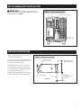
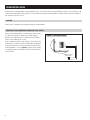
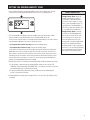
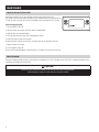
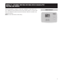
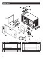
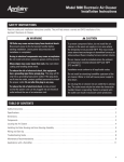
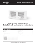
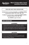
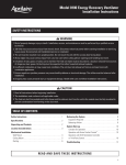
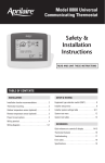
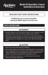
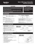
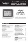
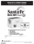
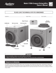
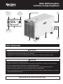
Model 1850F Dehumidifier
Installation and Operating Manual
ON/OFF button
used to turn
dehumidifier on
and off
Up/Down
buttons used to
change humidity
setting
Dehumidifer Control
Outlet
MODE button
used for optional
ventilation feature
Drain
Inlet
Power
Switch
Filter Access
Door
90-1952
Safety Instructions
WARNING
1. 120 Volts may cause serious injury from electric shock. Disconnect electrical power before starting installation or servicing.
Leave power disconnected until installation/service is completed.
2. Dropping may cause personal injury or equipment damage. Handle with care and follow installation instructions.
CAUTION
1. Read all instructions before beginning installation.
2. Improper installation may cause property damage or injury. Read instructions before installation, service or maintenance.
3. Do not use in pool applications. Pool chemicals can damage the dehumidifier.
4. Do not use solvents or cleaners on or near the circuit board. Chemicals can damage circuit board components.
5. Wait 24 hours before running the unit if it was not shipped or stored in the upright position
6. Do not use dehumidification to prevent window condensation in the winter. To address window condensation, use ventilation
to lower indoor humidity in the winter.
READ AND SAVE THESE INSTRUCTIONS
1
Table of Contents
Safety Instructions . . . . . . . . . . . . . . . . . . . . . . . . . . . . . . . . . . . . . . . . . . . . . . . . . . . . . . . . . . . . . . . . . . . . . . . . . . . . . . . . . . . . . . . . . . . . . . . . . . . . . 1
Specifications . . . . . . . . . . . . . . . . . . . . . . . . . . . . . . . . . . . . . . . . . . . . . . . . . . . . . . . . . . . . . . . . . . . . . . . . . . . . . . . . . . . . . . . . . . . . . . . . . . . . . . . . . 2
Set Up Dehumidifier for Installation . . . . . . . . . . . . . . . . . . . . . . . . . . . . . . . . . . . . . . . . . . . . . . . . . . . . . . . . . . . . . . . . . . . . . . . . . . . . . . . . . . . . . . 3
Location Considerations . . . . . . . . . . . . . . . . . . . . . . . . . . . . . . . . . . . . . . . . . . . . . . . . . . . . . . . . . . . . . . . . . . . . . . . . . . . . . . . . . . . . . . . . . . . . . . . . 3
Drain Installation . . . . . . . . . . . . . . . . . . . . . . . . . . . . . . . . . . . . . . . . . . . . . . . . . . . . . . . . . . . . . . . . . . . . . . . . . . . . . . . . . . . . . . . . . . . . . . . . . . . . . . 4
Leveling . . . . . . . . . . . . . . . . . . . . . . . . . . . . . . . . . . . . . . . . . . . . . . . . . . . . . . . . . . . . . . . . . . . . . . . . . . . . . . . . . . . . . . . . . . . . . . . . . . . . . . . . . . . . . . 4
Condensate Pan, Condensate Pump and Float Switch . . . . . . . . . . . . . . . . . . . . . . . . . . . . . . . . . . . . . . . . . . . . . . . . . . . . . . . . . . . . . . . . . . . . . . . . . 4
Setting the Desired Humidity Level . . . . . . . . . . . . . . . . . . . . . . . . . . . . . . . . . . . . . . . . . . . . . . . . . . . . . . . . . . . . . . . . . . . . . . . . . . . . . . . . . . . . . . 5
Maintenance . . . . . . . . . . . . . . . . . . . . . . . . . . . . . . . . . . . . . . . . . . . . . . . . . . . . . . . . . . . . . . . . . . . . . . . . . . . . . . . . . . . . . . . . . . . . . . . . . . . . . . . . . . 6
Model 76 – External Control or Crawl Space/Sealed Attic Control and Wiring . . . . . . . . . . . . . . . . . . . . . . . . . . . . . . . . . . . . . . . . . . . . . . . 7
Troubleshooting . . . . . . . . . . . . . . . . . . . . . . . . . . . . . . . . . . . . . . . . . . . . . . . . . . . . . . . . . . . . . . . . . . . . . . . . . . . . . . . . . . . . . . . . . . . . . . . . . . . . . . . . 8
Table 1 – Diagnostic Codes . . . . . . . . . . . . . . . . . . . . . . . . . . . . . . . . . . . . . . . . . . . . . . . . . . . . . . . . . . . . . . . . . . . . . . . . . . . . . . . . . . . . . . . . . . . . . . 8
Table 2 – Troubleshooting Guide . . . . . . . . . . . . . . . . . . . . . . . . . . . . . . . . . . . . . . . . . . . . . . . . . . . . . . . . . . . . . . . . . . . . . . . . . . . . . . . . . . . . . . . . . . 9
Service Parts . . . . . . . . . . . . . . . . . . . . . . . . . . . . . . . . . . . . . . . . . . . . . . . . . . . . . . . . . . . . . . . . . . . . . . . . . . . . . . . . . . . . . . . . . . . . . . . . . . . . . . . . . 10
Warranty . . . . . . . . . . . . . . . . . . . . . . . . . . . . . . . . . . . . . . . . . . . . . . . . . . . . . . . . . . . . . . . . . . . . . . . . . . . . . . . . . . . . . . . . . . . . . . . . . . . . . . . . . . . . . 11
Specifications
Model 1850F
Weight
Capacity
AHAM DH-1-2008 80°F, 60% RH Conditions
Power
115 VAC, Single Phase, 60Hz
Dehumidifier Inlet Air Conditions
Filter
Airflow
2
70 lbs.
95 pints per day @ 230 CFM
8A operating current
Dehumidification: 50°F – 104°F, 40°F dew point minimum
Ventilation: 40°F – 140°F, 0%RH – 99%RH (non-condensing)
MERV 8, washable
230 CFM
SET UP DEHUMIDIFIER FOR INSTALLATION
Figure 1 – Remove Shipping Bracket
REMOVE SHIPPING BRACKET
REMOVE AND DISCARD
SHIPPING BRACKET AND STRAP
BEFORE START UP.
IMPORTANT: Cut the strap securing the compressor
shipping support bracket and remove the strap, shipping bracket
screws, and bracket. See Figure 1.
CLIP OFF
PLASTIC STRAP
90-1944
LOCATION CONSIDERATIONS
•Allow sufficient clearance for filter removal and
to prevent airflow obstruction
•Electrical service access will require the removal
of the side panel shown. Allow sufficient space
for service on this side of the unit.
Figure 2 – Filter Access Clearance
ELECTRICAL SERVICE
ACCESS THIS SIDE
6" MINIMUM CLEARANCE
FOR PROPER AIR FLOW
•If locating the unit in an attic or crawl space, a
Model 76 Control mounted in the living space
is recommended. Refer to Model 76 Installation
Instructions and Owner’s Manual.
•Always install the dehumidifier in a condensate
pan when locating in or over a finished space.
6 FT. POWER CORD
FILTER
13" MINIMUM
CLEARANCE FOR FILTER
(EITHER SIDE)
TOP VIEW
90-1945
3
DRAIN INSTALLATION
The drain outlet on the dehumidifier can be hard piped using 3/4” nominal drain tubing or the provided fittings and 1/2” clear PVC tubing can be
used to drain the dehumidifier. Always maintain a constant downward slope from the dehumidifier to the drain and do not allow soft tubing to
curl up which may result in air lock.
LEVELING
A level surface is required to ensure proper drainage from the dehumidifier.
CONDENSATE PAN, CONDENSATE PUMP AND FLOAT SWITCH
Install a condensate overflow safety switch (i.e. float switch) in the
condensate pan, remove the factory installed jumper wire between
the Float Switch terminals on the control and wire the float switch
to the dehumidifier as shown in Figure 4. Overflow safety switches
on condensate pumps can be wired to the Float Switch terminals in
a similar fashion.
Figure 4 – Float Switch Wiring
FLOAT DH DH
Switch
Always install the dehumidifier in a condensate pan when locating
in or above a finished space. Adhere to local codes regarding
draining of the condensate pan. If a condensate pump is needed,
install it in the condensate pan as well.
NORMALLY CLOSED
FLOAT SWITCH
90-1857
4
Setting the Desired Humidity Level
1.Press the ON/OFF button to turn the dehumidifier control ON. The display will show the
current setting, and the dehumidifier blower will turn on to start sampling the air.
90-1853
2.The UP and DOWN arrow buttons allow the humidity level to be set from 40% to 80%
relative humidity. Use the ON/OFF button to turn the dehumidifier ON or OFF.
Set the control at 55%RH when first installed. Allow the dehumidifier to run until it reaches
the setting before deciding if you want to change the setting.
• If you prefer the air to be more dry, decrease the humidity setting.
• If you prefer the air to be less dry, increase the humidity setting.
Y
our comfort is the best measure of how to adjust your setting. When first installed, your
dehumidifier has to remove all the moisture that is initially in your home. The home acts
like a sponge so the moisture in the materials of your home is at the same level as the air.
After drying the air, the materials of the home will release moisture back into the air until
they are again at the same level. As a result, it is not uncommon for the dehumidifier to
operate for an extended period when first installed.
Energy Savings TipS
Energy Savings Tip #1: Adjust the
humidity setting to be as high as is
comfortable to reduce dehumidifier
run time. If it feels clammy or “smells
musty”, lower the humidity setting. To
save energy, turn the dehumidifier to
OFF when you open your windows, just
as you would with air conditioning.
Energy Savings Tip #2: If vacating
your home for an extended period in
the summer, set the RH at 55% and
set your thermostat as high as you
are comfortable setting it to in the
cooling mode. Consult with appropriate
professionals regarding the highest
temperature that is safe for your pets or
possessions. This will keep the humidity
at a controlled level while minimizing
the amount of cooling energy used.
3.After three (3) minutes of sampling, the measured humidity will be compared to the setting:
a. If the humidity is above the setting, the dehumidifier compressor turns on and “AIR
SAMPLING” will be replaced by “DEHUMIDIFYING”. The compressor remains on until the
measured humidity falls 3% RH below the setting.
b. If the measured humidity is below the setting, the blowers turn off and the display
returns to showing the RH setting.
4.The dehumidifier will sample again every 60 minutes, or at any time if the humidity setting
is lowered.
5
Maintenance
Clean or Replace the Air Filter
After initial installation the air filter should be checked and cleaned every 6 months.
The CLEAN FILTER service reminder will display on the on-board control screen every 6 months.
To clear the service message, press the UP and DOWN arrows simultaneously for 3 seconds.
Filter Cleaning Procedure
1.Turn the ON/OFF switch OFF.
2.Remove the filter access door from either side of the dehumidifier.
90-1854
3.Slide the filter out of the dehumidifier.
4.Flush the filter with warm water and a mild detergent solution.
5.Shake off the excess water from the filter.
6.Replace the filter, making sure the filter is secured in both the top and bottom filter rails.
7.Replace the filter access door.
8.Turn the ON/OFF switch ON.
9.Press the UP and DOWN buttons simultaneously for 3 seconds to clear the service message.
Check the Drain
The drain should be checked annually to ensure there are no blockages or air lock in the drain system. If the unit is not draining properly, have it
checked by a qualified service professional.
CAUTION
Do not use spray solvents or cleaners on or near the inlet side of the dehumidifier.
If desired, apply cleaner to a cloth and use to clean the cabinet.
6
MODEL 76 – EXTERNAL CONTROL OR CRAWL SPACE/SEALED ATTIC
CONTROL AND WIRING
When the dehumidifier is located in a crawl space, sealed attic, or other hard to access
area, a Model 76 can be installed in the living space and will operate as a remote control.
Refer to the Model 76 Installation Instructions and Owner’s Manual for installation and
operating instructions.
Model 76 Control
NOTE: Use 18-22 AWG wire for control wiring.
7
TROUBLESHOOTING
Technical Support is available Monday through Friday, 7:00 a.m. to 5:00 p.m. CST, at (800) 334-6011. Use the guides on the following pages to
identify and correct system faults. Contact Technical Support before replacing the unit or any components and for additional troubleshooting.
DIAGNOSTIC CODES
When an error occurs, the Diagnostic Code along with SERVICE REQUIRED
will be displayed on the control screen.
90-1854
TABLE 1 – Diagnostic Codes
Diagnostic
Code
8
Failure Mode
Action
Reset
E1
Internal Humidity or
Temperature Sensor
Open or Shorted
1.Check the connection between the sensor board and control board.
2. If connection okay, replace sensor board, Part No. 5460.
Cycle Power
E2
High Refrigeration
Pressure
1.Verify that the fan works, and that there is nothing restricting air flow.
2. If the fault persists, call Technical Support.
Cycle Power
E3
Model 76
Remote Control
Communication Loss
1.Check connections between Model 76 and dehumidifier control board. Terminals should be fully
inserted and secured in the control board and Model 76 control terminals.
2. If connections are correct and secure, turn off the dehumidifier and remove the Model 76. Use a
short section of 4-wire cable to reconnect the Model 76 to the control board. Turn the dehumidifier
back on and increase the dryness level setting on the Model 76. If the dehumidifier turns on, the
problem is with the wiring between the dehumidifier and control.
3. If the dehumidifier does not turn on, call Technical Support.
Self-Correcting
E4
Insufficient Capacity
1.Check the frost sensor connection at the power board. Terminal should be fully seated on the
power board pins.
2.Remove the side access panel and verify that the sensor is secured to the suction line.
3. If the sensor is connected and secured to the refrigeration line proceed to the next step.
4.Reset the fault by cycling power to the dehumidifier.
5.Turn the humidity setting down (below room/home humidity level) to make a dehumidification call.
6.Allow the fan and compressor to run for approximately 10-15 minutes and then enter diagnostic
test mode by simultaneously pressing the UP ARROW and MODE buttons for 3 seconds. The LCD
will display the temperature measured by the internal sensor while also displaying AIR SAMPLING
and ON, the humidity measured by the internal sensor while also displaying %RH and ON, and the
frost sensor temperature while also displaying ON. Scroll through these values and by using the
UP/DOWN arrow buttons.
7.Record values and call Technical Support.
Cycle Power
E5
High Temperature
Thermistor Failure
1.Check the high temperature sensor connection at the power board. Terminal should be fully seated
on the power board pins.
2.Remove the side access panel and verify the sensor is not damaged and connected to the
refrigeration line coming from the compressor.
3. If the sensor is connected and secured to the refrigeration line, it may need to be replaced with
Part No. 5456 – contact Technical Support to confirm.
Cycle Power
E6
Low Temperature
Thermistor Failure
1.Check the low temperature sensor connection at the power board.
2.Remove the side access panel and verify the sensor is not damaged and connected to the suction
line.
3. If the sensor is connected and secured to the refrigeration line, it may need to be replaced with
Part No. 5455 – contact Technical Support to confirm.
Cycle Power
TROUBLESHOOTING (continued)
TABLE 1 – Diagnostic Codes (continued)
Diagnostic
Code
Failure Mode
Action
Reset
E7
Float Switch Open
1.Empty the condensate pan.
2.Check the float switch connection at the control board.
3. If not using a float switch, verify jumper is between float switch terminals on dehumidifier
control board.
4. If the problem persists, replace the float switch.
Self-Correcting
E8
Inlet Air Temperature
Out of 50°F – 104°F
or dew point below
40°F
1. If temperature is out of range, no action, normal operation.
2. If air temperature is between 50°F –104°F with a dewpoint above 40°F, contact Technical
Support.
Self-Correcting
TABLE 2 – Troubleshooting Guide
Symptom
Possible Reason
Troubleshooting Procedure
Dehumidifier does not
turn on/run.
No power to unit.
• Check that the dehumidifier is plugged in.
• Check that the power switch is turned ON.
• Check that the control is turned ON.
• Check that the circuit breaker has not tripped.
Dehumidifier blower is
running but with little or
no airflow.
Pressure drop across dehumidifier
is higher than 0.6”w.c.
• Check dehumidifier air filter and wash or replace.
Dehumidifier blower is
running but compressor
is not.
Float switch open.
• If float switch installed, check connections at control board and empty condensate pan.
• If no float switch installed check that the jumper is installed at the float switch terminals
on the control board.
Coil frosting.
• Lack of or reduced airflow. Check dehumidifier air filter and wash or replace.
• Check that there is nothing blocking the inlet or outlet of the dehumidifier.
• Inlet air conditions below 60°F. Increase the humidity setting.
Inlet air temperature is outside of
the 50°F – 104°F range or the dew
point is below 40°F and there is a
demand for dehumidification.
• No action. The compressor will not run if inlet conditions are out of range.
Dehumidifier is not
draining properly.
Drain line blocked or unit not level.
• Verify that the unit is level.
• Check the drain line blockages and for a continuous downward slope.
Dehumidifier is
producing hot air.
Normal function.
• Air is reheated across the condenser coil, resulting in a temperature rise between inlet
and outlet.
9
SERVICE PARTS
12
4
3
1
6
8
2
9
11
5
7
90-1947
10
13
No.
10
Part Description
Part No.
No.
Part Description
Part No.
1
Filter, 12” x 12” x 1” EZK
5499
8
Sensor, Low Temperature, Deh
5455
2
Internal Control Board, Deh
5444
9
Sensor, High Temperature, Deh
5456
3
User Interface Assembly, Deh
5445
4
Wiring Access Door, AA Deh
5446
10
Capacitor, 45MFD, 370VAC, 70pt/95pt Deh,
(compressor)
5458
5
Door, Filter Access, AA Deh
5506
11
Capacitor, 12MFD, 450VAC, 95pt Deh, (fan)
5468
6
Fan, 95pt Deh
5467
12
RH Sensor, Deh
5460
7
Wire Harness, Power, Deh
5454
13
Drain Tube + Fittings
5461
Limited Warranty
Your Research Products Corporation Aprilaire® Dehumidifier is expressly warranted for five (5) years from date of installation to be free from defects in materials
or workmanship.
Research Products Corporation’s exclusive obligation under this warranty shall be to supply, without charge, a replacement for any component which is found to
be defective within such five (5) year period and which is returned not later than thirty (30) days after said five (5) year period by you to either your original supplier
or to Research Products Corporation, Madison, Wisconsin 53701, together with the model number and installation date of the dehumidifier.
THIS WARRANTY SHALL NOT OBLIGATE RESEARCH PRODUCTS CORPORATION FOR ANY LABOR COSTS AND SHALL NOT APPLY TO DEFECTS IN WORKMANSHIP
OR MATERIALS FURNISHED BY YOUR INSTALLER AS CONTRASTED TO DEFECTS IN THE DEHUMIDIFIER ITSELF.
IMPLIED WARRANTIES OF MERCHANTABILITY OR FITNESS FOR A PARTICULAR PURPOSE SHALL BE LIMITED IN DURATION TO THE AFORESAID FIVE YEAR
PERIOD. RESEARCH PRODUCTS CORPORATION’S LIABILITY FOR INCIDENTAL OR CONSEQUENTIAL DAMAGES, OTHER THAN DAMAGES FOR PERSONAL
INJURIES, RESULTING FROM ANY BREACH OF THE AFORESAID IMPLIED WARRANTIES OR THE ABOVE LIMITED WARRANTY IS EXPRESSLY EXCLUDED.
THIS LIMITED WARRANTY IS VOID IF DEFECT(S) RESULT FROM FAILURE TO HAVE THIS UNIT INSTALLED BY A QUALIFIED HEATING AND AIR CONDITIONING
CONTRACTOR. IF THE LIMITED WARRANTY IS VOID DUE TO FAILURE TO USE A QUALIFIED CONTRACTOR, ALL DISCLAIMERS OF IMPLIED WARRANTIES SHALL
BE EFFECTIVE UPON INSTALLATION.
Some states do not allow limitations on how long an implied warranty lasts or the exclusion or limitation of incidental or consequential damages so the above
exclusion or limitations may not apply to you.
This warranty gives you specific legal rights and you may also have other rights which vary from state to state.
WARRANTY REGISTRATION
Visit us on-line at www.aprilaire.com to register your Aprilaire product. If you do not have on-line access, please mail a postcard with your
name, address, phone number, email address, product purchased, model number, date of purchase and dealer name and address to:
Research Products Corporation, P.O. Box 1467, Madison, WI 53701
Your Warranty Registration information will not be sold or shared outside of this company.
11
P.O. Box 1467 • Madison, WI 53701-1467 • Phone: 800/334-6011 • Fax: 608/257-4357 • www.aprilairepartners.com
10010677 3.14
B2206280A
Printed in U.S.A.
© 2014 Aprilaire – A division of Research Products Corporation