1
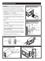
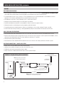
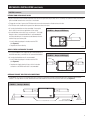
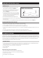
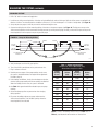
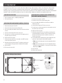
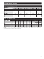
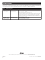
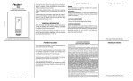
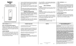
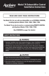
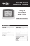
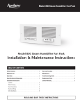
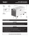
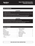
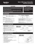
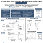
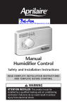
Model 8100 Energy Recovery Ventilator
Installation Instructions
Safety Instructions
WARNING
1. Risk of property damage, injury or death. Installation, service, and maintenance must be performed by a qualified service
technician.
2. 120 Volts may cause serious injury from electric shock. Disconnect electrical power before starting installation or servicing.
Leave power disconnected until installation/service is completed.
3. The unit must be mounted in an upright position. Do not mount the unit with the access door facing down.
4. Sharp edges may cause serious injury from cuts. Use care when cutting plenum openings and handling duct work.
5. Inhalation of toxic gases or fumes can be harmful. The fresh air intake must be mounted in a location removed from sources
of dangerous toxic gases. All ducting must be separate from other household exhaust systems.
6. Insufficient combustion air may cause toxic conditions. The unit must not exhaust air from an enclosed room with
combustion appliances.
7. Excess negative or positive pressure may cause health problems or structural damage. The airflow must be balanced after
installation.
8. Dropping may cause personal injury or equipment damage. Handle with care and follow installation instructions.
CAUTION
1. Read all instructions before beginning installation.
2. The installation must conform to all applicable codes.
3. The fresh air duct from outside and to the house and the stale air duct from the unit to the outside must be fully insulated to
prevent condensation from forming on the duct work.
Table of Contents
Safety Instructions . . . . . . . . . . . . . . . . . . . . . . . . . . . . . . . . . . . . . . . 1
Specifications . . . . . . . . . . . . . . . . . . . . . . . . . . . . . . . . . . . . . . . . . . . 2
Unpacking and Contents . . . . . . . . . . . . . . . . . . . . . . . . . . . . . . . . . . 2
Location Considerations . . . . . . . . . . . . . . . . . . . . . . . . . . . . . . . . . . 3
Mechanical Installation
Wall Mount . . . . . . . . . . . . . . . . . . . . . . . . . . . . . . . . . . . . . . . . . . . . . 4
Ceiling Mount . . . . . . . . . . . . . . . . . . . . . . . . . . . . . . . . . . . . . . . . . . . 5
Ducting . . . . . . . . . . . . . . . . . . . . . . . . . . . . . . . . . . . . . . . . . . . . . . . . 6
Balancing the System . . . . . . . . . . . . . . . . . . . . . . . . . . . . . . . . . . . . 8
Equipment Required . . . . . . . . . . . . . . . . . . . . . . . . . . . . . . . . . . . . . . 8
Balancing Airflow . . . . . . . . . . . . . . . . . . . . . . . . . . . . . . . . . . . . . . . . 9
System Start-up . . . . . . . . . . . . . . . . . . . . . . . . . . . . . . . . . . . . . . . . .
Constant On Operation . . . . . . . . . . . . . . . . . . . . . . . . . . . . . . . . . . .
Operation with Home Comfort Control™ . . . . . . . . . . . . . . . . . . . . .
Operation with 8120 Ventilation Controller
or Third-Party Control . . . . . . . . . . . . . . . . . . . . . . . . . . . . . . . . . . . .
10
10
10
10
Troubleshooting . . . . . . . . . . . . . . . . . . . . . . . . . . . . . . . . . . . . . . . . . 12
READ AND SAVE THESE INSTRUCTIONS
1
Specifications
Dimensions
Unit – 37-7/16” W x 12-3/4” D x 20-9/16” H
EnergyMax Transfer Core – 12-1/8” x 12-1/8” x 10-3/4”
Weight
75 lbs.
Performance
77% Apparent Sensible Effectiveness (ASE)
At rated ventilation capacity with 72°F indoor temperature and 32°F outdoor temperature.
Capacity
Maximum home size per ASHRAE Standard 62.2-2010* with continuous operation at rated airflow:
4-5 bedrooms – 7,500 ft2, 6-7 bedrooms – 6,000 ft2, 7+ bedrooms – 4,500 ft2.
*No infiltration credit assumed. Refer to the standard for details on required ventilation rates.
Power
120 VAC, 1.4 Amp maximum. Unit equipped with 3 ft. grounded power cord.
Filter
Two 10-13/16” x 11-5/16” x 3/32” EZ Kleen air filters. Filters coated with Super Filter Coat adhesive.
Airflow
120 cfm at 0.30” w.c. external pressure.
UNPACKING AND CONTENTS
1.Open one end of the carton.
2.Remove the cardboard inner pack.
Figure 1 – Opening View and Contents
3.See Figure 1 for carton contents.
a. Inner pack
b. Energy Recovery Ventilator
c. Installation Instructions
d. Owner’s Manual
e. Mounting Hardware Carton
MOUNTING HARDWARE
OWNERS MANUAL
INSTALLATION MANUAL
ENERGY RECOVERY VENTILATOR
4.See Figure 2 for contents of mounting
hardware carton.
a. Mounting Bracket
b. Hanging Hook Bracket
c. Hanging Hinge Bracket
d. H
anging Pins and Threaded Nuts
e. M
achine Screws
f. Lag Bolts and Washers
INNER PACK
90-1751
Figure 2 – Mounting Hardware
HANGING HOOK BRACKET
HANGING HINGE BRACKET
MOUNTING BRACKET
WASHERS
LAG BOLTS
HANGING PINS
THREADED NUTS
MACHINE SCREWS
90-1739
2
LOCATION CONSIDERATIONS
1.Install Unit Indoors: It is recommended that the Model 8100 ERV be mounted in a conditioned space. If the unit is mounted in an area where
the temperature may drop below 32°F or exceed 100°F, all duct work in the unconditioned space must be insulated.
2.Mounting: The recommended mounting location is on the basement foundation wall, or a stud wall with easy access to the HVAC system.
The unit may also be mounted to basement ceiling joists.
3.Mounting Kit: The unit must be mounted with the mounting kit provided.
4.Power: Outlet within 30” of unit.
5.Service Clearances: Allow a minimum of 36” clearance around the access door. Allow for 12” of clearance to access duct connections, on/
off switch and wiring connections. (See Figure 3.)
Figure 3 – Dimensions and Location Considerations
EXTERNAL CONTROL WIRING ACCESS
CEILING MOUNTING HOLES
CEILING MOUNTING HOLES
ON / OFF
SWITCH
RETURN
STALE AIR
WALL
MOUNTING
HOLES
WALL
MOUNTING
HOLES
20-9/16"
SUPPLY
FRESH AIR
6" ROUND
COLLARS
2"
2"
12-3/4"
37-7/16"
6" ROUND COLLARS
12"
12"
SERVICE
CLEARANCE
36"
90-1743
3
MECHANICAL INSTALLATION
WALL MOUNT
Figure 4 – Removing Core and Filters
The unit can be mounted on a concrete wall or on a stud wall. The mounting
bracket is pre-drilled for fastening to standard 16” O.C. or 24” O.C. stud spacing.
Remove the access panel, EnergyMax Transfer Core, and air filters for installation.
1.Remove the access panel, EnergyMax Transfer Core and filters. (See Figure 4.)
2. For Stud Wall: Fasten the supplied mounting bracket to the wall using the
supplied lag bolts and washers. (See Figure 5.)
For Concrete Wall: Fasten the supplied mounting bracket to the wall using
field supplied concrete anchors and the supplied lag bolts and washers.
3.Insert the supplied hanging pin in the left hole of the mounting bracket and
secure by inserting the supplied washer and hand tightening with the supplied
nut. (See Figure 5.)
4.Insert the supplied hanging pin in the right hole of the mounting bracket. (See
Figure 5.)
5.Fasten the hanging hook bracket to the left side of the unit with the supplied
10-32 x 3/8” machine screws, using the pre-tapped holes along the side of the
unit. (See Figure 6.)
6.Fasten the supplied hanging hinge bracket to the right side of the unit with
the supplied 10-32 x 3/8” machine screws, using the pre-tapped holes along
the side of the unit. (See Figure 6.)
7.Pick the unit up and hook the hanging hook bracket on the left hanging pin.
(See Figure 7.) Note: Keep pressure against the unit to prevent it from
swinging away from the wall.
8.Push the unit against the bracket, remove the right side pin, align the hanging
hinge hook with the bracket and reinsert the hanging pin. Secure the pin by
inserting the supplied washer and tightening the supplied nut. (See Figure 8.)
9.Securely tighten the nut on the left side of the unit.
10.Reinstall the EnergyMax Transfer Core, air filters and access panel.
ENERGYMAX
TRANSFER CORE
FILTER
FILTER
90-1741
Figure 5 – Installing Mounting Bracket
on Wall
HANGING PIN
HANGING PIN
MOUNTING BRACKET
LAG BOLT
AND WASHER
WASHER
THREADED NUT
90-1735
Figure 6 – Installing Mounting Brackets
MACHINE SCREWS
HINGE BRACKET
HOOK BRACKET
(hook points out)
HINGE BRACKET
(hinge points out)
MACHINE SCREWS
LEFT END
RIGHT END
HOOK BRACKET
Figure 7 – Hanging Left Side of ERV
HANGING
PIN
90-1734
Figure 8 – Hanging Right Side of ERV
MOUNTING
BRACKET
HANGING PIN
MOUNTING BRACKET
HOOK BRACKET
HINGE BRACKET
WASHER
THREADED NUT
HINGE BRACKET
90-1742
4
90-1736
MECHANICAL INSTALLATION (continued)
CEILING MOUNT
Figure 9 – Removing Core and Filters
The unit can be mounted on ceiling joists. The mounting bracket is pre-drilled
for fastening to standard 16” O.C. or 24” O.C. ceiling joists. Remove the access
panel, EnergyMax Transfer Core, and air filters for installation. CAUTION: Do
not mount the ERV to ceiling I-beam wood trusses.
1.Remove the access panel, EnergyMax Transfer Core and filters. (See Figure 9.)
2.Fasten the supplied mounting bracket to the ceiling joists using the supplied
lag bolts and washers. (See Figure 10.)
3.Insert the supplied hanging pin in the left hole of the mounting bracket
and secure by inserting the supplied washer and hand tightening with the
supplied nut. (See Figure 10.)
4.Insert the supplied hanging pin in the right hole of the mounting bracket. (See
Figure 10.)
5.Fasten the hanging hook bracket to the top of the left side of the unit with
the supplied 10-32 x 3/8” machine screws, using the pre-tapped holes along
the side of the unit. (See Figure 11.)
6.Fasten the supplied hanging hinge bracket to the right side of the unit with
the supplied 10-32 x 3/8” machine screws, using the pre-tapped holes along
the side of the unit. (See Figure 11.)
7.Pick the unit up and hook the hanging hook bracket on the hanging pin. (See
Figure 12.) Note: Keep pressure against the unit to prevent it from
swinging away from the ceiling.
8.Push the unit up against the bracket, remove the right side pin, align the
hanging hinge hook with the bracket and reinsert the hanging pin. Secure the
pin by inserting the supplied washer and tightening the supplied nut. (See
Figure 13.)
9.Securely tighten the nut on the left side of the unit.
10.Reinstall the EnergyMax Transfer Core, air filters and access panel.
ENERGYMAX
TRANSFER CORE
FILTER
FILTER
90-1741
Figure 10 – Installing Mounting Bracket
on Ceiling
WASHER
THREADED NUT
HANGING PIN
LAG BOLT
AND WASHER
HANGING PIN
90-1737
Figure 11 – Installing Mounting Brackets
HOOK BRACKET
(hook points out)
HINGE BRACKET
(hinge points out)
LEFT END
90-1740
Figure 13 – Hanging Right Side of ERV
CEILING JOISTS
HOOK BRACKET
INSTALL HINGE ONTO
APRILAIRE Energy
Recovery Ventilator
RIGHT END
Figure 12 – Hanging Left Side of ERV
HANGING PIN
INSTALL HOOK ONTO
APRILAIRE Energy
Recovery Ventilator
MOUNTING BRACKET
HANGING PIN
MOUNTING BRACKET
THREADED NUT
HINGE BRACKET
WASHER
HINGE BRACKET
90-1744
90-1745
5
MECHANICAL INSTALLATION (continued)
DUCTING
Duct work Specifications
•Plan on temporarily installing two air flow measuring devices. The system will have to be balanced (BALANCING THE SYSTEM SECTION),
after all duct work has been installed. The measuring devices are removed after the system has been balanced.
•A sound absorber at least 6 ft. long, consisting of 1” thick rigid fiberglass duct or insulated flexible duct is recommended for maximum
absorption of air movement sounds between the unit and the living space return grille.
•All flexible ducts must meet UL safety standards for Class 1 air ducts and connectors.
•All ducting must be installed according to local HVAC codes and standards.
•Round 6” galvanized duct or equivalent is recommended for all duct runs that do not require insulation.
•All ducting located in an unheated space must be completely sealed and insulated.
•For optimum performance and quite operation, all duct runs should be kept as short, straight, and equal in length as possible.
•If the ERV will not be running continuously, a field supplied butterfly damper must be installed in the intake duct near the hood.
GrillE and Hood Specifications
•The living space return grille should not be less than 75 in2 of free area. Grille surfaces less than this may produce excess air noise.
•Exterior intake and exhaust hoods must be weather resistant. The hoods must also incorporate a screen to prevent unwanted debris, animals,
and insects from entering the duct work. The screen should have a maximum of ¼” openings.
•Caulk both hoods to prevent water leakage.
•Intake and exhaust hoods should be above the expected snow line or a minimum of 18” above ground level, whichever is greater.
Duct work Connections – ForceD Air System
•All duct collars are clearly labeled and must be connected properly.
•Rigid duct work should be connected to the collars with sheet metal screws.
•Flexible duct work must be connected with clamps or bands.
•All duct connections should be sealed with duct tape or mastic to prevent leakage.
Figure 14 – Fully Ducted Energy Recovery Ventilator
STALE AIR FROM HOUSE
(CENTRALLY LOCATED SUCH AS HALLWAY)
NOTE: FRESH AIR INLET TO RETURN DUCT
10 FEET MINIMUM FROM HVAC BLOWER.
AIR MOVEMENT
SOUND ABSORBER
FRESH AIR TO HOUSE
STALE AIR FROM HOUSE
STALE AIR TO OUTSIDE
FRESH AIR FROM OUTSIDE
BUTTERFLY DAMPER
(IF ERV NOT RUNNING CONTINUOUSLY)
10 FT MINIMUM
NOTE: THE FRESH AIR INTAKE SHOULD BE INSTALLED
A MINIMUM OF 10 FEET FROM ANY EXHAUST VENT.
90-1747
6
MECHANICAL INSTALLATION (continued)
DUCTING (continued)
RETURN: From Living Space to ERV
•Stale air from the house should be exhausted from one exhaust grille centrally located, such as a hallway. For multi-floor homes, the exhaust
grille should be located on the same floor as the kitchen.
•To keep the core free of grease, the ERV duct work must not be connected to a kitchen exhaust fan duct.
•The ERV duct work should remain separate from bathroom exhaust fan ducts.
•6” round, galvanized duct work recommended. If rectangular
duct is used, it must have an equivalent air flow rating.
Figure 15 – Damper in ERV Return
•A sound absorber at least 6 ft. long, consisting of 1” thick rigid
fiberglass duct or insulated flexible duct is recommended for
maximum absorbing of air movement sounds between the unit
and the living space return grille.
DAMPER
1. Install a balancing damper in the duct near the ERV.
(See Figure 15.)
2. Complete the Return ducting.
90-1747
SUPPLY: Fresh Air From ERV to House
•It is recommended that the supply duct be connected directly to
the HVAC return duct, a minimum of 10’ from the HVAC blower.
Figure 16 – Damper in ERV Supply
•6” round, galvanized duct work is recommended.
1. Install a balancing damper in the duct near the ERV.
(See Figure 16.)
DAMPER
DAMPER
2. Complete the Supply ducting. Using a collar for the duct
connection to the HVAC return duct is recommended.
90-1753
OUTDOOR: Exhaust and Fresh Air Connections
•Insulated duct of at least R-4 insulating value with a continuous vapor barrier must be used for both duct runs connecting the ERV to the
outdoors. The vapor barrier must be sealed at both ends and extend from the ERV housing to the outer wall. (See Figure 17.)
Figure 17 – Ducting to Outdoors
STALE AIR
TO OUTSIDE
INSULATED DUCT
BUTTERFLY DAMPER
(IF ERV NOT RUNNING CONTINUOUSLY)
FRESH AIR
FROM OUTSIDE
90-1747
7
MECHANICAL INSTALLATION (continued)
DUCTING (continued)
•The intake and exhaust hoods must be located at least 10 ft.
apart to avoid cross contamination. (See Figure 18.)
Figure 18 – Intake and Exhaust Hoods
•Intake and exhaust hoods should be above the exposed snow
line or a minimum of 18” above ground level, whichever is
greater. (See Figure 18.)
•The intake hood should be a minimum of 10 ft. from an appliance
vent that exhausts toxic fumes. The hood should not be installed
near sources of pollution and/or extreme temperatures, such as
furnace exhaust, car exhaust, dryer vents, etc.
INTAKE
18 INCHES
MINIMUM
EXHAUST
10 FT MINIMUM
GROUND
90-1748
•Do not connect the ERV exhaust to any gas appliance flue.
•Do not connect the exhaust outlet into an attic, storage or garage space. Excess moisture could develop in these areas, possibly causing
damage to the home.
•If not running continuously, a field supplied butterfly damper must be installed in the intake duct near the hood. (See Figure 17.)
Duct work Connections Without Forced Air
•All the ducting connection procedures apply, with the exception of the following changes:
•The fresh air supply can be ducted to various parts of the home, where fresh air is needed.
•It is recommended that no more than 3 fresh air supply ducts be used to assure adequate airflow.
•The total free area of supply grilles should not be less than 75 in2. For example: Three supply ducts would require a minimum of 25 in2 of free
area each.
•Do not place a supply outlet in the same room or in the vicinity of the stale air return from the house.
•It is recommended that the fresh air supply be in a hall or foyer to avoid drafts and blower noise in occupied areas.
BALANCING THE SYSTEM
In order for the ERV to perform effectively, the volume of fresh air supplied to the house must match the volume of stale air exhausted. Because the
duct work in the two airstreams will most likely be different, the system must be balanced. Balancing is accomplished by installing dampers in both
airstreams, measuring the airflow, and dampering down the airflow in the stream with the highest flow, until the airflow in both streams is the same.
The following procedure is the recommended method. Other measuring instrumentation may be used if it is accurate enough to balance the
airflow in the supply and exhaust streams to within 10% of each other.
Equipment Required
•Two Dwyer Magnahelic Differential Pressure Gauges; Series 2000, 0-0.25” w.c. (or equal). Note: Do not use a standard differential pressure
gauge that reads above 0.25” w.c. The reading will not be accurate for the airflow required by the ERV.
•Two Research Products’ airflow measuring devices, Part Number 5158.
•3/16” ID flexible tubing.
•Drill with 7/8” bit.
Before balancing the system, verify the following:
1.Make sure the EnergyMax Transfer Core and filters are installed correctly.
2.Check all duct work connections to be sure they are installed and sealed properly.
3.Fasten door securely to housing.
4.Place all dampers in the fully open position.
8
BALANCING THE SYSTEM (continued)
Balancing Airflow
1.Drill a 7/8” hole in the return and supply ducts.
2.Install the two airflow measuring devices in the duct using the drilled holes and seal with tape. Verify the airflow arrows are pointed in the
direction of airflow. The measuring devices should be a minimum of 2-1/2’ from the damper in a 5’ section of straight duct. (See Figure 19.)
3.Set up the pressure gauges so that they are vertical and level and adjust to zero.
4.Connect the tubing from the airflow measuring devices in the ducts to the pressure gauges (see Figure 19). The high pressure tap on the
airflow measuring device must be connected to the high pressure tap on the pressure gauge. Similarly, connect the low pressure tap on the
measuring device to the low pressure tap on the pressure gauge.
Figure 19 – Set-up for Balancing Airflow
5 FT. MIN.
2-1/2 FT
DAMPER
DAMPER
2-1/2 FT
5 FT. MIN.
FRESH AIR
TO HOUSE
STALE AIR
FROM HOUSE
STALE AIR
TO OUTSIDE
FRESH AIR
FROM OUTSIDE
AIR FLOW MEASURING
DEVICE #5158
AIR FLOW MEASURING
DEVICE #5158
PRESSURE GAUGES
90-1746
5.Verify the dampers are in the fully open position.
Table 1 – Airflow Approximations
Airflow in a 6” Duct as Measured using
Airflow Measuring Device #5158
6.Turn off the HVAC system blower and any other exhaust fans.
7.Plug in and turn on the unit.
Gauge
Readings
(in. w.c.)
Airflow
(cfm)
Gauge
Readings
(in. w.c.)
Airflow
(cfm)
0.005
30
0.065
119
9.If the readings are different, slowly close the damper on the duct
with the higher gauge reading until the two readings are identical.
When the readings are the same, the system is balanced.
0.010
44
0.070
124
0.015
55
0.075
128
10.See Table 1 for approximated airflow based on pressure gauge
readings.
0.020
64
0.080
132
0.025
72
0.085
137
11.Secure the damper positions to prevent them from changing
during operation.
0.030
80
0.090
141
0.035
86
0.095
145
12.Disconnect the tubing and pressure gauges and remove the
airflow measuring devices. Seal the duct openings where the
measuring devices were located.
0.040
93
0.1
149
0.045
98
0.105
152
0.050
104
0.110
156
0.055
109
0.115
160
0.060
114
0.120
163
8.Read the pressure gauges. If the gauge readings are the same,
the system is balanced and does not require further adjustment.
Proceed to Step 10.
NOTE: If airlow is restricted by more than 20% (see bold values in
Table 1), check ductwork and connections to increase flow.
9
SYSTEM START-UP
The Energy Recovery Ventilator has an on/off switch which enables the unit to be constantly on. There is also wiring access and wire leads
available in the unit for connection to the Aprilaire Home Comfort Control™, Aprilaire Model 8120 Ventilation Controller, or any third-party
24VAC, dry contact, normally open external control to allow the unit to provide fresh air when needed in accordance with the 62.2-2010 ASHRAE
Standard. The 62.2-2010 ASHRAE Standard uses home size and the number of bedrooms to determine the required ventilation rate.
Constant On Operation
Operation With 8120 Ventilation Controller or
Third-Party Control (Figure 20)
1.Plug in the power cord to a 120VAC grounded outlet.
2.Turn on/off switch on.
1.Remove the front panel of the ERV.
2.Remove the wire nut from the two yellow wires.
Operation With Home Comfort Control™ (Figure 20)
3.Run 2-wire cable (18-24 AWG) from the ERV to the 8120 or
Third-Party Control.
1.Remove the front panel of the ERV.
4.Insert the wire through the ERV wire access port.
2.Remove the wire nut from the two yellow wires.
5.Use wire nuts to connect each end of the 2-wire cable to each of
the yellow wires from the ERV.
3.Run 2-wire cable (18-24 AWG) from the ERV to the Home Comfort
Control™.
4.Insert the wire through the ERV wire access port.
5.Use wire nuts to connect each end of the 2-wire cable to each of
the yellow wires from the ERV.
6.Replace the ERV front panel.
7.Connect the other end of the 2-wire cable to the VENT terminals
of the Home Comfort Control™.
8.Reference the Home Comfort Control™ Installation Instructions to
set the ventilation timing per the 62.2-2010 ASHRAE Standard.
9.Plug in the ERV.
10.Turn the on/off switch ON.
6.Replace the ERV front panel.
7.Connect the other end of the 2-wire cable to the A/A terminals
of the 8120 Ventilation Controller. If using a Third-Party Control,
reference the Third-Party Control Installation Instructions to
connect to the control.
8.Use the tables below to determine the airflow requirement and
cycle time to meet the 62.2-2010 ASHRAE Standard.
a. Table 2 on the following page shows the required ventilation
rate in CFM.
b. Table 3 on the following page shows the required ventilation
cycle time in minutes based on a 1 hour cycle using the airflow
determined in Table 1.
9.Plug in the ERV.
10.Turn the on/off switch ON.
Figure 20 – Wiring to External Control
APRILAIRE MODEL 8120
VENTILATION CONTROLLER
A/A
OR
VENT
VENT
YELLOW WIRES
TRANSFORMER
RELAY
HOME COMFORT CONTROL™
OR
THIRD-PARTY CONTROL,
24 VAC, DRY CONTACT,
NORMALLY OPEN
90-1749
10
SYSTEM START-UP (continued)
Table 2 – Ventilation Air Requirements, CFM
Number of Bedrooms
Home Size (ft2)
<2
2-3
4-5
6-7
>7
≤ 1500
30
45
60
75
90
1501 – 3000
45
60
75
90
105
3001 – 4500
60
75
90
105
120
4501 – 6000
75
90
105
120
135
6001 – 7500
90
105
120
135
150
> 7500
105
120
135
150
165
Table 3 – Cycle Time Setting (minutes)
CFM Required (from Table 2)
CFM Delivered
(refer to Table 1)
20
30
40
50
60
70
80
90
100
100
15
20
25
30
35
40
50
55
60
120
10
15
20
25
30
35
40
45
140
10
15
15
20
25
30
35
160
10
10
15
20
25
25
30
110
120
50
55
60
40
45
50
55
35
40
45
50
Example: For a 4,000 ft2 home with 5 bedrooms, the required mechanical ventilation rate from Table 2 is 90 cfm. If the ERV is operating at 120
cfm, set the cycle time on the control for at least 45 minutes/hour.
11
TROUBLESHOOTING
Technical Support is available Monday through Friday, 7:00 a.m. to 5:00 p.m. CST, at (800) 334-6011. Use the guide below to help find and correct
system faults and then contact Technical support before replacing the unit or components or for additional troubleshooting.
Table 4 – Troubleshooting Guide
Symptom
Possible Reason
Troubleshooting Procedure
ERV will not turn on.
No power to blower.
• Check that the ERV is plugged in.
• Check that the power switch on the ERV is ON.
• If wired to an external control, verify wire connections inside ERV and at control.
• Connect the two yellow wires in the ERV. If the blower turns on, the problem
resides with the external control. Troubleshoot the control in accordance with
the manufacturer’s instructions.
ERV blower is running,
but little or no airflow.
Incorrect damper position.
• Verify that the dampers are not closed.
• Check for blocked duct work and clear.
P.O. Box 1467 • Madison, WI 53701-1467 • Phone: 800/334-6011 • Fax: 608/257-4357 • www.aprilairepartners.com
10009736 1.12
B2701202A
12
Printed in U.S.A.
© 2012 Aprilaire – A division of Research Products Corporation