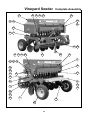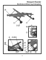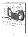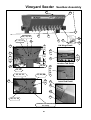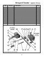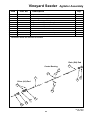
1
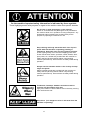
Owners Manual
Vineyard Seeder
From Serial Number 07184
Head Office:
P.O. Box 2018
Hilton Highway, Washdyke
Timaru, New Zealand
Telephone (03) 688 2029
Facsimile (03) 688 2821
Australian Branch:
4B SIlverton Close
Laverton North 3026
Melbourne, Australia
Telephone (03) 9314-9666
Facsimile (03) 9314-6810
Pt. No. 67372
Issue 0207
Vineyard Seeder
Contents
Page
Introduction
Acquisition and Warranty . . . . . . . . . . 2
The Owner’s Manual . . . . . . . . . . . . . . 2
Description of Machine
Working Principle . . . . . . . . . . . . . . . . 3
Specification
............................... 3
SAFETY - General
SAFETY - Machine Specific
Safety Symbols on Machine . . . . . . . .
Operator Safety . . . . . . . . . . . . . . . . . .
Be Prepared for Emergencies . . . . . .
Appropriate Dress . . . . . . . . . . . . . . . .
Transport This Machine Safely . . . . . .
Handle Agricultural Chemicals Safely .
Avoid High Pressure Fluids . . . . . . . . .
Safe Work Practices . . . . . . . . . . . . . .
Practise Safe Maintenance . . . . . . . . .
Hazard Points . . . . . . . . . . . . . . . . . . .
Safety Decals & Safety Guards . . . . .
4
5
5
6
6
7
7
7
8
9
11
Transport
. . . . . . . . . . . . . . . . . . . . . . . . . . . . . . 12
Operation
. . . . . . . . . . . . . . . . . . . . . . . . . . . . . . 12
Sowing Chart
. . . . . . . . . . . . . . . . . . . . . . . . . . . . . . 14
Basic Calibration Procedure
Gearbox Setting Lever . . . . . . . . . . . .
Setting Seeder Shutter Slides . . . . . . .
Bottom Flap Settings . . . . . . . . . . . . .
Seed Calibration . . . . . . . . . . . . . . . . .
Recalculating the Constant . . . . . . . . .
Use of Seed Rate Calculator . . . . . . .
Calibration Deviations . . . . . . . . . . . . .
Sowing of Fine Seeds . . . . . . . . . . . . .
Sowing Small Seeds . . . . . . . . . . . . . .
Sowing Peas . . . . . . . . . . . . . . . . . . . .
Hectaremeter Settings . . . . . . . . . . . .
Calibration Notes . . . . . . . . . . . . . . . .
15
15
15
16
18
18
19
20
21
22
22
24
Maintenance & Care
General . . . . . . . . . . . . . . . . . . . . . . . .
Lubrication . . . . . . . . . . . . . . . . . . . . .
Maintenance Schedule . . . . . . . . . . . .
Storage . . . . . . . . . . . . . . . . . . . . . . . .
Maintenance Notes . . . . . . . . . . . . . . .
25
26
27
29
30
Parts Lists
. . . . . . . . . . . . . . . . . . . . . . . . . . . . . . . 31
1
Pt. No. 67372
Issue 0207
Introduction
Acquisition & Warranty
On delivery of your new Duncan Ag Vineyard Seeder please
check that the machine is not damaged. In cases of shipping
damage, please ask your dealer to arrange for the appropriate
claim to be lodged immediately. Assemble any parts supplied
loose and inspect your machine with the aid of this manual to
familiarise yourself with its features. If you have any queries
ask your dealer straight away. The machine is covered by our
12 month warranty on faulty parts, subject to normal use.
Record below the serial number of your machine and keep
it in a secure place to help trace the machine and assist
us when you order parts.
Model: . . . . . . . . . . . . . . . . . . . . . . . . . . . . . . . . . . . . . .
Serial No: . . . . . . . . . . . . . . . . . . . . . . . . . . . . . . . . . . .
Owner: . . . . . . . . . . . . . . . . . . . . . . . . . . . . . . . . . . . . . .
.............................................
.............................................
Delivery Date: . . . . . . . . . . . . . . . . . . . . . . . . . . . . . . .
Dealer: . . . . . . . . . . . . . . . . . . . . . . . . . . . . . . . . . . . . . .
.............................................
.............................................
The Owner’s Manual
Your new Duncan Ag Vineyard Seeder will give long and
efficient service if given normal care and operated properly.
This owner’s manual is provided so that you can become
thoroughly familiar with the design of the machine and to
furnish information on correct operation, adjustment and
maintenance. Only persons well acquainted with these
guidelines should be allowed to use the equipment.
A separate illustrated parts section has been provided so that if
any parts are required your dealer will be able to supply them
by reference to part numbers.
The manual is considered as part of your machine and must
remain with the machine when it is sold.
Right and left hand references in this manual are determined
by standing behind the machine and facing in the direction
of travel.
2
Disclaimer
Every effort has been made to
ensure that the information in this
manual was accurate and up to
date at the time of going to press.
Clough Agriculture Ltd reserves the
right to make subsequent changes
to the machine, where necessary,
without notification.
The Company will not be
responsible for any damage or
consequential loss arising out of
misinterpretation or failure to follow
recommended procedures. Nor will
it be liable for any damage caused
by or arising out of modification or
misuse of its product.
The owner has a responsibility to
protect himself and others by
observing all safety information
and by ensuring all operators are
well acquainted with the safety
information, trained in the correct
use of the machine and applying
safe work practices.
Description of Machine
The Duncan Ag Vineyard Seeder is either a single
curved disc or double disc drill with dual boxes for
seed and fertilizer. The drill is carried and
operated from the three point linkage of the
tractor. The sowing depth control is achieved from
two trailing wheels with individual wheel retraction
stops. The right hand depth control wheel is also
the drive wheel for the seeder unit. A wide variety
of seeds can be sown from the seed box, from
small seeds like turnip and rape to large seeds
like peas and maize. The machine has a
calibration system for setting seeding rates prior
to operating, which is very simple and accurate to
use.
Working Principle
The gearbox, pegged seed rollers and seeder
flaps are set to give the desired seed rate. The
disc(s) create the seed bed. Seed flows down the
flexible tubes between the seeder and the coulter
casting units, and drops into the prepared seed
bed.
Specification
Table 1
Dimensions & Capacities
Width Over Frame
Length Overall
Height (Depth Wheels Up)
Weight (Unladen)
Depth Wheel Tyre Size
Tyre Pressure (Max)
Row Spacing
Sowing Width
Box Capacity (per box)
1835mm
1800mm
1520mm
710kg
155R13
2.4 bar (35 psi)
180mm
1800mm
209 litres
Estimated weight excludes press wheels
Pt. No. 67372
Issue 0207
3
!
ATTENTION
On the machine important safety information is indicated by these symbols.
These highlight general safety aspects in regard to the machine rather than specific hazards.
Do not ride or allow passengers on the machine.
Under no circumstances are passengers to be permitted on
the machine while it is in operation or being transported. Any
footboards and/or footsteps are provided solely for the
purpose of preparing the machine for use.
Keep clothing and body extremities well clear of pinch
points while the machine is operating (seeding or
calibrating). Keep well clear of moving parts at all times.
These signs typically occur wherever trapping points exist.
These include drive chains, sprockets, shafts, wheels, discs,
pivot points, etc. Guards are provided with the machine for
safety reasons (where practical without compromising
machine performance). Ensure these are always fitted during
operation.
Always exercise extreme caution in the vicinity of sharp
edges and points.
Where possible guards are provided with the machine for
safety reasons (where practical without compromising
machine performance). Ensure these are always fitted during
operation.
Footboards, footsteps, drawbars and other machine
surfaces may be slippery when wet.
Apply extra caution in wet conditions and in the early morning
when surfaces are wet.
Keep Clear. (It is dangerous to be in this area when the
machine is operating.)
4
SAFETY - General
N.B. Throughout this
manual important safety
information is indicated
by these symbols in the
margin:
A prohibition should
be observed under all
circumstances.
A warning indicates a
hazard that could
cause death or injury if
the warning is ignored.
A caution indicates a
hazard that may cause
damage to property if
the caution is ignored.
This section of the manual offers general guidelines
for the safe operation of machinery. It does not replace
local safety regulations. These guidelines were current at
the time of publication, but may be superseded by later
regulations.
Duncan Ag has made every effort to highlight all risks to
personnel or property. Owners and operators have a
responsibility to exercise care and safe work practices at
all times in the vicinity of the machine.
Owners are advised to keep up to date on safety issues
and to communicate these to all users of the machine.
Contact the Occupational Safety and Health Service
(OSH) for further information about general safety aspects.
If you have safety concerns specifically related to this
machine, contact your dealer immediately.
Operator Safety
Read this manual carefully before operating new
equipment. Learn how to use this machine safely.
Be thoroughly familiar with the controls and the proper use
of the equipment before using it.
Take careful note of all safety instructions both in this
manual and on the machine itself. Failure to comply with
instructions could result in personal injury and/or damage
to the machine.
Replace missing or damaged safety signs on the machine
and ensure that these remain clearly visible.
It is the owner’s responsibility to ensure that anyone
who operates, adjusts, lubricates, maintains, cleans or
uses the machine in any way has had suitable
instruction and is familiar with the information in this
manual (particularly with regard to safety aspects).
Operators and other users of the machine should be
aware of potential hazards and operating limitations.
Be Prepared for Emergencies
Keep a first aid kit and fire extinguisher handy.
Keep emergency numbers for doctors, ambulance,
hospital and fire department near your telephone.
Pt. No. 67372
Issue 0207
5
SAFETY - General (Continued)
Appropriate Dress
Wear close fitting clothing and avoid rings or other forms of
jewellery which could become caught in the machinery.
People with long hair must have it securely fixed and confined
close to the head.
Refer to local safety standards for protective clothing and
recommended safety equipment.
Transport This Machine Safely
Ensure that all linkage pins and security clips are fitted correctly.
With trailing machines tow with the drawbar only, as this is the
only safe towing point on the machine.
Always check that bystanders (especially children) are well clear
(front and rear) before starting and moving the tractor and the
machine.
Plan safe routes of travel, and be aware of power lines and
other roadside hazards. Take particular care when towing
implements on hillsides.
Do not ride or allow passengers on the machine.
This machine is not designed to carry passengers, and no riders
are permitted.
Road transport
On public roads,
• A speed of 40km/h must not be exceeded.
• Do not operate during the hours of darkness unless standard
lights are fitted and clearly visible. (This also applies when
visibility is limited, e.g., in foggy conditions.)
See the guidelines in the Vehicle Dimensions and Mass Rule,
issued by the Land & Transport Safety Authority.
Avoid tip-overs
Avoid holes, ditches and obstructions which may cause the
machine to tip over, especially on hillsides. Never drive near the
edge of a gully or steep embankment - it might cave in. Slow
down for hillsides, rough ground and sharp turns.
6
SAFETY - General (Continued)
Handle Agricultural Chemicals Safely
All farm chemicals should be stored, used, handled and
disposed of safely and in accordance with the
supplier’s/manufacturer’s recommendations.
Read the product label before using, noting any warnings
or special cautions, including any protective clothing or
equipment that may be required, ie. respirtor.
Do not eat or smoke while handling sprays, fertilisers, coated
seeds, etc. Afterwards, always wash your hands and face
before you eat, drink, smoke, or use the toilet.
Store sprays, fertilisers, coated seeds, etc. out of reach of
children and pets, and away from food and animal feeds.
Any symptoms of illness during or after using chemicals
should be treated according to the supplier’s/manufacturer’s
recommendations. If severe, call a physician or get the
patient to hospital immediately. Keep the container and/or
label for reference.
Avoid High Pressure Fluids
Avoid any contact with fluids leaking under pressure, because
the fluids can penetrate the skin surface.
Any fluid which penetrates the skin, will need to be removed
immediately by a medical expert. Seek specialist advice on
this type of injury.
Relieve the pressure before disconnecting any hydraulic or
other lines. Make all repairs and tighten all fittings before
re-connection to pressurised fluid.
Keep your hands and body away from any pinholes or high
pressure jets. Search for leaks with a piece of cardboard
instead of using your hand directly.
Safe Work Practices
All farm machinery is potentially dangerous and should be
treated with caution and respect.
Before starting the machine, ensure that all controls are placed
in neutral and that bystanders are well clear. Check that the
guards have been securely fitted and that any adjustments
have been made correctly.
Where possible, disconnect or isolate the drive mechanism to
the implement. Lower the machine onto the ground when not
in use.
Pt. No. 67372
Issue 0207
7
SAFETY - General (Continued)
Practise Safe Maintenance
Keep the machine in safe working condition. Routine
maintenance and regular servicing will help reduce risks and
prolong the life of the machine.
General Maintenance
Accidents occur most frequently during servicing and repair.
The following general rules must be followed when maintaining
or working with machinery:
• All operating and maintenance manuals must be read
before and referred to while using or servicing any piece of
equipment.
• Turn off all machinery power sources and isolate the
machine before making adjustments, doing lubrication,
repairs or any other maintenance on the machine.
• Ensure that the machine hydraulics are disconnected from
the power source.
• Wear gloves when handling components with cutting
edges, such as any ground cutting components.
• Beware of hazards created by springs under tension or
compression when dismantling or maintaining the
machine.
• It is recommended that you clean the machine with a water
blaster or similar apparatus before commencing
maintenance.
Make Sure the Machine is Well Supported
When machinery is fitted with hydraulics, do not rely on the
hydraulics to support the machine. During maintenance or while
making adjustments under the machine, always lock the
hydraulics and support the machine securely. Place blocks or
other stable supports under elevated parts before working on
these.
Electrical Maintenance
Disconnect the electrical supply from the tractor before doing
any electrical maintenance.
Welding
With electronic equipment in modern tractors it is advisable to
disconnect the machine from the tractor, or at least disconnect
the alternator and battery before attempting any welding.
Use Only Genuine Spare Parts
Unauthorised modifications or non-genuine spare parts may be
hazardous and impair the safe operation and working life of the
machine.
Excess lubricants must be disposed of safely so as not to
become a hazard.
8
SAFETY - Machine Specific
This section of the manual gives specific guidelines for
the safe operation of the Vineyard Seeder.
These guidelines were current at the time of publication, but
may be superseded by later circumstances. They do not
necessarily cover every possible hazard and must be read in
conjunction with the SAFETY - General section (Page 4 - 8).
Hazard Points on the Vineyard Seeder
The lists below are not all-inclusive and serve only to highlight
the more obvious areas of risk.
The decals attached to the machine are a general reminder
that there are hazardous areas on the machine, rather than
specifically highlighting all possible hazards.
For decal locations on machine, refer Page 11.
No Ride
Passengers are not permitted anywhere on the machine.
Pinch Points/Moving Parts
Hazardous areas include:
• Drive chains.
• Sprockets between the gearbox and the box shafts
(RH side).
• Agitator drive units (LH side).
• Agitator shaft inside the boxes.
• Seeder units, box shaft and shaft connectors.
• Discs.
Slippery When Wet
Hazardous areas include:
• Footboard.
• All smooth surfaces on the frame structure.
Keep Clear
Hazardous areas include:
• Between the tractor and Vineyard Seeder.
• Immediately adjacent to the Vineyard Seeder side.
Pt. No. 67372
Issue 0207
9
SAFETY - Machine Specific
(Continued)
Hazard Points on the Vineyard Seeder
(Continued)
Guards
Gearbox deflection and flap handle guards are provided to
avoid grape vines getting caught up in componentry. They
also assist in preventing hands getting caught up in sprockets,
drive chains and chain tensioners. These guards must be
fitted while the machine is in use.
Warning: Access to pinch points is still possible from
underneath or behind the guards.
For guard locations on machine, refer Page 11.
Box Lifting Profiles
The box set lifting profiles mounted to the dual box assembly
ends are provided for easy removal of the boxes from the
pedestals. Do not use to lift the machine.
Calibrating
Be particularly careful when calibrating the seeding rate. At
this time, the calibration trays have been removed and are no
longer covering the rotating seeder units. See Pinch
Points/Moving Parts (Page 9) for hazardous areas.
Transport
The two wheels located at the rear of the machine (one on
each side) are for the purpose of disc depth control and
gearbox input drive. These must not be used to support the
machine weight during transport (while linked to the tractor).
Ensure that all linkage pins and security clips are fitted
correctly. Refer Page 12 for important imformation.
Maintenance
Refer Page 25 - 30 for reference to the Maintenance & Care
section of the manual.
Lubrication
Refer Page 26 for reference to the Lubrication section of the
manual.
10
SAFETY - Machine Specific
(Continued)
1
Safety Decals
& Safety Guards
1
7
6
3
4
2
8
8
4
5
1
2
2
3
Item Decal/Guard
1
2
3
4
5
6
7
8
‘No Ride’
‘Pinch Point/Moving Parts’
‘Slippery When Wet’
‘Keep Clear’
Arrows
Gearbox Deflection Guard
Flap Handle Guard
‘40 km/hr’
Cross Reference
Qty.
Refer
Refer
Refer
Refer
Refer
Refer
Refer
3
4
2
2
4
1
1
2
Page
Page
Page
Page
Page
Page
Page
10
10
10
10
33
10
10
&
&
&
&
33
33
33
33
& 33
& 33
Pt. No. 67372
Issue 0207
11
Transport
1
Raise the three point linkage as high as possible to
maximise ground clearance. Ensure ground clearance is
sufficient. Do not transport with the wheels in contact with
the ground.
2
Ensure that all linkage pins and security clips are fitted and
are secure.
3
Ensure that the jack stand has sufficient ground clearance.
Raise into the upper position if required.
4
Ensure lighting and oversize warning requirements meet
recommendations published by the local Land Transport
Authority or equivalent.
5
Maximum towing speed 40 km/hr.
For countries other than New Zeaand greater speed
restrictions may apply, please refer to your local
transport authority.
Ensure towing vehicle requirements are adequate for the
towed vehicle e.g. mass, brakes. Refer to
recommendations published by the local Land Transport
Authority or equivalent.
Lower towing speeds are recommmended on farm
roads/tracks and where one wheel is on or over a road
verge.
Operation
General Operation Guidelines
1
Use a sufficiently powerful tractor which is heavy enough
to operate the drill safely.
2
Operate the drill at a speed of 6-12 km/hr (4-8 mph).
In stoney and uneven ground conditions a lower speed is
more appropriate.
3
Check that the drill is level during calibration and while seeding.
4
Check tyre pressure before seeding. Refer page 3.
5
Double check seed rates before seeding.
6
Raise the drill out of the ground when making any turns.
7
Raise the drill out of the ground before backing up.
8
Ensure the jack stand is in the raised position.
9
After prolonged storage, check to see that all drive
mechanisms and hydraulic equipment are functioning correctly.
Check that the seed tubes are not perished or blocked.
12
Sowing Speed
Typical travel speeds when sowing range from 6-12 km/hr in
good conditions. In stoney and uneven ground conditions a
lower speed is recommended to minimise rapid part
deterioration. Sowing too fast can result in:
1 Poor contour following and uneven sowing depth.
2 Impact damage to:
a Ground engaging components.
b Bearings, housings & axles.
c Fasteners & structural components.
3 More extreme conditions will result in greater vibration
and uneven seed flow at low seeding rates.
Sowing Depth Control
The sowing depth is dependent on:
1 The wheel height in relation to the chassis.
2 Dragbar spring pre-compression.
3 Tyre pressure.
4 Ground condition i.e. hard, soft, how even.
The wheel height in relation to the chassis is controlled using
the wheel retraction stop. To adjust the wheel height;
a Lift the drill using the three point linkage sufficiently to
unload weight on the wheel.
b Loosen the M12 nyloc nuts on the clamp plate
assembly (1).
c Remove the R clip and pin (2).
d Adjust the wheel retraction stop (3).
e Refit the pin, R clip and retighten the nyloc nuts.
Refer Fig 1.
A more consistant sowing depth is acheived with minimal
dragbar deflection. With harder ground conditions more spring
pre-compression may be required. Adjust the M10 plain nuts
(1) as desired. Refer Fig 2. Note, less spring pre-compression
will allow the disc to ride over rigid obstacles, eg stones.
2
1
3
Fig 1
1
In bumpy or undulating ground conditions the drive wheel will
drop away from the wheel retraction stop to maintain seeder
drive.
Avoid sowing through dips with a rigid top link. Excessive
loads will be transferred through the linkage stays to the wheel
which may cause componentry damage. If possible use a
floating top link. When sowing over ridges the drive wheel may
loose contact with the ground temporary.
Fig 2
Disc penetration ability will improve as discs sharpen with
initial use.
13
Pt. No. 67372
Issue 0207
Vineyard Seeder Sowing Chart
e l*
gW
he
Fla
rin
3/4
Full
Full
3/4
3/4
3/4
Full
Full
Full
3/4
3/4
3/4
3/4
3/4
3/4
3/4
Full
Full
Type
3
3
3
3
3
3
3
3
3
1
1
1
1
1
1
1
3
3
Seed Rate (kg/ha)
Gearbox Setting Position
Me
te
Wheat (41.2)
Oats (37.2)
Barley (45.7)
Ryecorn (25.8)
White Peas (302)
Green Peas (240)
Peren. Grass (2.27)
Annual Grass (4.4)
Pasture Mix* ( - )
Lucerne (3.17)
Turnip (2.17)
Kale (3.20)
Swedes (3.25)
Rape (3.50)
White Clover (1.11)
Red Clover (2.23)
Super Phosphate
DAP Granules
tto
m
Position
Sh
Test Seed Type/
Thousand Seed
Wgt., TSW*(gm)
Bo
utt
er
Sli
de
p*
*
Row Spacing 180
N
N
N
N
N
N
N
N
N
F
F
F
F
F
F
F
N
N
15
20
30
40
50
60
70
80
Hints
90
100
82.22 103.66122.65144.91167.63 188.64
79.67 98.98 117.82 138.24158.57 176.73
94.71 116.69 141.94165.34190.38 214.3
95.76 119.16 143.69166.88193.88 218.10
90.13 130.34171.81198.49245.60288.71319.91 368.05
Agitator Stopped
62.48 94.09 125.62155.08185.77219.52254.53 286.35
5.26 11.06 22.07 32.92 43.36 54.12 65.61
6.49 13.13 25.56 37.28 48.84 61.73
11.21 22.21 33.26 43.81 54.24 65.73
7.49 11.12 14.46 18.05 21.23
2.02 3.70
6.74
9.73 12.61
3.55
6.75
9.79 12.65
1.97 3.47
3.40
6.30
9.32 12.14
1.72 3.30
6.42
9.39 11.87
3.99
7.48 10.61 13.99 17.16 20.48
Agitator
Agitator
Agitator
Agitator
Agitator
Agitator
Agitator
Stopped
Stopped
Stopped
Stopped
Stopped
Stopped
Stopped
73.66 112.79 149.13189.47230.72277.32319.69 367.84
140.10172.43206.60242.82278.86 308.21
Table 2
Shutter Slide*: For Grain, changing the Shutter Slide from 3/4 to Full gives
10% to 15% more flow.
Pasture Mix*: Test Mixture = 72% Perennial Grass, 8% White Clover,
8% Cocksfoot, 8% Concord, 4% Red Clover
14
Bottom Flap*: The values shown were the optimum test settings,
decreasing the gap may cause seed damage, too large a gap will give
intermittent flow rates. (Flaps are spring loaded to cope with small
variations in seed/granule size).
Metering Wheel*: N = Normal Metering Wheel
F = Fine Seed Metering Wheel
TSW*:
TSW(gm) x Desired Plants/m2 = Sowing Rate (Kg/Ha)
Germination %
Basic Calibration Procedure
Gearbox Setting Lever
To set the seed rate at the gearbox, slacken the star knob (1) by
turning counter-clockwise and push from below into the position
indicated in the Sowing Chart. Retighten the star knob firmly
(Fig 3).
1
Important
The settings shown in the Sowing Charts (kg/ha) can only serve
as reference values. Deviations may occur caused by
differences in the size, shape, density of the grain and by the
dressing agent. Therefore prior to any sowing, always carry
out calibration trials to accurately determine the actual seed
rate.
Fig 3
Using the stepless variable speed gearbox, the speed of the
metering shaft and thus the seed rate is set steplessly. The
higher the figure indicated on the scale by the setting lever the
greater the seed rate (Fig 3).
Setting Seeder Shutter Slides
The varying flow properties of seeds require different shutter
slide positions which may be found in the Sowing Chart for the
individual type of seed. This corresponds to one of the three
settings in Fig 4.
Fig15/A
Fig15/B
Fig15/C
Closed
3/4 Open
Fully Open
C
B
A
Fig 4
10
Bottom Flap Settings
1
1
10
The various seed sizes require matching bottom flap clearances
below the metering wheel. The adjusting plate allows for 10
different settings. The required position for the seed type may be
found in the Sowing Chart. The control levers are located on the
LH end of the seedbox, (opposite end to the gearbox).
Number “1” corresponds to the minimum (closed) position and
“10” the maximum gap (Fig 5).
Fig 5
Pt. No. 67372
Issue 0207
15
Basic Calibration Procedure
(Continued)
Seed Calibration
The calibration test should be done to confirm the required
seed rate and is done with the drill stationary and level.
1
Seed Calibration Procedures
2
1
Remove the calibration tray from the storage brackets
on the seedbox. Place the calibration tray (1) adjacent
to the seeder units (Fig 6).
2
Position all the clear plastic seed diverters (2) to
redirect the seed into the calibration tray (Fig 6).
3
Make sure all the shutters are open and set to the
position indicated in the seed charts for the particular
seed (Table 2. Page 14.
4
Check the Sowing Chart ‘Hints’ (Page 14) to see
whether to connect or disconnect the agitator shaft by
removing the lynch pins (1) during seeding (Fig 7).
5
For the test, half fill the box with seed. If this is not
possible make sure the seed is evenly distributed within
the box.
6
For setting method refer to Basic Calibration Procedure
(Page 15).
Fig 6
1
Fig 7
Note For seeds which are not covered in the Sowing
Chart (Page 14), use the figures for a seed of comparable
size and shape.
7
Place the crank handle over the hexagonal drive dog on
the gear box and turn clockwise until the seed flows
consistently from the seeders (Fig 8). To ensure
complete filling of the seed unit continue turning the
crank until the calibration tray is approximately half full
then empty into the seedbox. The drill is now ready for
calibration.
(Continued on Page 17)
Fig 8
16
Basic Calibration Procedure (Continued)
Seed Calibration Procedures (Continued)
8
Turn the crank handle clockwise the required number of
revolutions as detailed in Table 3.
Note The Calibration is usually done for 1/80th hectare. For very
small seed rates or when using inaccurate scales (i.e. unable to
measure to the nearest gram) the calculation based on 1/20th
hectare should be used.
Hand Crank Turns for Seed Rate Calibration
The tables represented below are for arable conditions (worked
ground) and are calculated to indicate an average situation. If
there is any doubt as to the accuracy of these figures for the
conditions, it is advisable to run at least 1 of the 2 checks on the
calibration figures listed. Refer Page 18 (Recalculating the
Constant) and/or Page 19, (Wheel Slip Deviations). Check and
record which tyres are fitted to your drill, to ensure use of the
correct Hand Crank Turn and Constant figures.
Sowing Width
(m)
1.8
Turns for
1/80 Hectare
Turns for
1/20 Hectare
31
125
Table 3
9
Weigh the seed collected during the test in kilograms.
Scales must be accurate to 2 grams, as any error will be multiplied
by either 20 or 80, giving inaccurate calibration results.
10 Calculate the seed rate by multiplying the kgs previously
collected x 80 (1/80th ha method, refer Table 4) or x 20
(1/20th ha method, refer Table 5) depending on the
requirement. If the resultant calculation does not produce
the desired seed rate use the enclosed seed rate
calculator disc to determine the correct gearbox setting.
Refer Use of Seed Rate Calculator Page 18
Suggestion: To be on the safe side and until confidence
has been gained with the method of calibration it is
advisable to conduct a second test at the newly determined
gearbox setting.
For 1/80 Hectare (125m2) Calibration
Seed Rate = Actual Seed Collected (kg) x 80
Table 4
For 1/20 Hectare (500m2) Calibration
Seed Rate = Actual Seed Collected (kg) x 20
Table 5
11 Where a coated seed is used it is advisable to check the
calibration after 1 hectare as dressings can tend to create a
coating on the seed metering wheels thus changing the the
flowing properties of the seed which in turn alters the seed rate.
Pt. No. 67372
Issue 0207
17
Basic Calibration Procedure (Continued)
Recalculating the Constant
It is especially important in arable situations to check the rolling circumference of the tyre when in the
cultivated area to be sown, and if necessary, to recalculate the constant and hence the number of
crank turns.
If there is a significant difference between the figure used for calculations in this manual, the constant
should be recalculated and hence the crank turns for those particular conditions.
Note: If a significant difference is found in the rolling circumference the H1 setting should also be
adjusted on the hectaremeter.
1
To recalculate the constant due to altered conditions or specific requirements use the formulae
detailed in Table 4 or 5 (Page 17).
2
To obtain the rolling circumference of the tyre:
Half fill the seed/fertiliser boxes or simulate this loading.
Mark the tyre of the drill at 900 to the ground and the
point of contact with a mark on the ground. Move
the drill forward 5 revolutions until the mark on
the tyre is again at 900 to the ground.
Measure the distance along the ground
and divide by 5 to give the rolling
circumference of the tyre.
Use of Seed Rate
Calculator
Determining the gear box
scale setting using the
calculator.
Usually the first calibration test yields a
different seed rate. However with the
value determined from the first test it is
possible to determine the correct gearbox
setting with the aid of the enclosed disc
calculator ( Fig 9). The disc calculator consists of
3 scales. An outer white scale (1) for all seed rates
above 30 kg/ha and an inner scale (2) for all seed rates
below 30 kg/ha. On the middle coloured scale (3) are all the gearbox
setting numbers to a maximum value of 100.
Setting Example (Desired Seed Rate 125kg/ha)
1
2
3
4
From the calibration procedure at a gearbox lever setting of “70”, a seed rate of 175 kg/ha
is obtained.
Turn the inner disc until the measured seed rate of 175kg/ha (A) is in line with the related
actual gearbox setting of “70”(B) (Fig 9).
Read off from the disc rule the necessary gearbox setting for the required seed rate of
125kg/ha (C). In this example the correct setting is “50” (D) (Fig 9).
To be on the safe side the new gearbox setting can be checked by another calibration test.
18
Fig 9
Basic Calibration Procedure
(Continued)
Calibration Deviations
Deviations Between the Calibration Test and the
Actual Seed Rate
The most frequent cause for changes between the calibration
test and the seed rate lies in the flowing properties of seed
during sowing. These changes in properties generally result from
reactions of the dressing agents to temperature, humidity or
abrasion. These changes will become even more obvious when
the bottom flaps are incorrectly set. If the setting of these flaps
leaves too large a gap an uncontrollable additional flow of seed
can occur during seeding; especially when assisted by the drill
bouncing, a condition not simulated while conducting the
calibration tests. For this reason the basic setting of the bottom
flaps should be checked at regular intervals.
Residues from the seed dressing on the bottom flaps and
metering wheels can also influence the flowing properties of the
seed and thus the seed rate. In such cases a balance will occur
only after a period of time and it is recommended to repeat the
calibration test to confirm the seed rate after 2-3 seedbox fillings,
nominally when the seed box is half empty.
Only then will a balance occur and the seed rate will stabilise.
Wheel Slip Deviations
It is always possible with rubber tyred drills in extreme ground
conditions to get wheel slip. Not normally a problem with cleated
type tyres in good condition, but more so in the arable situation
with the less agressive tread patterns. The result: large
differences between the calibration test and the actual sowing
rate, obviously less seed deposited than required. The number
of crank turns indicated in Table 3 is correct in most
circumstances other than those mentioned above.
To check number of crank turns for calibration
Should you require to check this in a practical way proceed as
follows:
For an area of 125m2 (1/80 Hectare), a travel distance of
69.4m, place the crank handle over the hexagonal drive dog
on the gearbox. Move the machine forward over the
measured distance, counting the number of turns of the
crank handle as you go. Using this number of crank turns
repeat the calibration.
Pt. No. 67372
Issue 0207
19
Basic Calibration Procedure
(Continued)
1
3
Sowing Fine Seeds
For sowing fine seeds the Vineyard Seeder is equipped as
standard with a combined normal and fine seed “Elite” metering
wheel (1). During grain sowing and other larger varieties of seed
both the normal and fine seed metering wheels are coupled and
both rotate. In order to convert the seed drill to sow fine seed insert
the crank handle and rotate clockwise until the holes (2) of the fine
seed wheel are visible (Fig 10).
Using the tool supplied (Fig 11/1) disengage the the pin inside
the hole so that the normal metering wheel rotates freely on
the metering shaft.
At this time it would be advisable to close any shutter slides
not required for the fine seed sowing.
When seed is to be sown again using the normal metering wheel
press the pin, from the normal metering wheel side (opposite
direction to before), using the tool, back into the hole of the fine
seed wheel thus reconnecting the drive between the two.
2
Fig 10
1
Fig 11
20
Basic Calibration Procedure
(Continued)
Sowing Small Seeds
1
Calibration with Disconnected Agitator Shaft
The fine seed metering wheel used in Duncan Drills is especially
well suited for sowing small seeds such as rape. Due to the
intensive action caused by the agitator the seeds can adhere to
each other, or be damaged, causing irregular sowing/germination.
Therefore it is recommended that when sowing small
seeds, especially oil seeds and thin shelled seeds, the drive
to the agitator is disconnected. To do this remove the lynch
pin (1) (Fig 12).
Fig 12
Deviations between the calibrated and actual seed rate can
occur when residual dressing agent sticks to the bottom flaps
and thus slows the flow of seed. Before beginning the actual
calibration test fill the calibration trays by turning the crank
handle at a high speed around the 90 setting on the gearbox
scale. This will cause an immediate buildup of the dresssing
agent on the flaps. Return the contents of the calibration trays to
the seed box and proceed with the actual calibration. Due to the
residue buildup on the flaps your calibration will now reflect
accurately the required seed rate.
It is advisable with small seeds to use the 1/20 hectare method
for your calibration, thus cutting down on weighing errors.
Note: Remember to reconnect the agitator shaft as required for
other seeds, otherwise the consistency of seed rate will be
affected.
Caution: When resetting the metering wheels on
the seeder shaft
Care should be taken when tightening the grub screws
on the fine seed wheel (Page 20, Fig 10/3). Adjust the
grubscrew until the movement of the metering wheel just
stops, then tighten no more than 1/8 of a turn.
Do not overtighten as this can result in breakages while
operating and may render the warranty on these units void.
Pt. No. 67372
Issue 0207
21
Basic Calibration Procedure
(Continued)
Sowing Peas
Peas having the size and shape as illustrated in
Fig 13 (e.g. White Field Peas), can be sown without
problems with all Duncan Drills with this type of
metering wheel.
The flap should be set to a gap of at least “3” on the
flap setting lever (Page 15, Fig 3).
With these peas it should not be necessary to run the
agitator shaft.
Fig 13
Peas having the size and shape as illustrated in
Fig 14 (e.g. Green or Garden Peas), tend to bridge
inside the seedbox and do not flow freely.
This multi-faceted pea requires agitation for sowing.
Fig 14
Hectaremeter Settings Setup
Refer to the installation and operation instructions supplied with
your hectaremeter kit (1) for information on installation, calibration,
operation and servicing (Fig 15).
Table 6 gives the effective working widths for the various
machines depending on the machine size and the row spacing.
The calibration procedure described in the hectaremeter
handbook involves accurately measuring the circumference of the
tyre and entering and storing this value in the meter. The effective
sowing width also needs to be entered. For measuring the tyre
circumference and obtaining the rolling circumference of the tyre
refer Recalculating the Constant (Page 18).
Note: If under certain operating conditions a calibration check
indicates a significant difference in the rolling circumference of the
tyre, the hectaremeter should be recalibrated by changing the H1
setting for the period of operation under those conditions.
Sowing Width
Row Spacing (mm)
180
Effective Working Width (m)
1.8
Table 6
22
1
Fig 15
Basic Calibration Procedure (Continued)
Hectaremeter Settings (Continued)
Example 1 :
Computronics 1100 Area Meter Setup for 10 Run Vineyard Seeder
(when fitted with 155R13 tyres)
(Referring to Sowing Width Table Above)
10 Run Machine x 180mm Spacings = 1.80m Sowing Width
Drive Ratio From Wheel to Sensor = 0.8095
Rolling Circumference of Tyre = 1.80m (Refer Page 16)
Circumference of Tyre
Drive Ratio
1.80
=
0.8095
H1 - Distance per Pulse =
= 2.224m
Therefore:
and
H1 Setting = 2224mm
H2 Setting = 1.80metres
Distance Travelled per Pulse
Effective Sowing Width
Please record here the settings for your machine in case you are
required to re-enter them at some time in the future.
H1
H2
It is advisable as with all things electronic to have a backup of your
totals. We suggest you record these on a daily basis in a notebook or diary.
Pt. No. 67372
Issue 0207
23
Vineyard Seeder
24
Calibration Notes
Maintenance & Care - General
General Safety and Accident Prevention Advice
1
Make sure that if the tractor remains attached to the drill
that the ignition key is removed.
2
During maintenance the drill should be supported in such a
manner that if hydraulic failure was to occur the machine
would still be adequately supported.
3
Wear gloves when handling components with cutting
edges such as worn discs etc...
4
Disconnect the electrical supply from the tractor before
doing any electrical maintenance.
5
Refer to safety sections for more safety information.
General Cautionary Maintenance Advice
1
Electric Welding - With the electronic equipment in
modern tractors it is advisable to completely disconnect the
implement from the tractor, or at the very least disconnect
the alternator before attempting any welding.
2
Water Blasting - Water blasting, steam cleaning or other
pressurised cleaning processes can force dirt etc. into
undesirable places that may cause damage or rapid part
wear to items such as bearings, seals, chains, bushes etc.
Caution must be exercised.
3
Box set lifting eye profile - these profiles are are provided
for easy removal of the dual boxes from the pedestals. Do
not use when boxes are loaded nor to lift the machine.
Pt. No. 67372
Issue 0207
25
Maintenance & Care
Lubrication Points on the Vineyard Seeder
Lubrication Instructions
Your new Duncan Ag Vineyard Seeder
will give long and efficient service if
given normal care and maintained
properly
3
Lubrication
Precautions
Keep the service area clean and dry.
Only service or lubricate the machine
when it is stationary and securely
supported.
10
9
Fig 16
Precautions with Grease
2
Grease nipples and the grease gun should
be carefully cleaned before use to prevent
dirt being forced into the bearings.
3
Dirty grease should be forced from the
bushes and disposed of safely.
1
Greases should not be mixed as the
structure may be weakened by the mixing of
different types of thickener, which may
cause softening and loss of grease from the
bearings by running out.
Fig 17
10
Lubrication Chart
Item Components
1
2
3
4
5
6
7
8
9
10
*
Wheel Bearings (2)
Gearbox (1)
Drive Chains (4)
Single Discs
Drive Shafts (Pedestal)
Agitator Shaft Supports
Seeder Shafts
Dragbar Pivots
Drive Cassettes (8)
Wheel Leg Pivots (2)
Lubricant
Frequency*
Castrol ACX Grease (Refer Page 36)
Castrol Oil Agri Trans Plus (1.25 Litres)
Suitable Roller Chain Lubricant
Pre-packed & Sealed (Refer Page 38)
Pre-packed & Sealed (Refer Page 44 & 45)
Nylon Bushes (Refer Page 50)
Nylon Supports (Refer Page 52)
Acetal Bushes (Refer Page 39)
Castrol ACX Grease (Refer Page 44)
Castrol ACX Grease (Refer Page 36)
Annually
Maintain Level
6 Monthly
Not Required
Not Required
Not Required
Not Required
Not Required
Weekly
Weekly
The lubrication frequencies are only a guide. Actual frequency will be dependent on extent of use and ground conditions.
26
Maintenance & Care
Maintenance Schedule
Components
Seeders/Agitators/Bottom Flaps
Wheel Nuts
Wheel Leg Pivots
Roller Chains
Drive Cassettes
Gearbox (Oil level)
Tyre Pressure (25psi / 1.8bar)
Wheel Bearings
Bolted Connections
Seed/Fertiliser Tubes
Framewok
Daily
Weekly
Pre Season
(or after 20Ha)
(or after 75Ha)
(or 500 Ha)
•
•
•
•
•
•
•
•
•
•
•
•
•
•
•
•
•
•
•
•
1 Bolted Connections
All bolted connections of the machine should be
checked after the first 30 hours of operation and
retightened if necessary and thereafter at regular
intervals. It is suggested that this is done every 500
hectares or annually, whichever occurs first.
2
1
2 Gearbox
The oil level in the gearbox can be seen in the oil gauge
window (1). Changing the gearbox oil is normally not
necessary. For refilling the oil remove the 1/2” BSP plug
on the top face of the gearbox (2), Castrol Oil Agri Trans
Plus should be used. The total filling capacity is 1.25
litres (refer Fig 18).
DO NOT OVERFILL.
Fig 18
Pt. No. 67372
Issue 0207
27
Maintenance & Care
Maintenance Schedule (Continued)
3 Roller Chains
Pedestal and agitator drive
chains (1) Fig 19 & (2) Fig 21
should first be checked after 20
hours of operation and thereafter
every 200 hours of operation as
follows:Remove the chain, wash in
kerosene and then dip them in
heated grease or oil or spray
them with a suitable commercial
roller chain lubricant.
1
1
2
4 Drive Cassettes
Drive cassettes (2) Fig 19 are
fully enclosed and therefore dirt
build up around the chain is less
likely. A pre-season internal
inspection of the drive cassttes
is recommended to ensure the
chain and sprockets are in good
working order. The drive
cassettes pivots should be
greased weekly to keep the plastic bushes and housings
lubricated. Regular greasing will also flush out
contaminants from the running surfaces.
5 Wheel Leg Pivots
Wheel leg pivots (2 per machine) must be greased
regularly (weekly or after 75Ha) to provide lubrication and
flush out any contaiminants.
6 Framework
The framework structure should be inspected annually for
defects, i.e., cracks in members or welded connections.
The framework should be cleaned prior to the inspection.
7 Type Pressure
The recommended tyre pressure is 2.4 bar (35 psi). Check
the tyre pressure regularly to ensure correct pressure is
maintained. Weekly checks are recommended.
8 Length of Seed/Fertiliser Tubes
These tubes can stretch over a period of time and require
checking at approximately six monthly intervals (preseaon). Shorten if necessary to avoid bends which will
restrict the flow of seed/fertiliser.
28
Fig 19
Maintenance & Care
Maintenance Schedule (Continued)
9 Bottom Flaps (Fig 20)
Im
po
rta
2
nt
!
1
3
4
5
The required seed rate is controlled by both the metering
wheels and the bottom flaps. The seed flows from the seed
box into the metering wheel housings. Inside the metering
wheel housing (1) the seed is caught between the metering
wheel (2) and the bottom flap (3). The metered amount of
seed is transported by the metering wheel to the edge of
the bottom flap where it drops off into the seed guide tube
which leads to the coulter. Varying grain sizes require the
matching of the flap clearance to the different grain sizes.
This matching is done by raising or lowering the bottom
flaps by using the flap adjusting lever on the LH end of the
seed box. If larger foreign particles, e.g. stones get
between the metering wheel and the bottom flap, the
bottom flap can give way downwards. A strong return
spring (4) brings the bottom flap immediately back into the
working position.
Fig 20
The metering system should be checked every 1/2 year
or before any sowing period with an empty seed box
and empty metering housings.
1
2
Fig 21
Use the following procedure:
Put the bottom flap setting levers (1) (located on the LH
end of the seed boxes) in position “1” for the front box and
position “1” for the rear box. Refer Fig 21.
By turning the metering wheel shaft by hand check the
flaps are all set to a gap of 0.1 to 0.5mm (refer Fig 20).
To adjust individual flaps use the spring tensioning screw
(5) (Fig 20).
Storage
Preparing the Machine for Storage.
Locate on a dry level surface. The machine should be stored
wherever possible with the rams retracted (where fitted). The
drive chains should be lubricated with suitable roller chain
lubricant before prolonged periods of storage.
For longer term storage remove seed/fertiliser tubes from the
coulters and allow to hang without deformation. Check tube
lengths when replacing.
It is recommended that maintenance be carried out at the end
of the season, giving sufficient time to obtain spare parts
and/or carry out repairs if required.
Pt. No. 67372
Issue 0207
29
Vineyard Seeder
30
Maintenance Notes
Parts List
Vineyard Seeder
From Serial Number 07184
Head Office:
P.O. Box 2018
Hilton Highway, Washdyke
Timaru, New Zealand
Telephone (03) 688 2029
Facsimile (03) 688 2821
Australian Branch:
4B Silverton Close
Laverton North 3026
Melbourne, Australia.
Telephone (02) 9314-9666
Facsimile (02) 9314-6810
Pt. No. 67372
Issue 0207
31
Vineyard Seeder
8
Complete Assembly
28 35 36 37
16
24
33 34
26
17
20 21
44 45
25 27 28 31
19
43
4
7
13 14 18
6
18
29
30
11
9
32
15
12
13
1
14
20
21
22
2
3
23
32
Vineyard Seeder
Item
Part No.
Complete Assembly
Description
Qty.
1
Refer Page 36
Main Frame and Wheel Leg Arrangement
2
Refer Page 39/40
Dragbar Assemblies
3
Refer Page 42
Drive Arrangement
4
27452
Ripstop Weather Skirt
5
Refer Page 56
Hectarameter Kit
6
Refer Page 47
Seedbox Drive Shafts
7
Refer Page 48
Gearbox Final Assembly
8
Refer Page 50
Seedbox Assembly
9
Refer Page 52
Agitator Drives
10
Refer Page 53
Agitator Assembly (Inside Seedbox)
11
Refer Page 53
Seeder Mechanism
12
27770
Footboard Assembly
13
45434
M12 x 35 Bolt
14
45139
M12 Nyloc Nut
15
27750
LH Pedestal Welded Assembly
16
27450
10 Run Calibration Tray
17
27757
Drive Pedestal Welded Assembly
18
45159
M12 H/D Washer
19
22051
Crank Arm and Handle Assembly
20
45039
M16 x 45 Bolt, Grade 8.8
21
45136
M16 Nyloc Nut
22
45160
M16 H/D Washer
23
43870
Wheel Assembly
24
27445
Flap Handle Guard
25
27446
Flap Handle Guard Mount
26
27396
Flap Handle Guard Trim
27
45138
M10 Nyloc
28
45152
M10 Plain Nut
29
45130
M12 Plain Nut
30
45131
M12 Wing Nut
31
45433
M10x30 Grade 4.6 ZP Bolt
32
45159
M12x115 Threaded Rod
33
27394
Gearbox Deflection Guard
34
27397
Gearbox Deflection Guard Trim
35
45420
M10x35 Grade 4.6 ZP Bolt
36
45341
M10 Wing Nut
37
45152
M10 Light Flat Washer
38
43900
Decal ‘No Ride’ (50mm x 68mm)
39
43901
Decal ‘Pinch Points/Moving Parts’ (50mm x 66mm)
40
43902
Decal ‘Slippery When Wet’ (100mm x 45mm)
41
43905
Decal Arrow (36mm x 24mm)
42
43904
Decal ‘Keep Clear’ (128mm x 25mm)
43
27375
Jack Stand Assembly
44
17439
Jack Lock Pin
45
45271
R Clip
46
43912
Decal ‘40 km/hr’
*See SAFETY - Machine Specific (Page 11) for Decal Locations
1
10
1
2
1
2
1
2
2
2
20
1
8
8
1
2
1
6
1
4
4
2
2
1
1
2
2
4
3
1
2
1
1
2
2
2
4
3*
4*
2*
4*
2*
1
1
1
2
Pt. No. 67372
Issue 0207
33
Vineyard Seeder
Mainframe & Wheel Leg Arrangment
1
5
5
3
4
1
14 15
2
8
9
12 13
10
6
11
7
20
19
10 11
15 18
34
16
17
Vineyard Seeder
Mainframe & Wheel Leg Arrangement
Item
1
2
2
3
4
5
6
7
8
9
10
11
12
13
14
15
16
16
17
18
19
20
Part No.
27710
27280
27785
18604
18612
Refer Page 36
21467
21468
27455
27778
45039
45140
47237
47548
45435
45139
21451
27738
11760
19093
16164
45271
Description
Qty.
Main Frame Assembly
Front Frame Assembly (Single Coulters)
Front Frame Assembly (Double Disc)
Wheel Stud 1/2” x 1 3/4”
Wheel Nut 1/2”
Wheel Leg & Axle Assemblies
L/H Link Support Stay
R/H Link Support Stay
Rear Link Support Stay
Top Link Spacer
M16 x 45 Bolt Class 8.8
M16 Nyloc Nut
7/8” x 5 1/2” UNF Bolt
7/8” UNF Nyloc Nut
M12 x 40 Bolt
M12 Nyloc Nut
Wheel Retraction Stop
Wheel Retraction Stop (Alternative)
Buffer Block (Complete with M6 Nyloc)
Clamp Plate Assembly
Pin
R Clip
1
1
1
8
8
2
1
1
2
1
6
6
1
1
8
12
2
2
2
2
2
1
Note: Item 16 (27738) is available to give greater lift (70mm approximately)
Pt. No. 67372
Issue 0207
35
Vineyard Seeder
Wheel Leg & Axle Assembly
1
3
7
5
6
8
5
6
12
7
11
13
14
2
9
14
10
6
6
7
4
36
Vineyard Seeder
Item
1
2
3
4
5
6
7
8
9
10
11
12
13
14
Part No.
27732
27733
27740
27741
19064
17910
18611
43118
11361
45143
27743
27747
45186
45141
Wheel Leg & Axle Assembly
Description
Qty.
Drive Wheel Leg Assembly
Non-Drive Wheel Leg Assembly
Drive Leg Axle Welded Assembly
Non-Drive Leg Axle Welded Assembly
Plastic Bush
Wheel Bearing
Axle Oil Seal
M8 x 1.25 Pitch Grease Nipple Straight
Hub Cap
M24 H/D Flat Washer
Drive Axle Spacer
Leg Pivot Shaft
M10x12 S/H Grub Screw
M24 Nyloc Nut
1
1
1
1
4
4
3
1
1
1
2
2
2
Pt. No. 67372
Issue 0207
37
Vineyard Seeder
Single Disc Dragbars
1
30
3
37
31
2
32
2
4
4
25
26
27
6
6
8
5
8
7
20
14
17
16
13
21
18
15
38
19
9
Vineyard Seeder
Item
1
2
3
4
5
6
7
8
9
10
11
12
13
14
15
16
17
18
19
20
21
22
23
24
25
26
27
28
29
30
31
32
33
34
35
36
37
Part No.
27350
27351
27352
27353
27358
27359
27360
27361
27362
27363
27364
27365
10192
14443
10197
10198
10278
45402S
45136
45140
45160
27370
27773
45131
45437
45139
45159
43361
27774
27377
45417S
45166
27460
27461
27462
27463
27280
Single Disc Dragbars
Description
Qty.
Dragbar Assembly - LH Long
Dragbar Assembly - LH Short
Dragbar Assembly - RH Long
Dragbar Assembly - RH Short
Single Disc Coulter Assembly - Rear LH (Includes Items 9 & 13-21)
Single Disc Coulter Assembly - Front LH (Includes Items 10 & 13-21)
Single Disc Coulter Assembly - Rear RH (Includes Items 11 & 13-21)
Single Disc Coulter Assembly - Front RH (Includes Items 12 & 13-21)
Coulter Casting W/Assembly - Rear LH
Coulter Casting W/Assembly - Front LH
Coulter Casting W/Assembly - Rear RH
Coulter Casting W/Assembly - Front RH
Disc
Bearing Housing
Single Disc Coulter /axle
Axle Spacer
Bearing 6207 2RS1
M6 x 20 Bolt
M6 Nyloc Nut
M16 Nyloc Nut
M16 H/D Washer
Spring Cap Assembly
Spring Rod
M12 Plain Nut
M12 x 50 Bolt
M12 Nyloc Nut
M12 H/D Washer
Acetal Bush
Spring
Dragbar Axle Assembly
M10 x 20 Bolt
M10 Spring Washer
Corrugated Hose φ38x540 (Not shown)
Corrugated Hose φ38x605 (Not shown)
Corrugated Hose φ38x630 (Not shown)
Corrugated Hose φ38x655 (Not shown)
Single Coulter Front Frame Assy
3
2
3
2
3
2
3
2
3
2
3
2
10
10
10
10
10
50
50
10
10
10
10
20
20
20
20
20
10
1
1
1
8
6
4
2
1
24
28
22
29
4
28
23
Pt. No. 67372
Issue 0207
39
Vineyard Seeder
Double Disc Dragbars
1
34
18
29
3
2
4
6
5
12 11
5
6
8
18 12
14
10
13
15 16 17
4
9
23
8
20
22
28
25
19
21
18
24
26 27
40
7
Vineyard Seeder
Item
Part No.
1
2
3
4
5
6
7
7
8
9
10
11
12
13
14
15
16
17
18
19
20
21
22
23
24
25
26
27
28
29
30
31
32
33
34
35
36
37
27785
27790
27795
27766
45445
45139
11520
11521
27767
11389
11388
45418S
45166
11551
11550
11553
11552
45271
45417S
11361
27768
43893
17427
11549
45138
11351
11362
11363
18364
43361
27773
27774
27370
45131
27377
27460
27461
27463
Double Disc Dragbars
Description
Qty.
Double Disc Front Frame Assembly
Dragbar Assy. Long
Dragbar Assy. Short
Double Disc Coulter Assy
M12 x 100 Bolt
M12 Nyloc Nut
Double Disc Assy LH
Double Disc Assy RH
Double Disc Coulter Body
Seed Deflector
Front Guard
M10 x25 Set Screw
M10 Spring Washer, Zinc plated
Scraper Carrier
Scraper Blade
Scraper Rod
Spring
‘R’ Clip
M10 x 20 Set Screw
Hub Cap
Spacer Washer
Vee Ring Seal V30A
Seal Face Ring
12,5” Plain Disc 6 Hole
M10 Nyloc Nut
Bearing
Axle Bolt LH
Axle Bolt RH
Bearing Housing , 6 Hole
Acetal Bush
Spring Rod
Spring
Spring Cap
M12 Plain Nut
Dragbar Axle Assy
Corrugated Hose φ38 x 540 (Not shown)
Corrugated Hose φ38 x 605 (Not shown)
Corrugated Hose φ38 x 655 (Not shown)
1
5
5
10
20
20
10
10
10
10
10
20
40
10
20
10
10
20
141
20
20
20
20
20
120
40
10
10
20
22
10
10
10
20
1
10
9
1
33
32
2
31
3
29
30
29
Pt. No. 67372
Issue 0207
41
Vineyard Seeder
7
4
7
6
6
Complete Drive Arrangement
3
3
5
6
7
5
4
6
7
2
2
9
1
8
1
42
Vineyard Seeder
Item
Part No.
1
2
3
4
5
6
7
8
9
Refer Page 46
22537
22044
43388
25780
22294
45180
Refer Page 44
Refer Page 45
Complete Drive Arrangement
Description
Qty.
Gearbox Input Drive System
25 T Sprocket 1/2” P x 20mm Bore (Also See ‘Seed Box Drive Shafts’)
15 T Sprocket 1/2” P x 20mm Bore
1/2” Pitch Joining Link
1/2” BS Chain x 47 Links (Gearbox to Boxshaft)
Sprocket Key (6 x 6 x 25)
M8 x 10 Socket Head Grub Screw
Front Box Shaft Chain Tensioner
Rear Box Shaft Chain Tensioner
1
2
2
2
2
4
8
1
1
Pt. No. 67372
Issue 0207
43
Vineyard Seeder
Item
Part No.
1
2
3
4
5
6
22535
22480
22522
23376
45132
45461
Front Box Shaft
Chain Tensioner
Description
Qty.
Nylon Roller
RH Arm Assembly
LH Torsion Spring
Chain Tensioner Anchor
M16 Half Nut
M16x65 Bolt
1
1
1
1
1
1
1
2
3
4
5
6
44
Vineyard Seeder
Rear Box Shaft
Chain Tensioner
Item
Part No.
1
2
3
4
5
6
22535
22480
22523
23376
45132
45461
Description
Qty.
Nylon Roller
RH Arm Assembly
RH Torsion Spring
Chain Tensioner Anchor
M16 Half Nut
M16x65 Bolt
1
1
1
1
1
1
6
5
4
3
1
2
Pt. No. 67372
Issue 0207
45
Vineyard Seeder
Item
Part No.
1
2
3
4
5
6
7
8
9
10
11
12
13
14
15
16
17
18
19
20
21
22
23
24
26568
43876
27764
43858
27745
27737
45155
45403S
45136
27762
27344
30359
43386
45180
45411s
45137
27347
Refer Page 56
Refer Page 56
45417s
45138
45152
45272
43993
Gearbox Input Drive System
Description
Qty.
Hexagonal Drive Shaft (Left Hand Thread)
Drive Cassette 21/21T
Hexagonal Transfer Drive Shaft
Drive Cassette 17/21T
Cassette Drive Axle
Cassette Drive Spacer
M20 Light Flat Washer
M6 x25 Set Screw
M6 Nyloc Nut
Short Transfer Shaft
Transfer Shaft Connecting Sleeve
Bearing Housing PF52 (2 Flanges = 1 Housing)
“Y” Bearing YET205 (25mm)
M8x10 S/Head Grub Screw
M8x20 Z/P Set Screw
M8 Nyloc Nut
Sensor Mount Bracket
Sensor
Magnet & Clamp
M10x20 Z/P Bolt
M10 Nyloc Nut
M10 Light Flat Washer
R Clip
Cassette Cover
11
14
10
23
1
1
1
1
1
1
7
3
3
1
1
1
1
4
3
3
1
1
1
1
1
1
2
8
23 24
7
1
2
19
17
12
20
13
21
15
22
16
3
9
8
7
4
18
6
5
46
7
8
9
24
24
Vineyard Seeder
Item
1
2
3
4
5
6
7
8
9
Part No.
Seed Box Drive Shafts
Description
22537
22294
25758
43385
43387
45137
45181
45411S
Qty.
Sprocket, 25T x 1/2” Pitch, 20mm Bore
Key, Sprocket 6 x6 x 25
Shaft, Box Drive
“Y” Bearing, YET 204, 20mm
Housing, Bearing, Press Steel, PFT47 (2 Flanges = 1 Housing)
Nut, M8, Nyloc
Grubscrew, M8 x 12, Socket Head
Set Screw, M8 x 20, Zinc Plate
Locking Collar (Part of item 4 and not supplied separately)
6
7
4
1
1
1
2
2
4
2
4
2
8
8
6
2
5
5
5
3
5
9
4
9
1
Pt. No. 67372
Issue 0207
47
Vineyard Seeder
Gearbox Final Assembly
8
2
10
1
10
10
5
2
11
11
13
4
12
9
9
10
13
3
7
7
11
10
11
12
12
8
11
14, 15, 16, 17
48
10
10
6
Vineyard Seeder
Item
1
2
3
4
5
6
7
8
9
10
11
12
13
14
15
16
Part No.
25756
22036
25754
25755
22041
22042
43366
45157
47031
45137
45399
45411S
45151
25762
27341
22294
Gearbox Final Assembly
Description
Qty.
Gearbox Sub-Assembly
Quadrant, Speed Adjusting
Lever, Front, Speed Adjusting
Lever, Rear, Speed Adjusting
Label, Front, Speed Indicator
Label, Rear, Speed Indicator
Tri-Knob, M8, Tapped Centre
Washer, Flat, M8, Heavy Duty, Zinc Plate
Bolt, Coach, M8 x 40 Cup Head, Class 4.6, Zinc Plated
Nut, M8 Nyloc
Bolt, M8 x 30 Class 4.6, Zinc Plated
Bolt, M8 x 20 Class 4.6, Zinc Plated
Washer, Flat, M8, Light
Gearbox Final Assembly (Includes items 1 to 13 and items 15, to 17)
Crank Adaptor (Not Illustrated)
Sprocket Key (Not Illustrated)
1
2
1
1
1
1
2
2
2
8
6
12
2
1
1
1
Pt. No. 67372
Issue 0207
49
Vineyard Seeder
Seedbox Assembly
2
40
1
25, 33, 35
7, 27, 21
9
4
5
16
6
30
19
8
21
27
31
33
25
36
33
25
5
Lid Hinge Detail
12
24
21
22
28
11
38
14, 29
37
13, 29
25, 30, 33,
17, 21, 28
25
36
32
Location Tab Detail
15
20
21
28
39
23
10
23
18
25, 33, 36
Gearbox not illustrated
for clarity
50
Latch Rod Detail
Vineyard Seeder
Item
1
2
3
4
5
6
7
8
9
10
11
12
13
14
15
16
17
18
19
20
21
22
23
24
25
26
27
28
29
30
31
32
33
35
36
37
38
39
40
Part No.
Refer
Refer
Refer
Refer
27400
27410
Page 53
Page 54
27420
27430
10143
10158
14442
22487
22490
22491
25708
25709
22568
47615
22855
43373
23633
45122
45136
45150
45368
27599
45139
45702
45758
45908
45186
22485P
25759
25760
45153
45435S
45433S
Page 52
Page 52
45907
43726
Seedbox Assembly
Description
Qty.
Combi Box Complete Assembly
Combi Box with Lid
Agitator Assembly (Inside Box)
Seeder Assembly
Box Shaft (20mm)
Flap Shaft (18mm)
Front Box Quadrant Plate
Rear Box Reverse Quadrant Plate
Rubber Body Plug R187
Latch Rod Assembly
Hinge Assembly
Hinge Pin
Front Flap Handle Assembly
Rear Flap Handle Assembly
Location Tab (Calibration Tray)
6 x 40 Pipe Lynch Pin
Agitator Access Blanking Plate
Black Edge Trim (1.5m)
Box Shaft Short Connecting Sleeve
M6 Class 8.8 Zinc Plated Hex Nut
M6 Nyloc Nut
M6 Zinc Plated Light Flat Washer
M10 Starlock Fixing Washer
Hinge Pin Spring Clip
M12 Nyloc Nut
4.8 x 9.5 Monel Pop Rivet
M6 x 16 Zinc Plated Countersunk Posidrive Screw
M6 x 16 Zinc Plated Pan Head Machine Screw
M10 x 12 Socket Head Grubscrew
Box Set Lifting Eye Profile
Box Set Mounting Bracket LH
Box Set Mounting Bracket RH
M12 Zinc Plated Light Flat Washer
M12 x 40 Set Screw
M12 x 30 Set Screw
Front Agitator Drive Assembly
Rear Agitator Drive Assembly
M6 x 12 Pan Head Pozi Drive M/C Screw
Transfer - Vineyard Seeder
1
2
2
20
2
2
1
1
28
2
4
4
1
1
4
8
2
2
4
4
32
8
4
4
24
8
4
20
4
2
1
1
32
4
12
1
1
12
2
Pt. No. 67372
Issue 0207
51
Vineyard Seeder
**
Item
Part No.
1
2
3
4
5
6
7
8
9
10
11
11
12
13
14
15
16
17
22414
22415
22416
22418
22422
22417
43396
22425
22426
43428
22419
23633
22420
45415
45416
45137
45180SS
47615
Agitator Drives
Description
Qty.*
Agitator Drive Rear Housing
Agitator Drive Front Housing
Agitator Drive Spacer
3/8” Pitch x 20mm Bore 21T Sprocket
3/8” Pitch x 20mm Bore 15T Sprocket
3/8” Pitch x 33 Link BS Chain
3/8” Pitch Joiner Link
Agitator Shaft Extension
Seed Shaft Extension
Nylon Bush
Box Shaft Connecting Sleeve, 19 Run
Box Shaft Connecting Sleeve, 15 Run
Agitator Shaft Joining Collar
M8 x 45 Class 4.6 Zinc Plated Bolt
M8 x 60 Class 4.6 Zinc Plated Bolt
M8 Nylock Nut
M8 x 10 Stainless Steel Socket Head Grub Screw
6 x 40 Pipe Lynch Pin
1
1
2
2
2
2
2
2
2
6
2
2
2
2
2
4
4
4
*Quantities shown are sufficient for one rear end and one front agitator assembly
1
Rear Agitator
Drive Complete
Assembly
Pt No 22446
15
4
5
14
13
11
3
10
2
Front Agitator
Drive Complete
Assembly
Pt No 22445
16
12
10
17
10
11
12
9
8
Front assembly only shown exploded
52
6
7
15
Vineyard Seeder
Item
Part No.
1
27440
3
4
5
6
7
8
9
10
11
22420
22423
22424
22428
43442
45185SS
45410SSS
45137SS
47600
Agitator Assembly
Description
Qty.*
Agitator Shaft Assembly
1
16mm Agitator Joining Collar
Agitator Shaft Support RH (Short)
Agitator Shaft Support LH (Long)
Agitator Shaft Support Cap
5/8” Lurethane Wiper Seal
M10 x 10 Stainless Steel Sockept Head Grubscrew
M8 x 16 Grade 316 Stainless Steel Set Screw
M8 Grade 316 Stainless Steel Nyloc Nut
M30 ISO Fine Zinc Plated Hex Lock Nut
1
1
1
1
2
2
2
2
2
*Quantities shown are sufficient for one box
Plain (RH) End
7
Centre Bearing
9
6
11
1
4
Drive (LH) End
8
10
3
7
5
11
Pt. No. 67372
Issue 0207
53
Vineyard Seeder
1
4
Seeder Mechanism
3
8
10
9
7
6
13
9
4
3
5
2
1
8
10
6
11
12
54
7
Vineyard Seeder
Item
1
2
3
4
5
6
7
8
9
10
11
12
13
Part No.
Seeder Mechanism
Description
43375
43376
43377
43374
43378
22550
22551
22548
43379*
43380*
43382*
43383*
43362
Qty.*
Metering Housing
Shutter Slide
Seed Metering Wheel Assembly (Includes item 4)
Fine Seed Wheel (For Spares Ordering Only)
Bottom Flap & Bolt Assembly
Seeder Extension Funnel
Seed Diverter
Spring Clip, S/S
Seed Shaft Guide Bearing
Guide Bearing Tension Spring
Metering Wheel Clutch Hook
Seed Rate Disc Calculator
Fine Seed Wheel Brush (Optional Extra)
20
20
20
20
20
20
20
4
4
1
1
*Items not on all Seeder mechanism assemblies
Vineyard Seeder
Hectaremeter Kit
1
6
7
2
3
Item
1
2
3
4
5
6
7
8
9
10
Part No.
43409
43400
43408
43404
43403
43453
43461
43894
43456
43457
4
Description
5
Qty.
Hectaremeter Kit, (Includes items 2 to 6)
Hectaremeter
Hectaremeter Manual
Magnet and Clamp
Sensor, with Locknuts
Hectaremeter Cable
Recharging Cable
Electronic Scales (Not shown)
Calculator (Not shown)
Sealtop Plastic Container (Not shown)
1
1
1
1
1
1
1
1
1
1
Pt. No. 67372
Issue 0207
55
Vineyard Seeder
Press Wheel Arrangement
8
13
19
9
14
7
2
6
15
16
17
10
4
11
5
3
12
18
Note position of RH Press Wheel Arm
56
1
Vineyard Seeder
Item
1
2
3
3
4
5
6
7
8
9
10
11
12
13
14
15
16
17
18
19
Part No.
43880
27805
27800
27802
43872
26890
26898
45271
26892
26886
26887
26888
26893
26897
45130
45026
45139
45048
45140
26891
Press Wheel Arrangement
Description
Qty.
13” x 48mm Press Wheel
Press Wheel Mount Assy
LH Press Wheel Arm Assy
RH Press Wheel Arm Assy
Bearing
Bearing Spacer 16.5mm
Transport Pin
‘R’ Clip
Eye Bolt Retention Pin
Spring Cap
Spacer 12mm
M12 Washer
Inner Spacer
M10 Eye Bolt
M10 Hex Nut
M12 x 65 Grade 8.8 Bolt
M12 Nyloc Nut
M16 x 100 Grade 8.8 Bolt
M16 Nyloc Nut
Spring
1
1
1
1
2
1
1
1
1
1
1
2
1
1
2
1
1
1
1
1
Note: The right hand press wheel system is identical to the
left hand one (shown), except for the hand of the arm
assembly. Note the location of the right hand press wheel
system on the layout (Page 56).
2
6
7
10
5
16
15
11
2
6
7
4
4
3
9
12
13
14
18
12
19
11
17
1
18
1
Note: Press wheel arrangement available only for double discs
Pt. No. 67372
Issue 0207
57