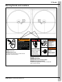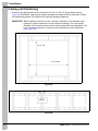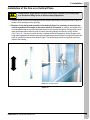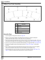
1
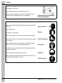
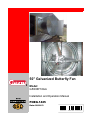
50" Galvanized Butterfly Fan
Model:
G50CBF16GA
Installation and Operation Manual
PNEG-1425
Date: 08-09-13
PNEG-1425
Congratulations
You have just purchased one of the best ventilation fans in the industry designed to give years
of high velocity airflow while saving hundreds of dollars in electrical usage. Please take some
time to read through this manual and familiarize yourself with the proper installation methods and
operation of the fan.
FEATURES
• 23500 CFM @ 24.0 CFM/W @ 0.05" S.P.
• One year warranty on parts
• Shutterless operation - No shutters to clean
• Consistent airflow through flock growout
• Easy assembly and maintenance
• On-site service and support
Unpacking
Before beginning installation, check the condition of the fan. Remove the overwrap and packing
materials and examine all parts and components for shipping damage. Any damage incurred
must be reported immediately to the freight carrier.
2
Model
: G50CBF16GA
Size
: 50" Galvanized Housing and Cone
Voltage
: 115V/230V
Amps
: 13.0/6.5
Frequency
: 50/60 Hz Single Phase
PNEG-1425 50" Galvanized Butterfly Fan
Table of Contents
Contents
Chapter 1 Safety .....................................................................................................................................................4
Safety Guidelines ...................................................................................................................................4
Safety Instructions ..................................................................................................................................5
General Safety Information ....................................................................................................................7
Chapter 2 Decals ....................................................................................................................................................9
Warning Decals and Locations ..............................................................................................................9
Chapter 3 Installation ..........................................................................................................................................10
Framing and Positioning ......................................................................................................................10
Installation of the Fan on a Vertical Plane ............................................................................................11
Tabbed Cone Panel Assembly .............................................................................................................12
Butterfly Assembly ...............................................................................................................................14
Grill Guard Assembly ...........................................................................................................................15
Inlet Grill Assembly ..............................................................................................................................15
Chapter 4 Wiring ..................................................................................................................................................17
Electrical Hook-Up ...............................................................................................................................17
Chapter 5 Operation ............................................................................................................................................18
Start-Up and Operation of the Butterfly Fan .........................................................................................18
Chapter 6 Troubleshooting .................................................................................................................................19
Troubleshooting Guide .........................................................................................................................19
Chapter 7 Parts List .............................................................................................................................................20
Chapter 8 Exploded Diagram ..............................................................................................................................22
Chapter 9 Warranty ..............................................................................................................................................25
PNEG-1425 50" Galvanized Butterfly Fan
3
1. Safety
Safety Guidelines
This manual contains information that is important for you, the owner/operator, to know and understand.
This information relates to protecting personal safety and preventing equipment problems. It is the
responsibility of the owner/operator to inform anyone operating or working in the area of this equipment
of these safety guidelines. To help you recognize this information, we use the symbols that are defined
below. Please read the manual and pay attention to these sections. Failure to read this manual and its
safety instructions is a misuse of the equipment and may lead to serious injury or death.
This is the safety alert symbol. It is used to alert you
to potential personal injury hazards. Obey all safety
messages that follow this symbol to avoid possible
injury or death.
DANGER
WARNING
4
DANGER indicates a hazardous situation which, if not
avoided, will result in death or serious injury.
WARNING indicates a hazardous situation which, if not
avoided, could result in death or serious injury.
CAUTION
CAUTION, used with the safety alert symbol, indicates a
hazardous situation which, if not avoided, could result in
minor or moderate injury.
NOTICE
NOTICE is used to address practices not related to
personal injury.
PNEG-1425 50" Galvanized Butterfly Fan
1. Safety
Safety Instructions
Our foremost concern is your safety and the safety of others associated with this equipment. We want to
keep you as a customer. This manual is to help you understand safe operating procedures and some
problems that may be encountered by the operator and other personnel.
As owner and/or operator, it is your responsibility to know what requirements, hazards, and precautions
exist, and to inform all personnel associated with the equipment or in the area. Safety precautions may be
required from the personnel. Avoid any alterations to the equipment. Such alterations may produce a very
dangerous situation where SERIOUS INJURY or DEATH may occur.
This equipment shall be installed in accordance with the current installation codes and applicable
regulations, which should be carefully followed in all cases. Authorities having jurisdiction should be
consulted before installations are made.
Install and Operate Electrical Equipment Properly
Electrical controls should be installed by a qualified electrician
and must meet the standards set by the National Electrical Code
and all local and state codes.
Disconnect and lock out all power sources before installing
wires/cables or servicing equipment.
Electric Shock Hazard
Keep Hands Away from Moving Parts
DO NOT put hand or arm in fan. Rotating parts can crush
and dismember.
DO NOT put any kind of tool inside fan to try and clear debris while
the fan is running. Damage to the equipment will result.
ALWAYS turn OFF and lock out all power sources before
servicing equipment.
Rotating Fan Blade
Lifting Hazard
Single person lift could cause injury.
Use two or more people or a mechanical lifting device to lift/move
heavy equipment.
Use Assistance When Lifting or
Moving Heavy Equipment
PNEG-1425 50" Galvanized Butterfly Fan
5
1. Safety
Prepare for Emergencies
Be prepared if fire starts.
Keep a first aid kit and fire extinguisher handy.
Keep emergency numbers for doctors, ambulance service,
hospital, and fire department near your telephone.
Keep Emergency Equipment
Quickly Accessible
Wear Protective Clothing
Wear close-fitting clothing and safety equipment appropriate
to the job.
Eye Protection
Remove all jewelry.
Tie long hair up and back.
Gloves
Wear safety glasses at all times to protect eyes from debris.
Wear gloves to protect your hands from sharp edges on plastic
or steel parts.
Wear steel-toed boots to help protect your feet from falling
debris. Tuck in any loose or dangling shoestrings.
Steel-Toed Boots
Respirator
A respirator may be needed to prevent breathing potentially
toxic fumes and dust.
Wear a hard hat to help protect your head.
Hard Hat
Wear appropriate fall protection equipment when working at
elevations greater than six feet (6').
Fall Protection
6
PNEG-1425 50" Galvanized Butterfly Fan
1. Safety
General Safety Information
Users Manual
This manual contains information and instructions essential to the safe installation and use of the
50" Galvanized Butterfly Fan. This manual should be read thoroughly before attempting any installation
or use of the fan. Keep this manual in a location that it can be readily accessed. Failure to read the manual
and its safety instructions constitutes misuse of the product.
Safety in Handling the Butterfly Fan
This unit should be installed and maintained by a qualified technician familiar with the use and
function of ventilation fans. This will prevent situations leading to damaged components and/or injury.
Whenever possible, use mechanical lifting equipment when lifting or moving the fan during installation.
Where manual handling is required, seek assistance from other people.
Correct Use of the Butterfly Fan
The fan is designed solely for the purpose of ventilating agricultural buildings. Use of the fan in any other
way is a misuse of the equipment and may endanger yours or another person’s safety and health.
In the installation and use of the Butterfly Fan only genuine Cumberland parts are to be used. Use of other
non-genuine parts is a misuse and may lead to dangerous situations.
This fan is not designed for use in atmospheres where the risk of explosion is foreseen. Such
environments may include enclosed areas of high dust concentrations, gas, vapors and fumes.
Use in such an environment is prohibited. If in doubt, contact Cumberland or your dealer.
Safety Guards
The Butterfly Fan contains moving and electrical parts which will cause serious injury, even death if
touched. Guards are placed on the fan to protect you. Operating the fan at any time with guards removed
or incorrectly fitted is a serious misuse of the fan and endangers you and others safety.
Safety in Maintenance
While the Butterfly Fan is designed to keep maintenance to a minimum, some items such as greasing the
bearings and belt replacement will be required over the life of the fan. Do not attempt any maintenance or
repairs on the fan unless you are competent to do so. Remember that the fan may, in certain situations,
operate under automatic control and will start without warning. Never attempt any work on the fan without
first isolating it from the power supply and locking out the isolator so that only you can turn the power back
ON. For your safety, follow the guidelines given in the maintenance section on Page 18 of this manual.
Before re-starting the fan, ensure that all electrical enclosures are locked, closed and all guards and other
safety measures are correctly fitted. If in doubt, contact your dealer or Cumberland for assistance.
PNEG-1425 50" Galvanized Butterfly Fan
7
1. Safety
Electrical Safety
Provisions for an adequate and safe power supply to the fan unit are essential to your safety. Cumberland
recommends that a competent and qualified electrician undertake all electrical wiring. All wiring is to be
installed in accordance with National, State, and Local electrical codes. Fans used to ventilate
livestock buildings and other rooms where continuous air movement is essential should be connected to
individual electrical circuits with a minimum of two (2) circuits per room.
We strongly recommend the installation of supplementary natural ventilation as well as a back-up
thermostat. There should also be an alarm system on at least one cooling stage. For connection
requirements, refer to the diagram on the motor nameplate and also to information enclosed with
the fan control used.
For single phase fans, motor overload protection should be provided for each fan. A circuit breaker or
slow blow motor type fuse must be used. A safety cut-off switch should be located adjacent to each fan.
Contact your local distributor for the correct cut-off switch.
The motor must be securely and adequately grounded. This can be accomplished by wiring with a
grounded conduit or a separate ground wire attached to the motor’s ground lug. Do not attempt operation
unless the motor is sufficiently grounded.
Do not kink power cable and never allow cable to come in contact with oil, grease, hot surfaces,
or chemicals.
Remember, electrical safety is your responsibility.
8
PNEG-1425 50" Galvanized Butterfly Fan
2. Decals
Warning Decals and Locations
WARNING
WARNING
STAY CLEAR OF
ROTATING BLADE
SHEAR POINT
Keep hands clear of moving
parts. Do not operate with
guard removed. Disconnect
and lockout power before
servicing.
DC-995
DC-995 - 2.0" x 4.5"
WARNING Shear Point
Located in lower right corner on both front and
back sides of the fan housing.
Blade may start
automatically.
May cause serious injury.
Disconnect and
lockout power sources
before servicing.
HIGH VOLTAGE.
Will cause serious
injury or death.
Lockout power
before servicing.
WARNING
FLYING OBJECTS
HAZARD.
Danger of eye injury.
Wear eye protection.
DC-1540
DC-1540 - 5.0" x 7.5"
DANGER High Voltage
WARNING Stay Clear of Rotating Blade
WARNING Flying Objects Hazard
Located in lower right corner on both front and back
sides of the fan housing.
PNEG-1425 50" Galvanized Butterfly Fan
9
3. Installation
Framing and Positioning
1. Construct the opening frame to the correct size (55-1/4" H x 55-1/4" W) as shown below in
Figure 3A. Remember, framing must be able to support the weight of the fan assembly. Ensure
the load bearing portion of the bottom sill is rigid and properly supported.
IMPORTANT: When installing more than one fan, maintain a minimum of 10" between rough
openings to ensure clearance of cones outside of buildings. The cone largest
diameter is 59" and allowances must be made to keep the cones separated. If not
sure of sufficient clearance, contact your local distributor for more information.
(See Figure 3B.)
55-1/4" Tall
55-1/4" Wide
Figure 3A
10"
Minimum
Figure 3B
10
PNEG-1425 50" Galvanized Butterfly Fan
3. Installation
Installation of the Fan on a Vertical Plane
CAUTION
Lifting Hazard. Single person lift could cause injury. Use two (2) or more people
or a mechanical lifting device to lift/move heavy equipment.
1. Position the fan in front of the opening from the inside of the building. Using a minimum of two (2)
people, lift fan housing into the opening.
2. Because of the design and operation of the butterfly flaps it is necessary to mount the fan
vertical regardless of the angle of the wall to which it is mounted. In order to accomplish this it
is recommended that a level be positioned vertical on the housing and shims (furring strips can be
used) be placed behind either the top or bottom mounting flanges until the fan is fully vertical.
(See Figure 3C.) Once you confirm the fan is setting vertical in the opening, fasten flanges to the
rough opening framework with the wood mounting screws provided. Failure to complete this step can
result in insufficient closure of the butterfly flaps. The fan housing should now be flush and level
inside of the framing.
NOTE: Fan must be vertical.
Figure 3C
PNEG-1425 50" Galvanized Butterfly Fan
11
3. Installation
Tabbed Cone Panel Assembly
Figure 3D
Ref #
Description
A
Top Panel
B
Side Panel
C
Bottom Panel
D
Drain Hole
E
Large Radius
Assembly Steps
1. Lay cone panels on the ground as shown in Figure 3D.
2. Slip four (4) cone panels together using tab and slot connections on edges of each panel.
(Please note that all tabs must be on the inside of the cone assembly.)
3. Place bolts through holes and thread nuts into place to hold four (4) cone panels together. (Nuts must
be located on the outside of the cone assembly.) (Do not tighten nuts.) (See Figure 3E on Page 13.)
4. Once four (4) cone panels are assembled stand assembly up on large radius side. (See Figure 3D.)
5. Pull both ends together create a heart shape as shown in Figure 3E on Page 13 to slide tabs
into slots.
6. Place remaining bolts through holes and thread remaining nuts into place to hold cone together.
(Nuts must be located on the outside of the cone assembly.) (Do not tighten nuts.)
7. Install assembled cone onto fan venturi unit using cone strut angles provided. (See Figure 3F on
Page 13.) (Make sure bottom panel with drain hole is closest to the ground.)
12
PNEG-1425 50" Galvanized Butterfly Fan
3. Installation
Nuts on outside of
cone assembly
Figure 3E
Cone strut angles
Figure 3F
PNEG-1425 50" Galvanized Butterfly Fan
13
3. Installation
Butterfly Assembly
1. Install the spring clips (12-0457) (2 pieces) as shown in Figure 3G onto the butterfly frame.
2. The V-shaped center bar of the butterfly frame weldment should be positioned vertically, with the
bottom lining up with the slots farthest out on the cone and the top lined up with the slots farthest in
on the cone. This will give the butterfly frame weldment a slight tilt back (~ 1"). This aids the closing
of the butterfly flaps.
3. Use 1/4" x 1-1/4" bolts and nuts to fasten the butterfly frame weldment to the panels. Tighten the
1/4" nuts. Attach the springs from the doors to the spring clip and push the flaps open and they should
close automatically from the spring tension, completely sealed by the magnets on the butterfly frame
weldment assembly. See Figure 3H for assembly inside of cone.
Spring clip
(12-0457)
Figure 3H Inside Cone
Figure 3G Spring Clip
14
PNEG-1425 50" Galvanized Butterfly Fan
3. Installation
Grill Guard Assembly
Position grill guard lining up attachment hoops with the holes in the cone panels at 3, 6, 9, 12 o’clock
positions. Attach and tighten using the 5/16" x 1" bolts and 5/16" whiz nuts. (See Figure 3I.)
Figure 3I
Inlet Grill Assembly
1. Remove the folded Inlet grill from the packaging. Unfold all four (4) sides lining them up perpendicular
to each other. Using the black wire ties, link the sides together using two (2) ties per corner.
(See Figure 3J.) After pulling them tight, clip off excess wire tie. (See Figure 3K.) Attach hanging
hooks in corners as shown in Figure 3L and Figure 3M on Page 16 (upper left and lower right shown).
Wire tie
Wire tie
Wire tie excess
Figure 3J Unclipped Wire Tie
PNEG-1425 50" Galvanized Butterfly Fan
Figure 3K Clipped Wire Tie
15
3. Installation
Figure 3L Inlet Grill Hanging Hook - Top
Figure 3M Inlet Grill Hanging Hook - Bottom
16
PNEG-1425 50" Galvanized Butterfly Fan
4. Wiring
Electrical Hook-Up
As previously mentioned, All wiring should be installed in accordance with National, State and Local
electrical codes. A certified electrician should complete this portion of the installation to ensure safety and
that the wiring is correct for the application.
1. First, remove the back cover of the motor exposing the wiring block. (See Figure 4A.)
Ground lug
Hole for conduit
Gusset for wire
(remove rubber plug)
Figure 4A
2. The motor is designed to use either a solid clamping conduit on the side of the motor or the supplied
wire with a three-prong plug attached. In either case, it is important to attach the ground wire to the
ground lug as depicted in Figure 4A. For correct motor rotation (CCW), the Red wire should be
located on the L2 connection as depicted. If this is not the case, switch the Red and Black wires.
Refer to wiring diagram on the side of the motor for correct wiring for 115V and 230V supply.
3. Fans used to ventilate livestock buildings or other rooms where continuous air movement is
essential should be connected to individual electrical circuits with a minimum of two (2) circuits per
room. For connection requirements, refer to diagram on the motor nameplate. For single phase
fans motor overload protection should be provided for each fan. A safety cut-off switch should
be located next to each fan. A circuit breaker switch or slow blow motor type fuses must be used.
(See Figure 4B.) 3 Phase fans require three (3) pole contactors with overload protection.
Information in paranthesis refers to 120 VAC.
L1 (Hot)
L1 (Hot)
T1 (Hot)
T1 (Hot)
120 VAC or
240 VAC Power L2 (Neu)
L2 (Neu)
T2 (Neu)
T2 (Neu)
G
G
Motor overload protection showing disconnect single phase.
Figure 4B
PNEG-1425 50" Galvanized Butterfly Fan
17
5. Operation
Start-Up and Operation of the Butterfly Fan
Disconnect and lock out all power sources before servicing equipment.
DANGER
1. With the fan de-energized, rotate the prop by turning the fan pulley, look for clearance between
the prop tip and the housing. Replace all guards and check all fasteners to ensure they are tight.
When satisfied, energize the fan and make note of direction of rotation. The prop should turn
counterclockwise when viewed from inside the house and the butterfly flaps should open completely.
They are designed to stay open during fan operation and close when the fan is de-energized. If the
prop is turning backwards, the flaps will not open. If this is the case, refer to Figure 3J on Page 15
and switch the black and red wires as noted after de-energizing the fan. Re-check the operation and
when satisfied the fan is operating properly, follow the instructions below.
2. Write down the date that the Butterfly Fan went into service and follow the maintenance schedule
as listed below:
a. Check the belt, pulleys and the bearings after every two (2) months of service. The belt tensioner
should be positioned between the 2nd and 3rd notch as indicated by the mark on the body of the
tensioner. Under tensioning will result in belt slippage, over tensioning will lead to premature belt
and bearing failure.
b. The motor and shaft bearings are lubricated at the factory. The motor bearings should never
require lubrication over the life of the fan but the fan shaft bearings should be greased after every
2-3 months of use, using the zerks on top of the pillow blocks. Only use a small amount of lithium
soap base grease after cleaning the zerks. Contact your fan distributor for the proper grease.
3. When cleaning the fans, Do Not Spray bearings, tensioner or motor directly with a pressure washer
as this Will lead to premature failure of these components. After cleaning the fan, simply wipe these
parts with a clean rag to remove dirt and debris. Failure to follow these instructions will void the
warranty on these components.
18
PNEG-1425 50" Galvanized Butterfly Fan
6. Troubleshooting
Troubleshooting Guide
Fan would not Start
1. Check the power supplied to the fan at the point closest to the fan.
2. Check the wiring to the fan.
3. Override the controller (set to manual) and re-check.
4. Contact your Cumberland distributor.
Fan Turns Slow
1. Check the voltage supplied (must be within ± 10% if the nominal voltage).
2. De-energize the power and check the wiring at the rear of the motor.
3. De-energize the power, remove the belt and rotate both the motor and fan pulleys. Do they turn
freely? If not, contact your Cumberland distributor.
Fan is Noisy or Vibrates
1. De-energize the fan. Check for loose parts, i.e., bolts, screws, motor, pulleys, prop. Are the fan blades
even? Turn the prop inside of the venturi and look at the blade tips as they move past the same
location. Do they all three appear even? (NOTE: They can be a little different without any problems.)
If they are significantly different contact your Cumberland distributor for more information.
2. Is the noise coming from the bearings? Lubricate per instructions and energize the fan. Did the noise
subside? If not, the bearings are probably damaged and in need of replacement.
Butterfly Flaps do not Close Completely
1. Check vertical alignment of the butterfly frame using a level. If not level, shim the housing out as
described on Page 11.
2. Check the springs, are they attached? If not, re-attach. Are they stretched and no longer under
tension? Contact your Cumberland distributor for replacements.
3. Check the butterfly flap bushings, are they full of contamination? Rinse with water and remove all
buildup of dirt and contamination. Move the flap by hand until loose and moving freely.
4. Look to see if the flap is bent. With the fan OFF completely close both flaps and look along mating
surface of the butterfly frame. Are all points contacting? If not, bend the flap slightly until all
surfaces contact.
PNEG-1425 50" Galvanized Butterfly Fan
19
7. Parts List
No.
20
Part #
Description
Qty
U/M
EA
1
10-0200
Galvanized Cone Mounting Hardware
1
2
12-0312
50" Galvanized Butterfly Cone Bracket
4
3
S-10268
Flange Nut 5/16"-18 JS Grade 5
32
4
S-6606
Flange Bolt 5/16"-18 x 3/4" ZN Grade 5
32
5
10-0103
Cord/Terminal Bag - Galvanized Fans
1
6
10-0102
Terminal Bag - Galvanized Fans
1
7
S-7145
Cord, 96"-16/3 SJT w/ Male
1
8
10-0106
50" Galvanized Butterfly Fan Install Kit
1
9
CW-2002
Hook 3/16" x 1-1/2" Lagged Thread
4
10
S-6997
Bolt, HHCS 1/4"-20 x 1-1/4" ZN Grade 5
4
11
S-7215
Flange Nut 1/4"-20 Zinc
5
12
S-9248
Screw, WS 1/4"-10 x 1-1/2" FHP ZN
16
13
12-0457
Clip, Spring Mounting (Butterfly Fans)
2
14
S-6998
Bolt, HHCS 1/4"-20 x 1" ZN Grade 5
1
15
12-0486
50" Galvanized Butterfly Sub-Assembly
1
16
12-0487-GY
Butterfly Frame Weldment 53" Painted Grey
1
17
12-0464
Block, Nylon Mounting
2
18
12-0319
Washer, Nylon
4
19
12-0492
Butterfly Flap 50" Galvanized Fan
2
20
S-1101
Bolt, HHCS 1/4"-20 x 1/2" ZN
2
21
S-853
Bolt, HHCS 1/4"-20 x 1-1/2" ZN
4
22
12-0405
Galvanized Flap Shaft 50" Butterfly
2
23
16-0092
Disk Magnet 1/2" Diameter 1/8" Thick
4
24
S-10264
Tape Foam Seal 1/2" x 14'
25
16-0100
Spring, SS 8.70" Long - Butterfly Flap
2
26
S-9440
Rivet, POE 1/8" Diameter
4
27
S-1429
Bolt, HHCS 1/4"-20 x 3/4" ZN Grade 2
2
28
S-3229
Bolt, HHCS 1/4"-20 x 1-3/4" ZN Grade 2
2
29
S-7025
Nylock Nut 1/4"-20 ZN Hex Grade 5
4
30
S-7215
Flange Nut 1/4"-20 Zinc
4
31
11-0494
Conefan Bearing Plate Strut
1
32
11-0495
Bearing Plate, Galvanized Fan, Tensioner
1
33
11-0333
Front Inlet Grill 50" Short Fan
1
34
11-0334
Side Inlet Grill 50" Short Fan
4
EA
EA
EA
14'
PNEG-1425 50" Galvanized Butterfly Fan
7. Parts List
No.
Part #
Description
Qty
35
S-9351
Clip 7/8" x 43/64" HRCLP 34G
20
36
11-0342-WH
Guard, 59" 50" Short Fan Paint
1
37
12-0274
Venturi, 50" Butterfly Metal (50-1/2" I.D.)
1
38
12-0481
Top Panel 50" Galvanized Fan
1
39
12-0482
Bottom Panel 50" Galvanized Fan
1
40
12-0483
Left Panel 50" Galvanized Fan
1
41
12-0484
Right Panel 50" Galvanized Fan
1
42
12-0306
50" Galvanized Butterfly Cone Panel
3
43
12-0311
50" Galvanized Butterfly Bottom Cone Panel
1
44
13-0103RS
Propeller, 50" Galvanized (Solid Rivet)
1
45
15-0126
Motor 1.5 HP, 1 PH, 1725 RPM 50/60 Hz
1
46
16-0007
Pulley AL104 x 1" MXB Fans
1
47
16-0016
Sheave 1 Groove 3.45" Diameter x 5/8" Bore
1
48
16-0076
Bearing 1" Pillow Block AVS FA
2
49
16-0087
1" Shaft - Dual Key - Tensioner
1
50
16-0088
A-46 V-Belt, 48" Nominal Length
1
51
91-0057
Rotary Tensioner Assembly w/ Splash Guards
1
52
DC-1540
Decal, Danger/Warning
2
53
DC-1571
Decal Grease Instructions All BD Fans
1
54
DC-983
Decal, AVS Logo 10-1/2" x 2"
2
55
DC-995
Decal, Warning Shear Point
2
56
S-1054
Split Lock Washer 3/8" ZN
1
57
S-248
Flat Washer 3/8" USS ZN YDP Grade 2
4
58
S-10268
Flange Nut 5/16"-18 JS Grade 5
13
59
S-4336
Screw, MS 5/16"-18 x 1" THS ZN Grade 2
4
60
S-6606
Flange Bolt 5/16"-18 x 3/4" ZN Grade 5
13
61
S-7383
Nylock Nut 3/8"-16 ZN Grade 5
4
62
S-7419
Screw, SDS #10-16 x 1-1/4" HWH SS
6
63
S-8978
Screw, TCSF #10-32 x 1/2" HWH ZN
40
64
S-9168
Square Key 1/4" x 1"
2
65
S-9303
Flange Bolt 3/8"-16 x 1-1/2" YDP Grade 8
5
66
PNEG-1425
50" Galvanized Butterfly Fan Instruction Manual
1
PNEG-1425 50" Galvanized Butterfly Fan
U/M
21
8. Exploded Diagram
6
14
7
13
15
20
8
5
19
12
4
11
18
1
10
9
17
16
3
2
22
PNEG-1425 50" Galvanized Butterfly Fan
8. Exploded Diagram
Exploded Diagram
Ref #
Part #
Description
Qty
1
11-0333
Inlet Grill
1
2
12-0482
Bottom Panel
1
3
12-0484
Right Panel
1
4
12-0487-GY
Butterfly Frame
1
5
12-0483
Left Panel
1
6
12-0481
Top Panel
1
12-0306
50" Galvanized Butterfly Cone Panel
3
12-0311
50" Galvanized Butterfly Bottom Cone Panel
1
12-0492
Butterfly Flap 50" Galvanized Fan
2
7
8
9
11-0494
Bearing Plate Strut
1
10
16-0007
Pulley AL104
1
11
16-0016
Sheave 1 Groove 3.45 Diameter
1
12
15-0126
Motor 1.5 HP, 1 PH/60 Hz
1
13
12-0274
Venturi 50"
1
14
12-0464
Block, Nylon Mounting
2
15
16-0087
1" Shaft/Dual Key
1
16
16-0076
Bearing 1" Pillow Block
2
17
11-0495
Bearing Plate 50" Fan
1
18
91-0045
Rotary Tensioner
1
19
12-0312
50" Galvanized Butterfly Cone Bracket
4
20
12-0405
Galvanized Flap Shaft 50" Butterfly
1
Exploded Diagram for XG50CBF356A
Ref #
Part #
Description
Qty
1
11-0333
Inlet Grill
1
2
12-0482
Bottom Panel
1
3
12-0484
Right Panel
1
4
12-0487-GY
Butterfly Frame
1
5
12-0483
Left Panel
1
6
12-0481
Top Panel
1
12-0306
50" Galvanized Butterfly Cone Panel
3
7
12-0311
50" Galvanized Butterfly Bottom Cone Panel
1
8
12-0492
Butterfly Flap 50" Galvanized Fan
2
9
11-0494
Bearing Plate Strut
1
10
16-0015
Sheave, AL 94 - 8.875" O.D. x 1" I.D. with Keyway
1
11
16-0050
Drive Sheave, 36" Fans - AK 39 x 5/8"
1
12
15-0138
Motor 1.75 HP 3 PH 115/230V 60 Hz 15/7.5 A
1
13
12-0274
Venturi 50"
1
14
12-0464
Block, Nylon Mounting
2
15
16-0087
1" Shaft/Dual Key
1
16
16-0076
Bearing 1" Pillow Block
2
17
11-0495
Bearing Plate 50" Fan
1
18
91-0045
Rotary Tensioner
1
19
12-0312
50" Galvanized Butterfly Cone Bracket
4
20
12-0405
Galvanized Flap Shaft 50" Butterfly
1
PNEG-1425 50" Galvanized Butterfly Fan
23
NOTES
24
PNEG-1425 50" Galvanized Butterfly Fan
9. Warranty
GSI Group, LLC Limited Warranty
The GSI Group, LLC (“GSI”) warrants products which it manufactures to be free of defects in materials and workmanship
under normal usage and conditions for a period of 12 months after sale to the original end-user or if a foreign sale,
14 months from arrival at port of discharge, whichever is earlier. The end-user’s sole remedy (and GSI’s only obligation)
is to repair or replace, at GSI’s option and expense, products that in GSI’s judgment, contain a material defect in materials
or workmanship. Expenses incurred by or on behalf of the end-user without prior written authorization from the GSI
Warranty Group shall be the sole responsibility of the end-user.
Warranty Extensions:
The Limited Warranty period is extended for the following products:
Product
Warranty Period
Performer Series Direct Drive Fan Motor
3 Years
* Warranty prorated from list price:
All Fiberglass Housings
Lifetime
0 to 3 years - no cost to end-user
All Fiberglass Propellers
Lifetime
3 to 5 years - end-user pays 25%
Feeder System Pan Assemblies
5 Years **
Feed Tubes (1-3/4" and 2.00")
10 Years *
** Warranty prorated from list price:
Centerless Augers
10 Years *
0 to 3 years - no cost to end-user
Watering Nipples
10 Years *
3 to 5 years - end-user pays 50%
Grain Systems
Grain Bin Structural Design
5 Years
Grain Systems
Farm Fans
Zimmerman
Portable and Tower Dryers
2 Years
Portable and Tower Dryer Frames and
Internal Infrastructure †
5 Years
AP Fans and Flooring
Cumberland
Feeding/Watering
Systems
5 to 7 years - end-user pays 50%
7 to 10 years - end-user pays 75%
† Motors, burner components
and moving parts not included.
Portable dryer screens included.
Tower dryer screens not included.
GSI further warrants that the portable and tower dryer frame and basket, excluding all auger and auger drive components,
shall be free from defects in materials for a period of time beginning on the twelfth (12th) month from the date of purchase
and continuing until the sixtieth (60th) month from the date of purchase (extended warranty period). During the extended
warranty period, GSI will replace the frame or basket components that prove to be defective under normal conditions
of use without charge, excluding the labor, transportation, and/or shipping costs incurred in the performance of this
extended warranty.
Conditions and Limitations:
THERE ARE NO WARRANTIES THAT EXTEND BEYOND THE LIMITED WARRANTY DESCRIPTION SET FORTH
ABOVE. SPECIFICALLY, GSI MAKES NO FURTHER WARRANTY OF ANY KIND, EXPRESS OR IMPLIED,
INCLUDING, WITHOUT LIMITATION, WARRANTIES OF MERCHANTABILITY OR FITNESS FOR A PARTICULAR
PURPOSE OR USE IN CONNECTION WITH: (I) PRODUCT MANUFACTURED OR SOLD BY GSI OR (II) ANY ADVICE,
INSTRUCTION, RECOMMENDATION OR SUGGESTION PROVIDED BY AN AGENT, REPRESENTATIVE OR
EMPLOYEE OF GSI REGARDING OR RELATED TO THE CONFIGURATION, INSTALLATION, LAYOUT, SUITABILITY
FOR A PARTICULAR PURPOSE, OR DESIGN OF SUCH PRODUCTS.
GSI shall not be liable for any direct, indirect, incidental or consequential damages, including, without limitation, loss of
anticipated profits or benefits. The sole and exclusive remedy is set forth in the Limited Warranty, which shall not exceed
the amount paid for the product purchased. This warranty is not transferable and applies only to the original end-user. GSI
shall have no obligation or responsibility for any representations or warranties made by or on behalf of any dealer, agent
or distributor.
GSI assumes no responsibility for claims resulting from construction defects or unauthorized modifications to products
which it manufactured. Modifications to products not specifically delineated in the manual accompanying the equipment at
initial sale will void the Limited Warranty.
This Limited Warranty shall not extend to products or parts which have been damaged by negligent use, misuse, alteration,
accident or which have been improperly/inadequately maintained. This Limited Warranty extends solely to products
manufactured by GSI.
Prior to installation, the end-user has the responsibility to comply with federal, state and local codes which apply to the
location and installation of products manufactured or sold by GSI.
9101239_1_CR_rev7.DOC
PNEG-1425 50" Galvanized Butterfly Fan
(revised July 2009)
25
This equipment shall be installed in accordance with
the current installation codes and applicable
regulations, which should be carefully followed in all
cases. Authorities having jurisdiction should be
consulted before installations are made.
1004 E. Illinois St.
Assumption, IL 62510-0020
Phone: 1-217-226-4421
Fax: 1-217-226-4420
www.gsiag.com
Cumberland is a part of GSI, a worldwide brand of AGCO.
Copyright © 2013 by
Printed in the USA
Group
CN-307813