1
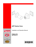
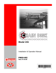
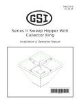
APP Series Knockdown Fan
Installation, Assembly and Operation Manual
PNEG-1016
Date: 04-21-15
PNEG-1016
APP Series Knockdown Fan is manufactured, assembled and packaged with the highest standard of
quality assurance. Please inspect and notify the factory in the unlikely event you discover defects in
workmanship. We appreciate hearing from you and will correct immediately.
Read carefully before attempting to assemble, install, operate or maintain the product described. Protect
yourself and others by observing all safety information. Use only genuine AP parts in the installation of
fans, use of non-genuine parts or failure to comply with instructions could result in personal injury and/or
property damage. This fan is not designed for use in atmospheres where risk of explosion is foreseen.
Such environments may include enclosed areas of high dust concentrations, gas vapors and fumes.
Use in such an atmosphere is prohibited. If in doubt, contact AP or your dealer.
Retain instructions for future reference.
Fan Models
CFM at 0.00 SP
Weight Lbs./kgs
Cubic Ft./mtrs
APPB-36*
11113
135 Lbs./61.20 kgs
34.5 Ft./0.97 mtrs
APPB-36C*
12290
170 Lbs./77.10 kgs
55.7 Ft./1.58 mtrs
APPB-50*
20856
214 Lbs./97.00 kgs
65 Ft./1.85 mtrs
APPB-50C*
23894
265 Lbs./120.20 kgs
65 Ft./1.85 mtrs
* Add - BLK suffix to end of fan model number for black fans.
For guidance or assistance on any issues relating to the safe use of your APP Fan contact AP.
Our address is:
Automated Production
1004 E. Illinois St.
Assumption, IL. 62510
Phone: 1-217-226-4421
2
PNEG-1016 APP Series Knockdown Fan
Table of Contents
Contents
Chapter 1 Safety .....................................................................................................................................................4
Cautionary Symbols Definitions .............................................................................................................4
Safety Instructions ..................................................................................................................................5
General Safety Information ....................................................................................................................6
Chapter 2 Decals ....................................................................................................................................................7
Safety Signs and Warnings ....................................................................................................................7
Chapter 3 Installation ............................................................................................................................................9
Chapter 4 Operation ............................................................................................................................................10
Chapter 5 Maintenance ........................................................................................................................................11
Cleaning ...............................................................................................................................................11
Lubrication ............................................................................................................................................11
Chapter 6 Wiring ..................................................................................................................................................12
Electrical Wiring ...................................................................................................................................12
Belt Drive Wirings for Single Phase Motors .........................................................................................13
Chapter 7 Dimension Chart .................................................................................................................................14
Chapter 8 AP Belt Drive Fan Assembly Instructions ........................................................................................15
Assembling the Motor Mount Leg and Bearing Plate ...........................................................................15
Installing the Motor and Bearing Support Assembly into the Fan Housing ..........................................16
Assembling the Motor ..........................................................................................................................18
Installing the Motor ...............................................................................................................................20
Aligning the Tensioner Arm ..................................................................................................................21
Installing the Bearings ..........................................................................................................................21
Installing the Driven Pulley onto the Shaft ...........................................................................................23
Installing the Propellar ..........................................................................................................................24
Installing the Belt ..................................................................................................................................25
Chapter 9 Installing a Discharge Cone ..............................................................................................................26
Assembling a Segmented Discharge Cone .........................................................................................27
Mounting the Cone to the Fan Housing ...............................................................................................28
Guard Detail for 50" Fan ......................................................................................................................29
Chapter 10 Parts List ...........................................................................................................................................30
Chapter 11 Warranty ............................................................................................................................................31
PNEG-1016 APP Series Knockdown Fan
3
1. Safety
Cautionary Symbols Definitions
Cautionary symbols appear in this manual and on product decals. The symbols alert the user of potential
safety hazards, prohibited activities and mandatory actions. To help you recognize this information, we
use the symbols that are defined below.
DANGER
This symbol indicates an imminently hazardous situation
which, if not avoided, will result in serious injury or death.
WARNING
This symbol indicates a potentially hazardous situation
which, if not avoided, may result in serious injury or death.
CAUTION
This symbol indicates a potentially hazardous situation which,
if not avoided, may result in minor or moderate injury.
CAUTION
This symbol indicates a potentially hazardous situation which,
if not avoided, may result in property damage.
This symbol indicates a general hazard.
This symbol indicates a prohibited activity.
This symbol indicates a mandatory action.
4
PNEG-1016 APP Series Knockdown Fan
1. Safety
Safety Instructions
Our foremost concern is your safety and the safety of others associated with this equipment. We want to
keep you as a customer. This manual is to help you understand safe operating procedures and some
problems that may be encountered by the operator and other personnel.
As owner and/or operator, it is your responsibility to know what requirements, hazards, and precautions
exist, and to inform all personnel associated with the equipment or in the area. Safety precautions may be
required from the personnel. Avoid any alterations to the equipment. Such alterations may produce a very
dangerous situation where SERIOUS INJURY or DEATH may occur.
This equipment shall be installed in accordance with the current installation codes and applicable
regulations, which should be carefully followed in all cases. Authorities having jurisdiction should be
consulted before installations are made.
Follow Safety Instructions
•
Carefully read and follow all safety messages in this
manual and safety signs on your machine. Keep signs
in good condition. Replace missing or damaged safety
signs. Replacement safety signs are available from
the manufacturer.
•
Learn how to operate the machine correctly. Do not
operate without instruction.
•
If you do not understand any part of this manual or
need assistance, contact your dealer.
User Manual
This manual contains information and instructions essential to the safe installation and use of the
APP Series Knockdown Fans. Read this manual thoroughly before attempting any installation or use of
the APP Fan. Keep this manual with the APP Fan or in a location where it can be readily accessed. Failure
to read this manual and its safety instructions is a misuse of the equipment.
Correct Use of the APP Series Knockdown Fan
The APP Series Knockdown Fan is designed solely for the purpose of ventilating agricultural buildings.
Use of the system in any other way is a misuse of the system and may endanger safety and health.
Only genuine AP parts are to be used in the installation and use of the APP Series Knockdown Fan.
Use of other non-genuine parts is a misuse of the system and may lead to dangerous situations imperilling
the safety and health of you and others.
This machine is not designed for use in atmospheres where there is a risk of explosion. Such
environments may include enclosed areas of high dusts concentrations, gas vapors and fumes. Use of the
APP Fan in such an environment is prohibited. If in doubt, contact AP or your dealer.
PNEG-1016 APP Series Knockdown Fan
5
1. Safety
Unpacking
When receiving the unit, inspect carefully for any damage that may have occurred during transit. Shipping
damage claim must be filed with carrier.
Electrical Safety
An adequate and safe power supply to the APP Series Knockdown Fan unit is essential for safety.
A competent and qualified electrician must undertake all electrical wiring. All wiring is to be installed
according to the National Standards and Regulations relevant to your Country and Region.
Safety Guards
The APP Series Knockdown Fan contains many moving and electrical parts, which will cause serious
injury or death if touched. Guards are placed on the machine for your protection. Operating the
machine at any time with guards removed or incorrectly fitted is a serious misuse of the machine and
endangers safety.
Safety in Handling the APP Series Knockdown Fan
Manual handling of the fans can be a cause of serious injury. Wherever possible, use mechanical lifting
equipment when lifting or moving fans during installation. Where manual handling is required, seek
assistance from other people.
To prevent injury, use suitable hand protection.
Safety in Maintenance
While the APP Series Knockdown Fan is designed to keep maintenance to a minimum, some repairs will
be necessary in the course of the life of the machine. Do not attempt any repairs on the machine unless
you are competent to do so. Remember that the APP Series Knockdown Fan may in cases operate under
automatic control and start without warning. Never attempt any work on the APP Series Knockdown Fan
without first isolating the machine from the main power and locking the isolator so that only you can turn
the power back ON.
Follow all the guidelines given in the maintenance section on Page 11 of this manual.
Before restarting the APP Series Knockdown Fan, ensure that all electrical enclosures are locked closed
and all guards and other safety measures are correctly fitted.
If in any doubt, contact your dealer or AP for assistance.
General Safety Information
This unit should be assembled and installed by a qualified technician.
Follow all local electrical and safety codes, as well as the National Electrical Code (NEC) and the
Occupational Safety and Health Act (OSHA).
Motor must be securely and adequately grounded. This can be accomplished by wiring with a grounded,
metal-clad raceway system by using a separate ground wire connected to the motor’s ground lug or other
suitable means.
Protect power cable from coming in contact with sharp objects.
Do not kink power cable and never allow cable to come in contact with oil, grease, hot surfaces,
or chemicals.
Make certain that the power source conforms to requirements of the equipment.
6
PNEG-1016 APP Series Knockdown Fan
2. Decals
Safety Signs and Warnings
The following pages show you exactly where the safety signs and warnings (decals) should be placed on
your APP Series Knockdown Fan. If a decal is missing, damaged or unreadable, please contact your
dealer or AP for a free replacement.
WARNING
SHEAR POINT
DANGER
Keep hands clear of moving
parts. Do not operate with
guard removed. Disconnect
and lockout power before
servicing.
WARNING
STAY CLEAR OF
ROTATING BLADE
Blade may start
automatically.
May cause serious injury.
GSI Group Inc. 217-226-4421
DC-995
Disconnect and
lockout power sources
before servicing.
WARNING
HIGH VOLTAGE
Will cause serious
injury or death.
Lockout power
before servicing.
WARNING
FLYING OBJECTS
HAZARD
Danger of eye injury.
Wear eye protection.
The GSI Group 217-226-4421
DC-1540
DC-1018
DANGER
WARNING
STAY CLEAR OF
ROTATING BLADE
Blade may start
automatically.
May cause serious injury.
Disconnect and
lockout power sources
before servicing.
DANGER
WARNING
STAY CLEAR OF
ROTATING BLADE
Blade may start
automatically.
May cause serious injury.
Disconnect and
lockout power sources
before servicing.
HIGH VOLTAGE
WARNING
HIGH VOLTAGE
Will cause serious
injury or death.
Lockout power
before servicing.
Will cause serious
injury or death.
Lockout power
before servicing.
The GSI Group 217-226-4421
WARNING
FLYING OBJECTS
HAZARD
Danger of eye injury.
Wear eye protection.
DC-1540
FLYING OBJECTS
HAZARD
The GSI Group 217-226-4421
Danger of eye injury.
Wear eye protection.
DC-1540
Inside housing
PNEG-1016 APP Series Knockdown Fan
7
2. Decals
DANGER
WARNING
STAY CLEAR OF
ROTATING BLADE
Blade may start
automatically.
May cause serious injury.
Disconnect and
lockout power sources
before servicing.
DANGER
WARNING
STAY CLEAR OF
ROTATING BLADE
Blade may start
automatically.
May cause serious injury.
Disconnect and
lockout power sources
before servicing.
HIGH VOLTAGE
Will cause serious
injury or death.
Lockout power
before servicing.
The GSI Group 217-226-4421
WARNING
HIGH VOLTAGE
WARNING
FLYING OBJECTS
HAZARD
Will cause serious
injury or death.
Lockout power
before servicing.
Danger of eye injury.
Wear eye protection.
The GSI Group 217-226-4421
DC-1540
FLYING OBJECTS
HAZARD
Danger of eye injury.
Wear eye protection.
DC-1540
Left side
DANGER
WARNING
STAY CLEAR OF
ROTATING BLADE
Blade may start
automatically.
May cause serious injury.
Disconnect and
lockout power sources
before servicing.
DANGER
WARNING
STAY CLEAR OF
ROTATING BLADE
Blade may start
automatically.
May cause serious injury.
Disconnect and
lockout power sources
before servicing.
HIGH VOLTAGE
Will cause serious
injury or death.
Lockout power
before servicing.
HIGH VOLTAGE
Will cause serious
injury or death.
Lockout power
before servicing.
The GSI Group 217-226-4421
The GSI Group 217-226-4421
WARNING
WARNING
FLYING OBJECTS
HAZARD
Danger of eye injury.
Wear eye protection.
DC-1540
FLYING OBJECTS
HAZARD
Danger of eye injury.
Wear eye protection.
DC-1540
Right side
DANGER
WARNING
STAY CLEAR OF
ROTATING BLADE
Blade may start
automatically.
May cause serious injury.
Disconnect and
lockout power sources
before servicing.
DANGER
WARNING
STAY CLEAR OF
ROTATING BLADE
Blade may start
automatically.
May cause serious injury.
HIGH VOLTAGE
Will cause serious
injury or death.
Lockout power
before servicing.
The GSI Group 217-226-4421
WARNING
FLYING OBJECTS
HAZARD
Disconnect and
lockout power sources
before servicing.
HIGH VOLTAGE
Will cause serious
injury or death.
Lockout power
before servicing.
The GSI Group
217-226-4421
WARNING
FLYING OBJECTS
HAZARD
Danger of eye injury.
Wear eye protection.
DC-1540
Danger of eye injury.
Wear eye protection.
DC-1540
Motor mount plate
8
PNEG-1016 APP Series Knockdown Fan
3. Installation
Fans should be installed in an exterior wall located where there will be no obstructions to the flow of air
into or out of the fan.
Once a location has been determined, an opening should be made in the wall and framed to provide
enough clearance around the fan housing. (See rough opening chart on Page 10.)
Framing must be able to support the weight of the fan assembly.
Manual handling of the fans may result in serious injury. Where appropriate, use mechanical methods of
lifting during installation. Where manual handling is required, ensure you have adequate assistance.
Position fan assembly in the framed opening. Rigidly mount the housing side flanges to the framework
using mounting screws.
Remove electrical cover and connect power leads to motor terminals, using approved wiring method.
It is recommended to use the watertight connector included with the motor, if it is possible in the
application. (Motor terminal connection data is provided on motor nameplate and in this manual.) Use
adequate size wire for all branch and feeder runs. When speed control is used, follow the installation
procedures recommended by the speed control manufacturer.
Re-install electrical cover.
Unit is now ready for operation.
PNEG-1016 APP Series Knockdown Fan
9
4. Operation
Fan Model
Width (in.)
Inside Height (in.)
Outside Height (in.)
B
A
APPB-36*
44-1/2
44-1/2
43-1/2
APPB-50*
56
56
55
* Add - BLK suffix to end of fan model for black fans.
Figure 4A
Ref #
Description
A
Outside House Height
B
Inside House Height
Units may be operated using a switch, thermostat, timer or controller.
Follow wiring and operation instructions furnished with the control system selected.
When using speed controllers, follow the operation procedures recommended by the
controller manufacturer.
1. Set thermostat setting to a desired temperature. Fan will operate only when ambient temperature is
above the thermostat set temperature.
2. Some controllers have idle speed controls. Set idle speed such that the blade RPM is within the
RPM range listed in the performance table.
10
PNEG-1016 APP Series Knockdown Fan
5. Maintenance
Cleaning
Clean the blade and shutter at regular intervals. Dirt and debris can cause the fan blade to become
unbalanced, resulting in excessive vibration and poor performance.
Lubrication
Motor is pre-lubricated at the factory and will not require any further lubrication.
PNEG-1016 APP Series Knockdown Fan
11
6. Wiring
Electrical Wiring
All wiring should be installed in accordance with National, State and Local Electrical Codes. Fans used to
ventilate livestock buildings or other rooms where continuous air movement is essential should be
connected to individual electrical circuits, with a minimum of two (2) circuits per room. We strongly
recommend the installation of supplementary natural ventilation as well as a back-up thermostat and an
alarm system on at least one cooling stage.
For electrical connection requirements, refer to Figure 6A on motor nameplate and to information enclosed
with the “AVS” fan control to be used.
Figure 6A
12
PNEG-1016 APP Series Knockdown Fan
6. Wiring
Belt Drive Wirings for Single Phase Motors
Figure 6B
Motor overload protection should be provided for each fan. A circuit breaker switch or slow blow motor
type fuses must be used.
NOTE: A safety cut-off switch should be located adjacent to each fan, such as “AP” #’s:
E100-A1063 - 2-1/2 Amp
E100-A1064 - 5.0 Amp
E100-A1065 - 8.0 Amp
E100-A1066 - 15.0 Amp
Figure 6C
Back-up thermostats such as the TH-1, should always be used in conjunction with the control system.
These should be placed on a separate circuit to give the animals ventilation in the event that the
controller fails.
PNEG-1016 APP Series Knockdown Fan
13
7. Dimension Chart
Side view
Front view
Figure 7A
Fan Model
“A”
“B”
“C”
APP-36F/APPB-36F*
30-1/4"
N/A
37-7/8"
APP-36FC/APPB-36FC*
54-1/2"
27"
44-3/8"
APPB-50*
34-1/4"
N/A
50-3/8"
APPB-50C*
55"
24"
56-3/8"
* Add - BLK suffix to end of fan model for black fans.
Ref #
14
Description
D
Airflow
E
Slope
PNEG-1016 APP Series Knockdown Fan
8. AP Belt Drive Fan Assembly Instructions
Assembling the Motor Mount Leg and Bearing Plate
1. Align the motor mount leg (A) to the center of the bearing plate (B). (See Figure 8A.)
2. Fasten them together using bolts (C) and nuts (D) and torque to 120 ft.-lbs.
3. Install the grommet (E) into the bearing plate on the side where the power will be installed.
(See Figure 8B.)
4. Loosely install the belt tensioner (F) to the flange of the bearing plate on the side where the power
will be installed. (See Figure 8C on Page 16.)
A
D
C
B
Figure 8A
E
Figure 8B
PNEG-1016 APP Series Knockdown Fan
15
8. AP Belt Drive Fan Assembly Instructions
Assembling the Motor Mount Leg and Bearing Plate (Continued)
Ref #
F
Description
A
Motor Mount Leg
B
Bearing Plate
C
Bolt
D
Nut
E
Grommet
F
Belt Tensioner
Figure 8C
Installing the Motor and Bearing Support Assembly into the
Fan Housing
1. Align the motor mount leg (A) with the bottom holes in the fan housing.
2. Align the bearing plate (B) with the holes in the sides of the fan housing. (See Figure 8D.)
3. Fasten the supports (A and B) to the fan housing (C) using bolts (D), washers (E) and nuts (F).
(See Figure 8E and Figure 8F on Page 17.)
B
A
Figure 8D
16
PNEG-1016 APP Series Knockdown Fan
8. AP Belt Drive Fan Assembly Instructions
Installing the Motor and Bearing Support Assembly into the
Fan Housing (Continued)
D
E
F
C
Figure 8E
D
E
F
Figure 8F
Ref #
Description
A
Motor Mount Leg
B
Bearing Plate
C
Fan Housing
D
Bolt
E
Washer
F
Nut
PNEG-1016 APP Series Knockdown Fan
17
8. AP Belt Drive Fan Assembly Instructions
Assembling the Motor
1. Use generous amount of Loctite 242® (A) around the inside of the pulley bore (B). (See Figure 8G
and Figure 8H.)
A
A
B
Figure 8H
Figure 8G
2. Place the key (C) into the keyway on the motor shaft (D). (See Figure 8I.)
C
D
Figure 8I
18
PNEG-1016 APP Series Knockdown Fan
8. AP Belt Drive Fan Assembly Instructions
Assembling the Motor (Continued)
3. Insert the pulley (B) onto the motor shaft (D) and key (C).
4. Tap the pulley onto the shaft until it is flush with the end of the motor shaft.
5. Tighten both set screws (E) on the pulley to 120 in.-lbs. of torque. (See Figure 8J.)
B
E
Figure 8J
Ref #
Description
A
Loctite 242®
B
Pulley Bore
C
Key
D
Motor Shaft
E
Set Screw
6. Wipe off excess Loctite.
PNEG-1016 APP Series Knockdown Fan
19
8. AP Belt Drive Fan Assembly Instructions
Installing the Motor
1. Align the motor (A) with the four (4) holes in the bearing plate (B) located next to the tensioner
arm (C). (See Figure 8K.)
2. Fasten the motor (A) to the bearing plate (B) using bolts (D) and nuts (E). (See Figure 8L.)
B
C
Figure 8K
B
A
D
E
Figure 8L
Ref #
20
Description
A
Motor
B
Bearing Plate
C
Tensioner Arm
D
Bolt
E
Nut
PNEG-1016 APP Series Knockdown Fan
8. AP Belt Drive Fan Assembly Instructions
Aligning the Tensioner Arm
1. Align the belt tensioner along the center at a 260° angle.
NOTE: The notched marks (A, B and C) in Figure 8M are where the arm should initially be set.
After the belt is installed, the notch marks (A, B and C) on the tension arm should look like
Figure 8N.
A
C
B
Figure 8M
A
C
B
Figure 8N
Installing the Bearings
1. Slide the bearings (A and B) onto the shaft (C).
2. Align the bearings (A and B) with the holes located in the center of the bearing plate (D) and fasten
using bolts (E) and nuts (F). (See Figure 8O on Page 22.)
3. Position the end of the shaft (C) 4-1/4" from the edge of the bearing plate (D) on the exhaust side of
the fan housing. (See Figure 8P on Page 22.)
4. Torque the set screws on the bearings to 120 ft.-lbs.
PNEG-1016 APP Series Knockdown Fan
21
8. AP Belt Drive Fan Assembly Instructions
Installing the Bearings (Continued)
B
C
E
A
F
Figure 8O
C
E
D
F
Figure 8P
Ref #
22
Description
A
Bearing
B
Bearing
C
Shaft
D
Bearing Plate
E
Bolt
F
Nut
PNEG-1016 APP Series Knockdown Fan
8. AP Belt Drive Fan Assembly Instructions
Installing the Driven Pulley onto the Shaft
1. Place Loctite 242® around the inside of the driven pulley bore.
2. Place the key into the keyway on the shaft.
3. Tap the pulley (A) onto the shaft and key. (See Figure 8Q.)
NOTE: End of shaft should align flush with the metal face of the pulley bore (B). (See Figure 8R.)
4. Make sure all pulleys are aligned.
5. Tighten both set screws on the driven pulley to 120 in.-lbs. of torque.
6. Wipe off the excess Loctite.
A
Figure 8Q
B
Figure 8R
Ref #
Description
A
Pulley
B
Pulley Bore
PNEG-1016 APP Series Knockdown Fan
23
8. AP Belt Drive Fan Assembly Instructions
Installing the Propellar
1. Place the key into the keyway on the shaft.
2. Tap the pulley onto the shaft and key.
NOTE: End of shaft should align flush (A) with the metal face of the propellar bore. (See Figure 8S.)
3. Tighten the set screws (B) to 120 ft.-lbs. of torque. (See Figure 8T.)
4. Spin the propellar to ensure it does not interfere with the fan housing.
5. Add anti-seize along the fan blade shaft.
A
Figure 8S
B
Figure 8T
Ref #
24
Description
A
Flush
B
Set Screw
PNEG-1016 APP Series Knockdown Fan
8. AP Belt Drive Fan Assembly Instructions
Installing the Belt
1. Wrap the belt (B) around the drive pulley (A).
2. Keep tension on the belt (B) and continue to wrap the belt around tensioner arm (C) and rotate the
belt onto the driven pulley (D). (See Figure 8U.)
B
D
A
C
Figure 8U
Ref #
Description
A
Drive Pulley
B
Belt
C
Tensioner Arm
D
Driven Pulley
PNEG-1016 APP Series Knockdown Fan
25
9. Installing a Discharge Cone
Exploded view
Figure 9A
NOTE: Fan must be installed in the wall before proceeding with discharge cone installation.
Remove packaging from cone and guard sections.
Find hardware package #10-0068 consisting of the following parts:
Part #
26
Description
Qty
S-8724
Fender Washer 5/16" x 1-1/2" x 1/16" SS
38
S-8452
Flange Nut 5/16"-18 SS Waxed (Must be Waxed)
20
S-7447
Flange Bolt 5/16"-18 x 1" SS (Full Thread)
7
S-8168
Flange Bolt 5/16"-18 x 1-1/2" SS
13
PNEG-1016 APP Series Knockdown Fan
9. Installing a Discharge Cone
Assembling a Segmented Discharge Cone
1. Partially assemble the cone on the ground by using only the outermost two (2) holes per overlap
(six (6) total).
2. Use the 1" bolts, fender washers and flange nuts, leaving the bolts loose. (See Figure 9B.)
Figure 9B
Ref #
Part #
A
Description
Cone Panels
B
S-8452
Flange Nut 5/16"-18 SS Waxed (Must be Waxed)
C
S-8724
Fender Washer 5/16" x 1-1/2" x 1/16" SS (2)
D
** 5/16"-18 x 1" Flange Bolt
** 1" Bolt used only for two (2) outermost cone assembly holes.
** 1-1/2" Bolt used to mount cone to fan and to mount guard.
PNEG-1016 APP Series Knockdown Fan
27
9. Installing a Discharge Cone
Mounting the Cone to the Fan Housing
1. Place the cone on the fan leaving a 2" overlap.
2. Mark the nine (9) holes around the fan orifice.
3. Remove the cone and drill 7/16" holes where marked.
4. Mount the cone using the 1-1/2" bolts, fender washers and flange nuts. Tighten all hardware including
cone panels. (See Figure 9C.)
Figure 9C
Ref #
Part #
A
Description
Fan Outlet
B
S-8452
Flange Nut 5/16"-18 SS Waxed (Must be Waxed)
C
S-8724
Fender Washer 5/16" x 1-1/2" x 1/16" SS (2)
D
E
Discharge Cone
S-8168
** Flange Bolt 5/16"-18 x 1-1/2" SS
** 1-1/2" Bolt also used to mount guard.
28
PNEG-1016 APP Series Knockdown Fan
9. Installing a Discharge Cone
Guard Detail for 50" Fan
See guard detail in Figure 9D for appropriate eyelets to be used with fiberglass fans (F).
1. Push guard into the fan until eyelets contact the center of each cone panel.
2. Mark and drill three (3) 7/16" holes in the center of each cone panel.
3. Use 1-1/2" bolts, fender washers and flange nuts to mount the guard.
4. Tighten hardware evenly.
Figure 9D
Ref #
Description
F
Eyelets used to Mount Guard in Fiberglass Applications
G
Eyelets used to Mount Guard in Galvanized Applications
PNEG-1016 APP Series Knockdown Fan
29
10. Parts List
Exploded view
Part #
Ref #
APPB-36C
Description
APPB-50C
1
12-0093
12-0094
Cone (Optional) *
2
11-0203-WH
11-0325 (Cone) /
11-0204-WH (No Cone)
Grill *
3
13-0062 / (HP) 13-0223
13-0044
Propellar
4
12-0091
12-0092
Housing *
5
11-0464
11-0208
Bearing Plate
6
11-0465
11-0209
Motor Mount Leg
7
91-0057
91-0057
Tensioner Arm
8
(1Ø) 15-0032 / (3Ø) 15-0086F / (HP) 15-0212
(1Ø) 15-0029 / (3Ø) 15-0084
Motor
9
16-0016 / (HP) 1011-2638
16-0016
Motor Sheave
10
16-0091
16-0012
Belt
11
16-0014
16-0099
Driven Pulley
12
(CR) 16-0083 / (SS) 16-0004 / (HP) 12-0477
(CR) 16-0083 / (SS) 16-0004
Shaft
13
1016-0100
1016-0100
Bearing
N/S
PS-42C
PS-54C
PVC Shutter *
N/S
HD42
HD54-F
Optional Aluminum Shutter
* For black fans add -BLK suffix after the housing, cone, grill and PVC shutter part numbers.
30
PNEG-1016 APP Series Knockdown Fan
11. Warranty
GSI Group, LLC Limited Warranty
The GSI Group, LLC (“GSI”) warrants products which it manufactures to be free of defects in materials and workmanship
under normal usage and conditions for a period of 12 months after sale to the original end-user or if a foreign sale,
14 months from arrival at port of discharge, whichever is earlier. The end-user’s sole remedy (and GSI’s only obligation)
is to repair or replace, at GSI’s option and expense, products that in GSI’s judgment, contain a material defect in materials
or workmanship. Expenses incurred by or on behalf of the end-user without prior written authorization from the GSI
Warranty Group shall be the sole responsibility of the end-user.
Warranty Extensions:
The Limited Warranty period is extended for the following products:
Product
Warranty Period
Performer Series Direct Drive Fan Motor
3 Years
All Fiberglass Housings
Lifetime
All Fiberglass Propellers
Lifetime
Flex-Flo/Pan Feeding System Motors
2 Years
5 to 7 years - end-user pays 50%
Feeder System Pan Assemblies
5 Years **
7 to 10 years - end-user pays 75%
Feed Tubes (1-3/4" and 2.00")
10 Years *
Centerless Augers
10 Years *
Watering Nipples
10 Years *
Grain Systems
Grain Bin Structural Design
5 Years
Grain Systems
Farm Fans
Zimmerman
Portable and Tower Dryers
2 Years
Portable and Tower Dryer Frames and
Internal Infrastructure †
5 Years
AP Fans and Flooring
AP and Cumberland
Cumberland
Feeding/Watering
Systems
* Warranty prorated from list price:
0 to 3 years - no cost to end-user
3 to 5 years - end-user pays 25%
** Warranty prorated from list price:
0 to 3 years - no cost to end-user
3 to 5 years - end-user pays 50%
† Motors, burner components
and moving parts not included.
Portable dryer screens included.
Tower dryer screens not included.
GSI further warrants that the portable and tower dryer frame and basket, excluding all auger and auger drive components,
shall be free from defects in materials for a period of time beginning on the twelfth (12th) month from the date of purchase
and continuing until the sixtieth (60th) month from the date of purchase (extended warranty period). During the extended
warranty period, GSI will replace the frame or basket components that prove to be defective under normal conditions of
use without charge, excluding the labor, transportation, and/or shipping costs incurred in the performance of this
extended warranty.
Conditions and Limitations:
THERE ARE NO WARRANTIES THAT EXTEND BEYOND THE LIMITED WARRANTY DESCRIPTION SET FORTH
ABOVE. SPECIFICALLY, GSI MAKES NO FURTHER WARRANTY OF ANY KIND, EXPRESS OR IMPLIED,
INCLUDING, WITHOUT LIMITATION, WARRANTIES OF MERCHANTABILITY OR FITNESS FOR A PARTICULAR
PURPOSE OR USE IN CONNECTION WITH: (I) PRODUCT MANUFACTURED OR SOLD BY GSI OR (II) ANY ADVICE,
INSTRUCTION, RECOMMENDATION OR SUGGESTION PROVIDED BY AN AGENT, REPRESENTATIVE OR
EMPLOYEE OF GSI REGARDING OR RELATED TO THE CONFIGURATION, INSTALLATION, LAYOUT, SUITABILITY
FOR A PARTICULAR PURPOSE, OR DESIGN OF SUCH PRODUCTS.
GSI shall not be liable for any direct, indirect, incidental or consequential damages, including, without limitation, loss of
anticipated profits or benefits. The sole and exclusive remedy is set forth in the Limited Warranty, which shall not exceed
the amount paid for the product purchased. This warranty is not transferable and applies only to the original end-user. GSI
shall have no obligation or responsibility for any representations or warranties made by or on behalf of any dealer, agent
or distributor.
GSI assumes no responsibility for claims resulting from construction defects or unauthorized modifications to products
which it manufactured. Modifications to products not specifically delineated in the manual accompanying the equipment at
initial sale will void the Limited Warranty.
This Limited Warranty shall not extend to products or parts which have been damaged by negligent use, misuse, alteration,
accident or which have been improperly/inadequately maintained. This Limited Warranty extends solely to products
manufactured by GSI.
Prior to installation, the end-user has the responsibility to comply with federal, state and local codes which apply to the
location and installation of products manufactured or sold by GSI.
9101239_1_CR_rev8.DOC
PNEG-1016 APP Series Knockdown Fan
(revised January 2014)
31
This equipment shall be installed in accordance with
the current installation codes and applicable
regulations, which should be carefully followed in all
cases. Authorities having jurisdiction should be
consulted before installations are made.
1004 E. Illinois St.
Assumption, IL 62510-0020
Phone: 1-217-226-4421
Fax: 1-217-226-4420
www.gsiag.com
AP is a part of GSI, a worldwide brand of AGCO Corporation
Copyright © 2015 by The GSI Group, LLC
Printed in the USA
CN-318005