1
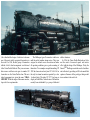
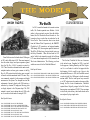
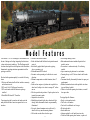
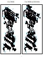
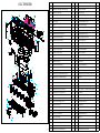
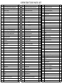
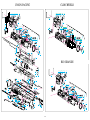
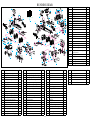
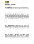
• • • • • • • • Challenger History Challenger…The Model Model Features Sound and DCC Features Operating the Challenger Lubrication and Maintenance Challenger Tender Diagrams Challenger Locomotive Diagrams Page…2 Page…4 Page…5 Page…6 Page…7 Page…10 Page…12 Page…14 The Challenger 4-6-6-4 simple articulated locomotive was born into an era of contradictions. The railroad industry was suffering through the massive economic downturns of the early 1930s, with most railroads barely remaining solvent. Yet, a movement arose that resulted in the development of the pinnacle of steam locomotive design. New locomotive orders with the major erection shops of Alco, Baldwin and Lima were almost non - existent in the years between 1930 and 1933. Most railroads opted to rebuild and refurbish existing equipment in their own shops. In addition, motive power rendered obsolete or surplus by the downturn in traffic found its way to the scrap line. In an effort to capture what little business existed, experimentation reached a fever pitch. These efforts manifested themselves in the introduction of streamlining, the development of diesel-powered, dedicated consist passenger trains and super-power steam locomotives. Super-power steam was the evolution in steam locomotion brought about by a marriage of high tractive effort with high-speed performance. Previously, railroads had either greyhound swift locomotives with limited pulling power or massive, complex locomotives capable of high tractive effort at speeds of around 20 miles per hour. By combining the latest technology with improved understanding of the dynamics of steam power, new classes of locomotives reached the rails. These machines featured large fireboxes supported by either four or six wheel trailing trucks, massive boiler girths that pressed clearance limits, higher boiler operating pressures and the latest in appliances that improved the roadworthiness and thermal efficiencies of the power plant. The Union Pacific Railroad had a unique operational dilemma: The majority of its traffic was moved over long distances between the West Coast and the Midwest through daunting terrain. Almost at the midpoint of the system is Cheyenne, Wyoming and the Sherman Hill grade. Geographically, Cheyenne is located at the juncture between the plains of the Midwest and the foothills of the Rocky Mountain ranges. While not as dramatic as the Allegheny or Sierra grades, the line west of Cheyenne had long runs of 1.2% or better grades. The Union Pacific sought to operate long high-speed service through this challenging geography. For this reason, their best and most modern motive power was allocated to this division. Beginning with double-headed 28-0 Consolidations in the early twentieth century, heavier and more powerful locomotives were used, culminating with the signature Union Pacific threecylinder 4-12-2. While they provided stellar service on the Sherman Hill route, these twelve-coupled locomotives had reached the maximum size for a rigid wheelbase locomotive and required the Union Pacific to look for additional horsepower to increase over-the-road speed. Arthur M. Fetters, general mechanical engineer for the UP, suggested redesigning the successful wheel arrangement of the 4-12-2 as a simple articulated. By splitting the wheelbase between two smaller frames, an advantage would be gained by the ability to add larger drivers to a shorter rigid wheelbase. This resulted in more speed with the added benefit of lighter side rods. These lighter side rods would minimize track damage at higher speeds since the entire mechanism would be easier to balance dynamically. The final complement to this concept would be the ability to add a larger firebox supported by a four wheel trailing truck, further enhancing steaming capabilities. Mr. Fetters and the designers from American Locomotive Company Challenger Locomotive Weights and Dimensions Tractive force 97,350 Lbs. Cylinders, diameter and stroke (4) 21 in. x 32 in. Drivers, diameter 69 in. Total weight of engine 634.500 Lbs. Weight of tender (2/3 loaded) 348,000 Lbs Boiler diameter, first ring inside 94-11/16 in. Length over tube sheets 20 ft. 0 in. Driving wheel base, each 12 ft. 0 in. Total engine wheel base 60 ft. 4 in. Fuel Soft coal/Oil Grate area 132.2 sq. ft. Steam pressure 280 Lbs. Evaporative heating surface, firebox total 554 sq. ft. Evaporative heating surface, tubes and flues 4,038 sq. ft. Superheating surface, type A 1,741 sq. ft. Tender Capacity, centipede 25,000 gal., 28 tons (Alco) finalized the design of what was to become one of the most widely recognized locomotives in the world. In 1936, the first group of locomotives with the 4-6-6-4 wheel arrangement was delivered to the Union Pacific Railroad. They were an immediate success and their roster grew to number 105 locomotives on the Union Pacific alone. This new wheel arrangement was given the name “CHALLENGER”. While the origin of the name is unclear, it proved to be an apt moniker. The Challenger type of locomotive would serve until the end of mainline steam service. They were assigned to railroads across the nation and under all operating conditions gave a good accounting of themselves. Two examples escaped dismantling. UP 3985 has been restored and joins UP 4-8-4 844 as the only two steam locomotives operated by a class 1 railroad today. The other, UP 3977, has been on display in North Platte, Nebraska since 1968 and has recently been refurbished by a group of dedicated railfan volunteers. In 1936, the Union Pacific Railroad and Alco met the needs of increased speeds and tractive effort with the design of the Challenger. Today, the GenesisTM Challenger meets the needs of modelers and collectors by providing an HO scale model that captures all nuances of the prototype, taking model steam realism to the next level. UNION PACIFIC j CLINCHFIELD In 1943, to meet the demands of increased war-time traffic, Rio Grande requested more Baldwin 4-6-6-4s similar to those previously received from this builder. Instead, the War Production Board diverted six Alco locomotives from an order then in production for the Union Pacific. These locomotives were in turn leased from the Defense Plant Corporation by the D&RGW. Classified as L-97 locomotives, and assigned numbers 3800 through 3805, these engines spent the duration of World War II lifting heavy ferrying freight trains over the Rocky Mountains. When the war ended in 1945 and rail traffic levels returned to normal, the half-dozen Union Pacific received its fourth order of Challengers L-97s were deemed surplus and, in 1946, returned to the in 1943, and its fifth order in 1944. These were improved War Assets Administration. The following year, these from the earlier design based upon experience gained workhorses were sold to the Clinchfield Railroad. from the Big Boy 4-8-8-4 locomotive received in 1941. These locomotives featured double smoke stacks, Road Specific Features: centipede tenders and many parts common to the Big Boys. In 1952 engines from both orders were converted G9121 CHALLENGER UNDECORATED UP/RIO GRANDE VERSION to burn oil and were renumbered in the 3700 series. They G9123 CHALLENGER DENVER & RIO GRANDE WESTERN #3802 were commonly assigned to both passenger and freight G9129 CHALLENGER DENVER & RIO GRANDE WESTERN #3804 movements on the system. Two examples survived the replacement of steam by diesels, with 3985 receiving a restoration by volunteer UP employees following years on display adjacent to the Cheyenne depot. The 3985 returned to special service during the early 1980s, with an oil conversion for the tender occurring in 1990. The Carolina, Clinchfield & Ohio was a latecomer to the railroad scene. Completed in 1909, it was built for the purpose of hauling Kentucky and West Virginia coal. As a coal hauler it would at first appear that the high stepping 4-6-6-4s would be out of place in this environment. However, in 1942, the Clinchfield received an order of eight Alco Challengers to handle increased wartime traffic. This first order proved very successful so, in 1947 when six more locomotives became available through the War Assets Administration, Clinchfield acquired them. Originally assigned to the Rio Grande, these engines were numbered 670-675. They are unique in that, shortly after delivery, their double smoke stacks were replaced by large single stacks . Road Specific Features: Road Specific Features: G9122 CHALLENGER UP #3985 (FAN TRIP VERSION) G9125 CHALLENGER UP #3943 COAL & SMOKE DEFLECTORS G9126 CHALLENGER UP #3977 TWO TONE GRAY W/OIL TENDER G9128 CHALLENGER UNDECORATED UNION PACIFIC LATE G9130 CHALLENGER UP #3964 ALL BLACK, COAL G9131 CHALLENGER UP #3975 TWO TONE GRAY W/OIL TENDER G9132 CHALLENGER UP #3958 ALL BLACK, COAL G9133 CHALLENGER UP #3983 TWO TONE GRAY W/OIL TENDER G9120 CHALLENGER UNDECORATED CLINCHFIELD VERSION G9124 CHALLENGER CLINCHFIELD #670 WITH SINGLE STACK G9127 CHALLENGER CLINCHFIELD #672 WITH SINGLE STACK Model Features The Genesis™ 4-6-6-4 Challenger is the culmination of the art of design and tooling integrating the latest innovations in electronic technology. The Challenger model has been developed from its inception as the finest three dimensional operating miniature representation of the prototype available. Enclosed in the premium quality box are the following items: 1. History and Instruction Book that includes a warranty and instruction card 2. HO scale 4-6-6-4 Challenger Locomotive 3. HO scale tender with full electronics package installed 4. Hand Held Wireless DC Controller Upon inspecting the locomotive and tender note the many details that have been incorporated in its construction. Locomotive and tender features • Boiler backhead with full details and printed manual controls. • Individually applied detail parts such as piping, valves, generators, etc. • Blackened metal RP25 wheels. • Eccentric cranks operating on both sides in correct direction. • Minimal compromise on wheel diameter (about 1” only). • Front and rear engines (cylinders and coupled drive wheel sets) both pivot in order to manage 18” radius curves. • Pilot has open/closed positions. Coupler pocket can be inserted to mount coupler. • Adjustable cab windows. • Headlights and tender lights have directional light change, while the number boards are permanently illuminated. • Five-pole, skewed armature motor with two flywheels with very smooth-running features. • Cab hatches can be either closed or open. • See-through running boards. • Each undecorated version includes all parts for that specific version. • Locomotive is smoke-unit-ready. No soldering needed. • 6-pin connector plug between loco and tender. • Current pick-up on all 12 driver wheels and 8 tender wheels. • Consumer-friendly disassembly features for spare part replacement. • Detailed instruction sheets with exploded view drawings and history booklet. • Cabin is closed with opening door feature, or model has open cabin. Prototype Specific Features • Single or twin smoke stacks. • Coal load or oil bunkers. • Coal rack for additional coal storage. • Wood tender deck. • Smoke deflectors. • Ashpans applied to coal fueled versions only. • Closed cab with opening door feature, or open cab. Sound and DCC Features The installation of sound in a locomotive adds a new dimension to operation. Sound makes a technically perfect static model come alive and enhances the experience of operation. You will find that you will no longer ‘run’ the engine but, rather, operate it in the context of your layout. Whether you are using conventional DC control or a DCC system, the incorporation of advanced electronic technology will provide the ultimate railroading experience. The GenesisTM Challenger Locomotive includes a factory installed DCC and sound board with speakers. The board is mounted in the tender. The DCC decoder automatically senses the power supply type (either DC or NMRA compliant DCC system) that is being used and will operate without intervention from the user. Hand-Held Wireless Controller DCC Features: LED Indicator Whistle Bell Stop Decelerate Accelerate Direction Included with the Challenger locomotive is a hand-held wireless controller. When operating on conventional DC, this control unit is designed specifically to allow control of the speed and direction of the locomotive as well as these six individual sound functions: • Bell • Whistle • Water Injector • Air Release • Blower Hiss • Fire Box Door These are more sound features than have been previously available to the conventional DC sound user in any format. The GenesisTM Challenger Locomotive will operate on DC without the use of this hand held, however, only the steam chuff sounds will be available in this operational mode. The decoder provided with the GenesisTM Challenger Locomotive will operate with any NMRA compatible DCC system. The default setting is address 3. The decoder is rated at 2 amps and will support either 2 or 4 digit addresses. The decoder functions are fully programmable by the adjustment of CVs. A CV table is included in the operating instructions. Either 14 speed steps or 28/128 speed steps are supported by this system. Available accessory and sound functions are as follows: • Directional Lighting • Bell • Whistle • Air Release • Coupling • Brake Squeal • Conductor’s Voice • Fire Box Door • Sound On/Off • Sand Release • Water Injector • Blower Hiss • Cylinder Cock/Flange squeal In addition to Function Ø (Directional lighting) there are twelve additional sound functions to allow the operator to capture the full range of unique sounds found on an operating steam locomotive. You can now fully immerse yourself in the complexities of prototype operation and add a new level of realism to your railroading experience. Dual-Function decoder is made by Model Rectifier Corporation for Athearn, Inc. The 12-volt transmitter battery # A23-12, is available at any electronics or office supply store. Your new GenesisTM Challenger Locomotive comes factory equipped with a state-of-the-art Dual Function decoder. This means your locomotive will run on any NMRA compatible DCC system or on any regular DC Train Control (HO power pack). Caution: Do not run your new GenesisTM Challenger Locomotive on any G scale power pack. You may damage the locomotive circuitry. When running on a DC power pack, this locomotive features a wireless radio control. This makes accessing the sound functions and running the locomotive more convenient when following your train around the layout. The transmitter (battery not included) that comes with your locomotive has the following functions: 1. Button 1 will start or stop the bell sounds. 2. Button 2 will operate the steam whistle. 3. Button STP will bring the locomotive to a gradual stop. This is a built in safety feature. Press Button STP while the locomotive is stopped and you will hear the water injector sound. 4. Button 4 will accelerate the locomotive. When the locomotive has reached its maximum speed, pressing Button 4 will activate the sound of the fire box door opening and closing. 5. Button 3 will decelerate the locomotive. Press Button 3 when the locomotive is stopped and you will hear an air release sound. 6. Button 5 (pressed while the locomotive is moving) will slow the locomotive down, change its direction and speed it up. This is also a built in safety feature. Press Button 5 when the locomotive is in idle (25%—35% throttle setting) to activate the blower hiss sound. Note: There are two idle settings that enable various sounds to be controlled while the engine is standing still. To activate "Idle #1" set the power pack's throttle setting at the 25%—35% position, being sure to keep the transmitter's speed regulator setting off. less of the position of the direction switch on the power pack. In "Idle #1" the following sounds can be activated: bell, whistle, water injector, air release, blower hiss 7. When you use the power pack's throttle to control the locomotive’s speed, the top speed will be limited by and fire box door. To access the "Idle #2" setting, set the transmitter’s speed setting. the power pack's throttle to 100% (again, keeping the transmitter's speed regulator off). While in "Idle #2" 8. When you use the transmitter to control the locomotive’s speed, the top speed will be limited by the power the same sounds can be activated with the transmitter, pack's throttle setting. with the exception of the fire box door. 9. If the locomotive's top speed is too low, do not set the power pack's throttle to maximum. We recommend DC Operation-Analog Mode you set the throttle to 60%-70% and use the transmitter To set up your Hand Held Controller and operate you to control the locomotive speed. This will give you the locomotive with a DC power pack, follow these easy directions: best operation range. 10. Never exceed 18 volts D.C. to the track in analog 1. Install the battery in the transmitter. operation. Excessive track voltage may damage the 2. Connect the wires from your DC power pack's "varilocomotive’s circuitry. Never try to operate the locoable track terminals" to your track. motive on A.C. power. 3. Place the locomotive on the track making sure all 11. If the transmitter’s range begins to decrease, the battery needs to be replaced. wheels are aligned correctly to avoid short circuits, which can possibly damage your locomotive circuitry 12. We recommend you always use the power pack's throttle to control the locomotive speed. Not only will and power pack. you get a smoother speed control, but the battery life 4. Turn the switch on the power pack to ON. will be extended. 5. Slowly adjust the throttle until you hear the locomotive begin to idle. Only during idle can you use the 13. Whenever you feel that the locomotive is not operatdirection switch on the power pack to change the ing properly you should move the throttle to zero or locomotive’s direction. Either the headlight or back-up 25%-35% throttle setting (depending on your power light will illuminate to indicate the locomotive’s direcpack) and slowly move the throttle up again to control tion. Once the locomotive begins moving, you cannot the locomotive. use the direction switch on the power pack to change Programming in Analog Mode direction. You can only use transmitter to change the locomotive direction while it is moving. This feature allows you to control another analog locomotive on While in analog mode, you can program the chuff rate and the sound volume. the same track. 6. Your new GenesisTM Challenger Locomotive will always remember its last direction of operation regard- 1. Place the locomotive on track 2. Turn the power switch on the power pack to ON. 3. Slowly turn the throttle until sounds come on. Once sounds begin you have 20 seconds to enter the program mode. 4. Enter the program mode by pressing the Button STP three (3) times. The locomotive will say “program” after each press. After the third “program,” you will be in program mode. 5. Press Button 4 or Button 3 to speed up or reduce the chuff rate, respectively. Each press of the button adjusts the chuff rate up or down by one unit. Each time you will hear the locomotive say “program”. 6. Press Button W to toggle between volume settings. You will hear the locomotive say “program” with the new volume setting. 7. Once finished programming, turn the power switch on the power pack to OFF. This will reset the locomotive and lock in your programming. To resume operation, follow the steps under “DC Operation”. TIPS for Analog Operation 1. Turn up the throttle until sounds start and locomotive idles. 2. Select the locomotive’s direction either by the direction switch on the power pack or by the transmitter. 3. Slowly start your locomotive moving by using the power pack’s throttle to set desired top voltage setting. 4. Once underway, use the transmitter Button 4 to speed up or Button 3 to slow down. Hold down the button until you reach the desired speed. 5. If the top voltage setting at maximum speed is too low, use the power packs throttle to adjust the top voltage setting. 6. To conserve battery, use the throttle to control locomotive speed and use the transmitter to activate sounds. 7. When finished running your locomotive, turn your power pack throttle to OFF and turn off the power pack’s power switch. Any programming changes made in DC analog mode will affect any prior DCC mode settings. Manual Volume Control Located on the top of the tender towards the rear, there are 3 oval hatches. Remove the middle hatch and use a small flat-bladed jeweler’s screwdriver to adjust the volume. Remove this hatch to adjust sound DCC Operation- Digital Mode Additional Information Your new GenesisTM Challenger Locomotive will The dual-function decoder installed in this locomooperate on any NMRA compatible DCC system. The tive should perform well when used with any NMRA dual-function decoder has the following features: compatible DCC system. See your DCC manual on how to program and operate the decoder. For more information about Register/CV’s and their functions, please refer • Synchronized steam chuff with random sounds to the NMRA DCC standards and recommended prac• 1.5 amp capacity • Programmable for either 2 digit, (1-127) or 4 digit, (1- tices, RP-9.2.2. This is available directly from NMRA or on their website at www.nmra.org. 9,999) addresses • Programmable start voltage FCC Compliance • Programmable acceleration rate • Programmable deceleration rate This device complies with Part 15 of FCC rules. • Programmable top voltage Operation is subject to the following two conditions; • Programmable chuff rate 1) This device may not cause harmful interference, and • Programmable volume 2) This device must accept any interference received, • Programmable 14-28/128 speed steps including interference that may cause undesirable opera• Directional lighting (FØ) tion. • 12 accessory sound functions, (F1-F12) • Advanced consisting (CV19) • OPS mode programming Battery Type # A23 12 volt • Compatible with NMRA D.C.C. standard • Complies with Part 15 of F.C.C.Rules Operation The GenesisTM Challenger Locomotive can be oper- ated with the steam sounds on or off. Double clicking your headlight button (FØ) will turn the steam sounds on or off. When the steam sounds are turned off, all associated sounds are also turned off. Programming for DCC Operation - Digital Mode This decoder supports all program methods including register mode, paged mode, CV programming, direct mode and programming on the main (OPS mode programming). Program the locomotive the same way you would program any other NMRA compatible decoder with your DCC system. CV CHART CV REGISTER DESCRIPTION RANGE FACTORY VALUE CV1 R1 Short address 1—127 3 CV2 R2 Start voltage 0—32 0 CV3 R3 Acceleration 0—32 0 CV4 R4 Deceleration 0—32 0 CV5 --- Top voltage 0—32 32 CV29 R5 CV7 R7 CV8 R8 CV17 --- CV18 --- CV19 --- CV52 --- CV64 --- CV105 --- CV106 --- --- R6 STEAM SOUNDS CHART FUNCTION IDLE/MOVING Double click FØ Sounds ON/OFF F1 Bell ON/OFF F2 Whistle F3 Air release F4 Coupling F5 Brake Squeal F6 Conductor F7 Fire Box Door OPEN/CLOSE F8 Sand Release F9 Cylinder Cock/Flange Squeal F10 Water Injector F11 Blower Hiss F12 Sounds ON/OFF Basic --Configuration Manufacturer --Version # Manufacturer --I.D. Long address 192—231 upper byte Long address 0—255 lower byte Advanced 1—127 consist address Sound volume 0 or 1 MIN/MAX Chuff rate User identifier number User identifier number Page number 2 32 143 192 3 0 1 0—10 5 0—255 0 0—255 0 0-31 1 Lubrication and Maintenance of the GenesisTM 4-6-6-4 Challenger The GenesisTM Challenger Locomotive has been carefully engineered to provide years of trouble free operation. However, as with all things mechanical, a small amount of care and maintenance is required to insure the flawless operation of this fine model. These simple procedures will provide the necessary information to give you years of trouble-free enjoyment. Care and Cleaning tact. There should be few cases of erratic performance due to poor contact. However, over time, dirt from the rails will accumulate on the wheel surfaces and will need to be removed to assure peak operation. The use of a cotton swab to apply either alcohol or a good quality track cleaning solution is recommended. Carefully apply the solvents, taking care not to spill any on the painted surfaces. Alternatively, either an ink eraser or ‘Bright Boy’ abrasive block can be used to remove dirt deposits by carefully burnishing the wheel surfaces. When cleaning the wheels, also remove any dirt build up from the metal surfaces on the back rims of the wheels. This will assure that the wiper contacts will maintain good contact with the wheels. Dust and debris are among the leading contributors to poor operation of any miniature mechanism. To Lubrication maintain the quality performance of your locomotive, inspection and cleaning should be performed on a regular This locomotive will arrive pre-lubricated from the basis. A soft bristle brush should be used to remove dust factory and will not need additional lubrication until it from the superstructure. The use of soaps, solvents or has been run for quite some time. When it comes time detergents is not recommended for this purpose as they to lubricate the locomotive, use only light weight oil and gear grease that is plastic compatible. Use a minimum will have a tendency to mar the finish. When not in use it is recommended that the locomo- amount. The plastics used for many of the components, tive and tender be stored in the protective sleeve in which such as the gears and drive lines, make them inherently it was packed. Also, store the wireless controller in the self lubricating. Remember that too much lubrication can locomotive box with the battery removed. be more detrimental to the locomotive than too little. When inspecting the underframe, make sure that all lint and dust are removed from the back of all wheel sets. The main points of lubrication, and type of lubricant Dirt build up in this area will foul the pick-up wipers and are as follows: not allow proper electrical contact, negatively impacting • Axle bearings on the drivers – light oil performance. • Armature bearings on the motors – light oil • Oil light bearings on the worm gear shafts – light oil Wheel Cleaning • Bearings on the centipede tender wheels – light oil • Side rods at the crank pins – light oil TM Challenger Locomotive receives • Gear towers – light gear grease The Genesis electric power from all drivers as well as eight of the ten- By following the exploded drawings, access to each der wheels from both rails. This, coupled with the long of these areas should be easily accomplished. If you are overall wheelbase, provides for excellent electrical con10 not comfortable with disassembling this locomotive for lubrication take it to one of the many Model Railroad hobby shops that can provide this service. Smoke Unit Installation The GenesisTM Challenger Locomotive is designed to accept Seuthe #9 or #10 smoke generator units. These are not provided with the locomotive and may be added by the purchaser at their discretion. If it is decided that smoke units will be installed, carefully follow the installation and operating instructions provided by the smoke unit manufacturer. Genesis does not warranty any defects in these smoke units or damage that may occur to the locomotive through their use. Depending upon the number of smoke stacks on the locomotive, either one or two smoke units will be needed to complete installation. Installation is very easily accomplished: Slide the smoke unit down the smoke stack until it engages the electric contacts inside the boiler. Add a minimal amount of smoke fluid to the unit and operate the locomotive normally. It may take a short amount of time when running to heat up the smoke unit before smoke is produced. This is normal. Coupler Installation The Athearn Genesis Challenger model comes with the swivel coupler installed on the pilot. As on the prototype engines, you can have the coupler exposed on the pilot, or swing it around so that the pilot has no coupler in use. The "coupler" on this part is a dummy (non-operating) coupler. An operating coupler can be installed on the pilot. Simply unscrew and remove this dummy coupler. Once removed, you will note that there are two threaded nuts. An operating coupler should fit in the rearmost hole with no clearance problems, and the coupler and it’s box can be attached using screw #212 (supplied, see drawing). If, however, your choice of coupler does have clearance problems when mounted in the rear threaded nut, simply mount it to the threaded nut further forward. Replacing the Traction Tire or Replacing the Traction Tire Equipped Driver To provide tractive effort that rivals the prototype, two traction tires are factory installed on last set of drivers of the rear engine. To replace a worn or loose traction tire: • Remove the crank pin nuts from the traction tire equipped driver. • Loosen the remaining crank pin screws from the other drivers. • Remove the eccentric crank, main rods, bushing and drive rod from the crank pin on the traction tire equipped driver. • Slide off the traction tire and replace with a new tire. • Reverse the procedure of disassembly. Replacement traction tires are available from your local hobby retailer. To replace a driver: • Remove the crank pin screw and nuts from the side rods. • Remove the side rods and eccentric cranks. • Remove the retaining plate from the bottom of the engine by removing the three retaining plate screws. • Remove the wiper assembly. • Remove the driver assembly. • Replace with new driver assembly making sure that the quartering matches the other drivers on the engine. • Assemble in the reverse order that was used in the disassembly. Replacement parts are available from Athearn Trains to the original purchaser for warranty repairs only. A warranty registration form must be on file at Athearn Trains to honor any parts requests. Use of the exploded drawings in this booklet will greatly assist in the above listed procedures. 11 COAL TENDER 352 350 355 356 353 354 351 352 350 358 348 COAL TENDER with WOOD DECK 349 460 355 356 353 354 351 358 359 357 348 377 349 377 345 346 347 339 338 344 343 345 346 347 339 338 459 357 337 344 343 337 342 336 342 361 341 361 341 340 340 335 335 334 334 333 333 376 376 332 332 375 331 375 309 331 374 328 374 328 308 327 308 327 360 360 360 330 360 329 330 326 329 326 324 323 325 307 324 323 325 307 322 319 318 309 322 319 318 321 321 320 317 320 317 312 311 316 315 312 311 316 315 310 314 310 314 313 313 306 306 303 305 302 303 305 301 304 304 12 302 301 Item # Description OIL TENDER 352 350 355 356 353 354 351 571 570 562 563 358 348 349 357 559 564 565 569 566 568 560 561 377 567 345 346 347 339 338 344 343 337 342 336 361 341 340 335 334 333 376 332 375 331 309 374 328 308 327 360 360 330 329 326 324 323 325 307 322 319 318 321 320 317 312 311 316 315 310 314 313 306 303 305 302 301 304 13 QTY Item # Description QTY 301 Tender lead truck wheel and axle assm. 2 342 Tender front grab irons-type 1 4 302 Centipede side frame mounting screw 3 343 Tender front detail 2 303 Centipede side frame 1 344 Side pipe-right 1 304 Tender coupler screw 1 345 Right tool box-short 1 305 Tender coupler box cover 1 346 Right tool box-long 1 306 Rear coupler 1 347 Tender hold down screw 2 307 Screw 2 348 Tender marker lamps 2 308 Front Tender Weight 1 349 Tender rear light lens (clear) 1 309 Rear Tender Weight 1 350 Tender deck rear handrail 2 310 Tender lead truck side frame 1 351 Tender light bar (clear) 1 311 Tender lead truck spring 1 352 Back-up light lens (clear) 1 312 Tender lead truck washer 1 353 Back-up light base 1 313 Tender coupler box 1 354 Back-up