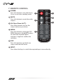
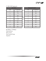
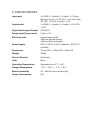
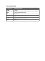
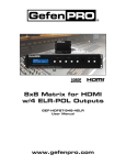
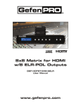
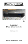
1
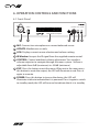
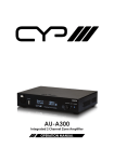
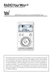
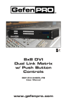
AU-A300
Integrated 2 Channel Zone Amplifier
OPERATION MANUAL
DISCLAIMERS
The information in this manual has been carefully checked and is
believed to be accurate. CYP (UK) Ltd assumes no responsibility for any
infringements of patents or other rights of third parties which may result
from its use.
CYP (UK) Ltd assumes no responsibility for any inaccuracies that may be
contained in this document. CYP (UK) Ltd also makes no commitment to
update or to keep current the information contained in this document.
CYP (UK) Ltd reserves the right to make improvements to this document
and/or product at any time and without notice.
COPYRIGHT NOTICE
No part of this document may be reproduced, transmitted, transcribed,
stored in a retrieval system, or any of its part translated into any language
or computer file, in any form or by any means—electronic, mechanical,
magnetic, optical, chemical, manual, or otherwise—without express
written permission and consent from CYP (UK) Ltd.
© Copyright 2011 by CYP (UK) Ltd.
All Rights Reserved.
Version 1.1 August 2011
TRADEMARK ACKNOWLEDGMENTS
All products or service names mentioned in this document may be
trademarks of the companies with which they are associated.
SAFETY PRECAUTIONS
Please read all instructions before attempting to unpack, install or operate
this equipment and before connecting the power supply.
Please keep the following in mind as you unpack and install this
equipment:
• Always follow basic safety precautions to reduce the risk of fire,
electrical shock and injury to persons.
• To prevent fire or shock hazard, do not expose the unit to rain,
moisture or install this product near water.
• Never spill liquid of any kind on or into this product.
• Never push an object of any kind into this product through any
openings or empty slots in the unit, as you may damage parts inside
the unit.
• Do not attach the power supply cabling to building surfaces.
• Use only the supplied power supply unit (PSU). Do not use the PSU if
it is damaged.
• Do not allow anything to rest on the power cabling or allow any
weight to be placed upon it or any person walk on it.
• To protect the unit from overheating, do not block any vents or
openings in the unit housing that provide ventilation and allow for
sufficient space for air to circulate around the unit.
REVISION HISTORY
VERSION NO. DATE
SUMMARY OF CHANGE
v1.00
First release
09/05/13
CONTENTS
1. Introduction�������������������������������������������6
2. Applications�������������������������������������������6
3. Package Contents����������������������������������6
4. System Requirements���������������������������6
5. Features��������������������������������������������������7
6. Operation Controls and Functions�������8
6.1 Front Panel��������������������������������������������������� 8
6.2 Rear Panel����������������������������������������������������� 9
7. Remote Control����������������������������������� 10
7.1 RS-232 Protocols��������������������������������������11
7.2 RS-232/Telnet Commands��������������������12
8. Connection Diagram�������������������������� 13
9. Specifications�������������������������������������� 14
10. Acronyms������������������������������������������ 15
1. INTRODUCTION
The AU-A300 is a compact 2 channel amplifier that is perfect for matrix
zone amplification or corporate/educational presentations. This solution
provides a flexible and versatile input/output structure, enabling a wide
range of sources and systems to integrate with the product. It also boasts
some unique features including a bespoke HDMI pathway with audio
embedding and an analogue line output that can either be fixed or
variable level. With these and other more common features it's an ideal
amplifier for many different installation scenarios.
2. APPLICATIONS
Matrix Zone Audio Routing and Amplification
Corporate events
Educational Presentation
Stereo Ceiling Speaker Systems
Analogue to Digital and Digital to Analogue Conversion
HDMI Audio Embedding and de-embedding
3. PACKAGE CONTENTS
1× Integrated Zone Amplifier
1× IR Receiver
1× Remote Control CR-126
1× 24V/ 3.75A DC Power Adaptor and Power Cable
Operational Manual
4. SYSTEM REQUIREMENTS
Input a wide variety of audio and HDMI sources such as DAB radios,
HDTVs, Sonos systems, PCs, Set-top Boxes and output to speakers, an
additional AU-A300 or other amplifiers.
6
5. FEATURES
30 watts per channel Digital Stereo Amplifier
Inputs: 2×HDMI, 1×L/R Analogue Stereo, 1×Optical digital audio,
1×Coaxial digital audio, 1×3.5mm mini-jack, 1×Microphone (XLR)
Outputs: Stereo speaker terminals, 1×HDMI, 1×Optical digital audio,
1×Coaxial digital audio, 1×L/R Analogue Stereo
Control via IR (Remote and IR Receiver input), RS-232 or IP (Telnet)
Dedicated XLR microphone input with independent volume control
Analogue to Digital and Digital to Analogue Conversion
HDMI Audio Embedding and de-embedding
Compact design supplied with wall brackets
Analogue line output selectable to be either fixed or variable output
level
Note: Does not support the decoding of Dolby® Digital signals
7
6. OPERATION CONTROLS AND FUNCTIONS
6.1 Front Panel
MIC
PUSH
UPDATE
Coaxial In
44.1K
->
CONTROL EXIT POWER
-20.0 dB
44.1K
Integrated Zone Amplifier
1
2
3
4
5
6
7
1 MIC: Connect to a microphone or a mono balanced source
2 UPDATE: Manfacturer use only.
3 LCM: Displays current source selection and volume setting.
4 IR Window: Accepts the IR signal from the supplied remote control.
5 CONTROL: Control and direct volume adjustment. Turn to adjust
volume output or to navigate through the menu system. Volume is
adjustable from 0 dB (maximum) to −80 dB (minimum)
6 EXIT: Press this button to exit the menu. When not in the menu press
this button to mute the output, the LED will illuminate in red. Press it
again to unmute.
7 POWER: Press this button to turn on the device, the LED will
illuminate in blue to indicate that it is powered. Press it again to switch
to standby mode, the LED will turn red to indicate that it is in standby.
8
6.2 Rear Panel
3
5
6
8
10
11
RCA
CONTROL
IR IN
HDMI OUT
1
2
LINE IN
RS-232
HDMI IN 1
COAX.
R
IN
L
R
SPEAKER
OPT. OUT COAX.
-
R
+
OPT.
IN
HDMI IN 2
4
7
-
OUT
L
L
+
DC 24V
9
12
1 IP CONTROL: Connect to an active network with RJ-45 cable for telnet
control.
2 HDMI OUT: Connect to HDTV/monitor for both audio and video
display.
3 IR IN: Connect the IR receiver included in the package for receiving
the IR signal from the device’s remote control.
4 HDMI IN 1& 2: Connect to HDMI source equipment such as a Set-top
Box or Blu-ray player.
5 RS-232: Connect to a PC/Laptop or control system with D-Sub 15pin
cable for RS-232 control.
6 LINE IN: Connect to an audio source with 3.5mm mini-jack cable for
stereo audio signal input.
7 OPT. & COAX. OUT: Digital audio output. Connect to additional
amplifiers or active speakers.
8 OPT. & COAX. IN: Connect to source equipment such as a Set-top-box
or games console with an optical or coaxial digital output.
9 R/L SPEAKER: Connect to speakers with standard speaker cable.
10 R/L IN: Connect to audio source equipment with an RCA cable for
analogue stereo audio input.
11 R/L OUT: Connect L/R output to active speakers or an additional
AU-A300 with an RCA cable for analogue stereo audio output.
12 DC 24V: Connect the 24V DC power supply to the unit and plug the
adaptor into an AC outlet.
9
7. REMOTE CONTROL
1 POWER:
Press this button to turn the device
On or to set it into standby mode.
POWER
1
2
MENU
2 MUTE:
Press this button to mute the audio
output.
MUTE
3
4
EXIT
VOL.
5
3 Vol. Up or Down (▲▼):
Press these buttons to turn the
output volume up or down.
4 MENU:
Press this button to enter the OSD
MENU then press the ▲&▼ buttons
to select the required option
and press it again to confirm the
selection.
5 EXIT:
HDMI 1
HDMI 2
OPTICAL
LR
COAXIAL
LINE
6
INPUT
CR-126
Press this button to go back one
step or exit from the menu.
6 INPUT:
Press these hot keys to switch the required input source directly.
10
7.1 RS-232 Protocols
AU-A300
Remote Control
PIN
Assignment
PIN
Assignment
1
NC
1
NC
2
Tx
2
Rx
3
Rx
3
Tx
4
NC
4
NC
5
GND
5
GND
6
NC
6
NC
7
NC
7
NC
8
NC
8
NC
9
NC
9
NC
►
◄
Baud Rate: 115200bps
Data bit: 8 bits
Parity: None
Flow Control: None
Stop Bit: 1
11
7.2 RS-232/Telnet Commands
Command
Description
PWR 0/1
POWER CONTROL 0:OFF / 1:ON
SOURCE 0~5
SOURCE IN SELECTION 0:HDMI 1, 1:HDMI2, 2:OPT,
3:COAX, 4:LINE IN, 5:RCA IN
VOL 0~80
OUTPUT VOLUME SETTING 0~80dB
MUTE 0/1
OUTPUT VOLUME MUTE CONTROL 0:UNMUTE, 1:MUTE
MICVOL 0~60
MIC VOLUME CONTROL 0~60dB
MICMUTE 0/1
MIC VOLUME MUTE CONTROL
MICSET
0: OFF, 1:NORMAL, 2:PHANTOM, 3: LINE
FADEFAULT
FACTORY DEFAULT SETTING
IPCONFIG
PRINT THE IP CONFIGURATION TO THE SCREEN
RESETIP
RESET THE IP CONFIGURATION TO FACTORY DEFAULTS
SIPADD
SET THE IP ADDRESS
SNETMASK
SET THE NET MASK ADDRESS
SGATEWAY
SET THE GATEWAY ADDRESS
SHTTPPORT
SET THE HTTP COMMUNICATION PORT
STELNETPORT
SET THE TELNET COMMUNCATION PORT
HELP
DISPLAY LIST OF COMMANDS
?
DISPLAY LIST OF COMMANDS
Note: RS-232 commands will be not executed unless followed by a carriage
return. All commands are case-sensitive.
12
8. CONNECTION DIAGRAM
Smart Phone or
Tablet
Amplifier
PC or RS-232
Control System
Analogue
Stereo Input
Digital Optical &
Coaxial input
RS-232
CD Player
Analogue
Stereo
Input
IR Receiver
2nd AU-A300
RCA
CONTROL
60°
3m
m
7m
m
IR IN
RS-232
HDMI OUT
HDMI IN 1
LINE IN
COAX.
R
IN
L
R
SPEAKER
OPT. OUT COAX.
-
R
+
OPT.
IN
HDMI IN 2
OUT
L
L
+
-
3m
Analogue Stereo Output
Modem/Router
RCA
CONTROL
IR IN
HDMI OUT
RS-232
HDMI IN 1
LINE IN
COAX.
R
IN
L
R
SPEAKER
OPT. OUT COAX.
-
R
+
OPT.
IN
HDMI IN 2
-
OUT
L
L
+
DC 24V
Power Supply
Speaker
Level
Output
CAT
Cable
Optical
Stereo
Output
Speakers
Active Speakers
Optical
Stereo
Output
HDMI
Output
HDTV
HDMI
Input
HDMI
Input
Amplifier
DVD/Blu-ray Player
Set-top Box
13
DC 24V
9. SPECIFICATIONS
Input port
2× HDMI, 1× Optical, 1× Coaxial, 1× 3.5mm
Mini-jack Line in, 1× R/L RCA, 1× D-Sub 15pin
(RS-232), 1× RJ-45 (Control), 1× IR
Output port
1× HDMI, 1× Optical, 1× Coaxial, 1× R/L RCA,
1× R/L
Digital Audio Input/Output
LPCM 2CH
Stereo Input/Output Level
2 Vrms ± 0.2
ESD Protection
Human body model:
±8kV (air-gap discharge)
±4kV (contact discharge)
Power Supply
24V/ 3.75A DC (US/EU standards, CE/FCC/UL
certified)
Dimensions
255mm(W) × 170mm(D) × 48mm(H)
Weight
1060g
Chassis Material
Aluminum
Color
Black
Operating Temperature
Operating from 0 °C ~ 40°C
Storage Temperature
−20 ˚C ~ 60 ˚C / −4 ˚F ~ 140 ˚F
Relative Humidity
20 ~ 90% RH (non-condensing)
Power Consumption
9 W
10. ACRONYMS
ACRONYM
COMPLETE TERM
COAX
Coaxial
DAB
Digital Audio Broadcasting
HD
High Definition
HDMI
High-Definition Multimedia Interface
OLED
Organic Light-Emitting Diode
OPT
Optical
CIE-Group Ltd Widdowson Close Blenheim Industrial Estate Nottingham NG6 8WB
Tel: +44 (0) 115 977 0075 | Fax: +44 (0) 115 977 0081
Email: [email protected]
www.cie-group.com