1
Getting Started
S
E
C
T
I
O
N
2
The following sections provide a thorough description of how to
wire and configure devices and zones.
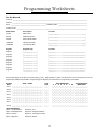
Programming Worksheets should be filled out completely before
attempting to program the system.
2.1
Step 10: Testing the System
The panel must be thoroughly tested to ensure that all features
and functions are operating as programmed.
Installation Steps
The following steps are provided to assist you with installing the
panel. We suggest that you read this section completely before
you begin. Once you have an overall understanding of the
installation process, carefully work through each step. Working in
this manner will reduce the number of problems as well as the
amount of time required for a complete installation.
Step 1: Create a Layout
Draw a rough sketch of the building to get an idea of where all
alarm detection devices, keypads and other modules are to be
located.
2.2
Terminal Descriptions
Battery Connection
A 12V 4Ah rechargable battery is used as a back up source of
power in the event of an AC power failure. The battery also
provides additional current when the panel’s demands exceed
the power output of the transformer, such as when the panel is
in alarm.
Do not connect the battery until all other wiring is
complete. Connect the battery before connecting
the AC.
Step 2: Mounting the Panel
Locate the panel in a dry area close to an unswitched AC power
source and the incoming telephone line. Before attaching the
cabinet to the wall, be sure to press the four circuit board
mounting studs into the cabinet from the back. After you have
attached the cabinet to the wall, stick the provided DSC logo
sticker on the front of the cabinet.
Connect the RED battery lead to the positive battery terminal;
connect the BLACK lead to negative.
AC Terminals – AC
The panel requires a 16.5 volt, 40 VA transformer. Connect the
transformer to an unswitched AC source and connect the
transformer to these terminals.
You must complete all wiring before connecting
the battery, or applying AC to the panel .
Step 3: Wiring the Keybus (Section 2.3)
Wire the Keybus to each of the modules following the guidelines
provided in Section 2.3 of this manual.
Do not connect the transformer until all other
wiring is complete.
Auxiliary Power Terminals – AUX+ and AUXThese terminals provide up to 550 mA of additional current at 12
VDC for devices requiring power. Connect the positive side of
any device requiring power to the AUX+ terminal, the negative
side to AUX- (ground). The AUX output is protected. This means
that if too much current is drawn from these terminals (such as
a wiring short), the panel will temporarily shut off the output until
the problem is corrected.
Step 4: Zone Wiring (Section 2.8)
You must power down the control panel to complete all zone
wiring. Please refer to Section 2.8 when connecting zones using
normally closed loops, single EOL resistors, double EOL resistors,
Fire zones and Keyswitch Arming zones.
Step 5: Complete Wiring (Section 2.2)
Complete all other wiring including bells or sirens, phone line
connections, and ground connections following the guidelines
provided in Section 2.2 (“Terminal Descriptions”).
Bell Output Terminals – BELL+ and BELL(Section 3.4)
These terminals provide up to 700 mA of continuous current at
12 VDC for powering bells, sirens, strobes or other warning-type
equipment. Connect the positive side of any alarm warning
device to BELL+, the negative side to BELL–. Please note that
the Bell output is protected: if too much current is drawn from
these terminals (such as a wiring short), the Bell PTC will open.
Three amps can be drawn for short periods only.
The Bell output is supervised. If no alarm warning devices are
in use, connect a 1000Ω resistor across BELL+ and BELL– to
prevent the panel from displaying a trouble condition. For more
information, please refer to Section 3.4 (“[✱] [2] Trouble Display”).
The bell is programmed by default to terminate after four
minutes. The Bell Cutoff time can be adjusted in programming
section [005] (“System Times”).
Step 6: Power up the Control
Once all zone and Keybus wiring is complete, power up the
control panel. First, connect the red battery lead to the positive
terminal and the black lead to negative. Then, connect the AC.
Connect the battery before connecting the AC.
The panel will not power up on the battery
connection alone.
Step 7: Keypad Assignment (Section 2.5)
In order for keypads to be properly supervised, each must be
assigned to a different slot. Please follow the guidelines provided
in Section 2.5 when assigning keypads.
Step 8: Supervision (Section 2.6)
The supervision of every module by the panel is automatically
enabled upon power up. Please verify that all modules appear
on the system according to the instructions in Section 2.6.
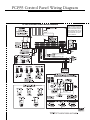
Keybus Terminals – AUX+, AUX-, YEL, GRN
(Section 2.3)
The Keybus is used by the panel to communicate with modules
and vice versa. Each module has four Keybus terminals that
must be connected to the four Keybus terminals on the panel.
For more information, see Section 2.3 (“Keybus Operation and
Wiring”).
Step 9: Programming the System (Sections 4 and 5)
Section 4 explains how to program the panel. Section 5 contains
a complete description of the various programmable features,
which options are available and how they function. The
3