1
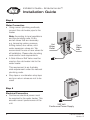
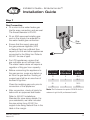
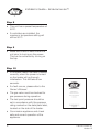
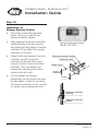
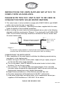
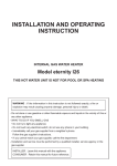
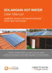
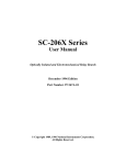
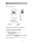
Installer’s Guide
Important INFORMATION
Read This Document First
On completion, sign and leave with owner
Gas continuous flow water heater
Models: 26XL
26XN
Installation by a licensed tradesperson and in
accordance with:
• AS/NZS 3500.4 “National Plumbing &
Drainage Code Hot Water Supply Systems
– Acceptable Solutions”
• AS5601/AG601 Gas Installation
• Adherence to local authority and OH&S
regulations
• Victorian PIC Requirements
For advice, repairs and service, call:
1300 365 115 (Australia)
0800 729 389 (New Zealand)
Specifications and materials may change without notice
Effective for Endurance continuous flow water heaters manufactured and sold after 1st Sept 2009.
Part No: IG090701
Version: B
Installer’s Guide – Endurance six™
Installation Guide
Step 1
• Arrive at site, park vehicle as close as
allowable to installation, and conduct
a safety audit.
• Safety audits can also be known as
Work Method Statements (WMS) or
Job Site Analysis (JSA).
Note – do not commence a
job where the risks can’t be
controlled.
Step 2
• The existing water heater (if
applicable) should be drained and
removed in a responsible manner.
Note: Do not drain on to grass or
garden beds.
Step 3
• This heater is approved for
outdoor installation only – it is
not suitable for indoor use.
• Safely install new heater in an
appropriate location, in accordance
with all plumbing and building
regulations.
2
Window
Endurance
Door
Refer to AS5601 for detailed installation instructions
Part No: IG090701
Version: B
Installer’s Guide – Endurance six™
Installation Guide
• Refer to the Owner’s Manual and
AG 601 for detailed installation
instructions.
• Plan hot water pipework to ensure
optimum flow rates to all outlets.
Step 4
• Check labels located on the unit’s
side for:
a. maximum inlet water pressure; a
Pressure Limiting Valve may be
required.
b. gas supply pressure requirements
(minimums = 1.13kPa for Natural
Gas, 2.75kPa for LPG)
c. gas type – is the unit set up for
the gas supplied to the property?
Labels
• Ensure that the property’s gas
meter is able to supply sufficient
volume of gas and pressure in the
event of all gas appliances on site
operating simltaneously at maximum
gas consumption levels. For LPG
installations, confirm bottle size is
adequate. This water heater uses
199 MJ/h of gas.
Part No: IG090701
Version: B
3
Installer’s Guide – Endurance six™
Installation Guide
Step 5
Water Connection
• Using correct plumbing methods,
connect the cold water pipe to the
heater.
Note: According to local regulations
and the plumbing code, fit any
and all valves that are necessary
e.g. tempering valves, pressure
limiting valves, duo valves, cold
water expansion valves etc. We
recommend the use of new valves for
all Installation. Please refer plumbing
code and/or local requirements.
Hot
Water
Outlet
Cold
Water
Inlet
• A Gate Valve or Ball Valve must be
used on the cold water inlet to the
water heater.
This requirement is an Australia
wide requirement under the national
plumbing code.
• Stop taps or combination stop taps
and non-return valves are not to be
used!
Step 6
Electrical Connection
• Continuous electrical power must
be supplied to the water heater. This
ensures correct performance of the
unit.
4
240 Volt
Continuous Power Supply
Part No: IG090701
Version: B
Installer’s Guide – Endurance six™
Installation Guide
Step 7
Gas Connection
• Fit a union to the water heater gas
inlet for easy connection and removal.
The thread diameter is R¾/20.
• Fit an AGA approved isolating gas
cock in the supply line adjacent to
the water heater gas connection.
Gas
Valve
• Ensure that the supply pipe and
the gas pressure regulator (LPG
or Natural Gas) has sufficient flow
capacity for this and other appliances
connected to the fitting line. Refer to
AG 601 for size of pipe.
• For LPG appliances, ensure that
gas cylinders are of sufficient size.
The water heater alone will require a
regulator of 4kg per hour capacity.
• Before connecting the appliance to
the gas service, purge any debris or
air from the gas service. Venting of
purged gas shall be an area free of
sources of ignition.
Close the isolating gas cock prior to
connection of the appliance.
• After connection, check all joints for
leaks with an approved leak tester.
Nominal Pipe
Size in mm
Straight Length
Of Pipe Metres
Hourly Rate
in MJ/h
13
4
43.0
18
4
82.2
20
4
142.0
25
4
313.0
Note: The Endurance six requires 199 MJ/h for the
customer to get the full performance benefit.
Refer to AG 601 Installations
Standard for pipe sizing details. For
your assistance, we have included
the pipe sizing from AG 601 for
copper tube using Natural Gas in the
table in the margin.
Part No: IG090701
Version: B
5
Installer’s Guide – Endurance six™
Step 8
• This unit has a preset temperature of
50°C.
• If controllers are installed, the
maximum temperature setting will
still be 50°C.
Step 9
• Make sure there is water inside the
unit prior to turning on the power.
This can be achieved by turning on
the tap.
Step 10
• If the water heater has been installed
correctly, when the power is turned
on the heater will go through
initialisation. This will take a few
seconds.
• If a fault occurs, please refer to the
Owner’s Manual.
• The gas valve must be checked for
gas pressure during operation.
• The test point pressure should be
set in accordance with the pressure
rating marked on the data plate label,
located on the side of the heater.
• Commission appliance and check
safe and correct operation of the
appliance.
6
Part No: IG090701
Version: B
Installer’s Guide – Endurance six™
Installation Guide
Step 11
Installation Of Main
Remote Control
• Detach the fitting bracket from Main
remote controller by sliding it down.
Bad examples
• Attach the fitting plate to wall.
• Install conduit inside of wall in
advance and secure the wiring box.
• Pass remote controller cables
through conduit.
Chemicals
Do
NotRemote Control
Main
Model CMR-2252
• Then pass the cables through the
hole of the fitting bracket and pull
them out.
• Attach the fitting bracket with screws
adjusting the screw hole to the wiring
box.
Remote controller
Remote controller
fitting bracket
• Connect the remote controller
cables to the terminal for the remote
controller of PCB.
• If controllers are installed, the
maximum temperature setting will
still be 50°C.
Wiring box
controllerPart No: IG090701
acket
Version: B
Slot
Terminal
Hook
7
Installer’s Guide – Endurance six™
Installation Guide
Step 12
Installation of
Shower Remote Control
• Drill a hole (more than diameter
about 12mm) in a wall for the
remote controller cables.
•
After passing the remote controller
cables through the hole, remove
the packing’s back paper of remote
controller. Then attach the remote
controller to the wall.
•
Detach both end covers of remote
controller and fix the remote
controller to the wall with wood
screws (2 pcs) in the screw holes
provided. (You can detach the
covers with catching the bottom
corner’s slot with nail.)
•
Do not tighten the screws
excessively, as the screw hole may
be damaged. In case of mounting
the Remote
remote controller
controllercables
on tile, cement
Expansion
bolt
or mortar, use
an expansion
bolt.
Wood screw
Cover
Shower Remote Control
Model YST-2252
Remote controller cables
Expansion bolt
Wood screw
Cover
Cover
Remote controller
packing
Remote controller
cables
Cover
8
Part No: IG090701
Version: B
Installer’s Guide – Endurance six™
Installation Declaration
Location of Installation: ...........................................................................................
...............................................................................................................................
...............................................................................................................................
Tank Serial Number: ...............................................................................................
Tank Model Number: ..............................................................................................
Date Installed: ............................
Dux Hot Water terms and conditions of warranty will only apply if the below is signed
by the installer. This notifies Dux Hot Water that all the requirements of proper
installation have been carried out by the installer in accordance with the Dux Hot
Water Installation Commissioning Checklist and all other requirements noted in the
Dux Hot Water Owner’s Manual supplied with the solar water heater.
Upon completion of installation, this document should be given to the home owner
in its entirety. When required by Dux Hot Water the home owner will provide this
document as evidence that the installation of the solar water heater was carried out
in accordance with Dux Hot Water installation requirements.
Declaration
I have installed the Dux Hot Water solar water heater in accordance with the above
instructions. If the instructions have not been followed then I understand that the
Dux Hot Water terms and conditions of warranty will be void.
Name:.....................................................................................................................
Signed: . .................................................................................................................
Company: ..............................................................................................................
Date: ..........................................
Part No: IG090701
Version: B
9
Installer’s Guide – Endurance six™
10
Part No: IG090701
Version: B
Installer’s Guide – Endurance six™
Part No: IG090701
Version: B
11
Installer’s Guide – Endurance six™
Gas continuous flow water heater
Models: 26XL
26XN
For advice, repairs and service, call:
1300 365 115 (Australia)
0800 729 389 (New Zealand)
Part No: IG090701
Version: B
INSTRUCTIONS FOR UNITS SUPPLIED SET AT 50℃ TO
COMPLY WITH AS 3498-2009.
PLEASE NOTE THIS 50℃ UNIT IS NOT TO BE USED IN
CONJUNCTION WITH SOLAR WATER HEATERS.
1) This water heater is to be installed to comply with AS/NZS 3500.4 and AS5601
codes and any local by laws or regulations.
2) Please refer to the Installation / Operating instructions supplied with this water
heater for details of the installation procedure.
3) When installing the water heater hot water pipework please refer to the following
pipework installation requirements (Diagram 1) to comply with the AS3498-2009
code. The first outlet valve (tap) should be a minimum of Four (4) metres from
the water heater outlet.
Valve 1.
Minimum of distance of pipework
L to Valve 1 is Four (4) metres.
Hot water outlet
Outlet to deliver hot
water to sanitary
fixtures
L
Pipe size 20mm
Valve 2.
Diagram 1.
The hot water supply pipework is required to be insulated with Ensolex or similar
insulation from the hot water heater to all outlet points within the building.
COMMISSIONING THE WATER HEATER.
1) After completion of the water heater installation the following commissioning
procedure is to be implemented.
a) Before turning on the water heater power supply and gas supply, purge all
air from the Hot water supply pipework.
b) Turn on the power, allow 30 seconds for the water heater to check safety
functions. Turn on the gas supply.
c) Turn on Valve 1. to a minimum flow rate (approximately 3 l/m) and allow
the water heater to operate for approximately Two(2) minutes and check the
flowing water temperature using a digital thermometer.
d) Repeat above procedure (c) at the maximum possible flow rate.
e) The water temperature will be delivered at 48-50℃ continuously.
f ) If the water heater does not deliver water at this temperature contact you
supplier or DUX Hot Water on 1300 365 115 for advice.
PLEASE SEE REVERSE SIDE.
20616780
MR PLUMBER.
PLEASE NOTE this Dux Endurance unit is supplied factory
set at 50℃ outlet hot water temperature to comply with
the requirements of AS 3498-2009.
This Endurance hot water unit does not require a tempering
valve to be installed.
Installation instructions.
Please follow all the installation instructions in the Dux Endurance Installation and
operating instructions handbook and the following additional instructions for the
Hot water outlet connection.
1. When connecting the hot water supply to the fixtures in the property a minimum
of Four (4) Metres of pipework must be used between the outlet of the Dux En durance water heater and the first tap and outlet. See Diagram below 1.
*Pipe size is nominal 18 mm
from hot water outlet to the
first tap or outlet.
TOTAL LENGTH TO FIRST TAP OR OUTLET IS
REQUIRED TO BE A MINIMUM OF FOUR (4)
METRES FROM THE OUTLET CONNECTION OF
THE WATER HEATER.
*
GAS
COLD
HOT
Diagram 1.
FIRST TAP OR OUTLET
2. The Hot water line should be insulated with Ensolex or similar pipe insulation.
3. When the installation is completed the temperature is to be tested at the taps to
confirm the water temperature does not exceed the required 50℃ setting.
PLEASE SEE REVERSE SIDE.