1
CONTENTS
Technical data…..………………………………………………………..
General safety rules…….………………………………………………..
Specific safety rules for bench grinder..…………………………………
Electrical information…………………………………………………...
Know your bench grinder………………………………………………..
Assembly…………………………………………………………………
Operation………………………………………………………………...
Maintenance……………………………………………………………..
Troubleshooting………………………………………………………….
Exploded view……………………………………………………………
Parts list…………………………………………………………………
Warranty…………………………………………………………………
2
3
5
7
9
10
11
12
13
14
15
16
TECHNICAL DATA
8" Slow Speed Bench Grinder
Model:
Motor:
Speed:
Wheel size:
Arbor size:
Wheel Grits:
Weight:
4286
120 V, 60 Hz, 3A
1750 RPM (no load)
8"x1"
5/8"
#120 (Fine) / #60 (Medium)
36 lb
2
GENERAL SAFETY RULES
GENERAL SAFETY INSTRUCTIONS
Operating a bench grinder can be dangerous if safety and common sense are ignored. The operator must be
familiar with the operation of the tool. Read this manual to understand this bench grinder. DO NOT operate
this bench grinder if you do not fully understand the limitations of this tool. DO NOT modify this bench
grinder in any way.
BEFORE USING THE BENCH GRINDER
WARNING: To avoid serious injury and damage to the tool, read and follow all of the Safety and
Operating Instructions before operating the bench grinder.
WARNING:
1. SOME DUST created by using power tools contains chemicals known to the State of California to cause
cancer, birth defects, or other reproductive harm.
Some examples of these chemicals are:
• Lead from lead-based paints.
• Crystalline silica from bricks, cement, and other masonry products.
• Arsenic and chromium from chemically treated lumber.
Your risk from these exposures varies depending on how often you do this type of work. To reduce your
exposure to these chemicals, work in a well-ventilated area with approved safety equipment such as dust
masks specially designed to filter out microscopic particles.
2. READ the entire owner’s manual. LEARN how to use the tool for its intended applications.
3. GROUND ALL TOOLS. If the tool is supplied with a three-prong plug, it must be plugged into a
three-contact electrical receptacle. The third prong is used to ground the tool and provide protection
against accidental electric shock. DO NOT remove the third prong.
4. AVOID A DANGEROUS WORKING ENVIRONMENT. DO NOT use electrical tools in a damp
environment or expose them to rain.
5. DO NOT use electrical tools in the presence of flammable liquids or gasses.
6. ALWAYS keep the work area clean, well lit, and organized. DO NOT work in an environment with floor
surfaces that are slippery from debris, grease, and wax.
7. KEEP VISITORS AND CHILDREN AWAY. DO NOT permit people to be in the immediate work
area, especially when operating the electrical tool.
8. DO NOT FORCE THE TOOL to perform an operation for which it was not designed. The tool will do
a safer and higher quality job by only performing operations for which it was intended.
9. WEAR PROPER CLOTHING. DO NOT wear loose clothing, gloves, neckties, or jewelry. These
items can get caught in the machine during operations and pull the operator into the moving parts.
Longhaired users must wear a protective cover on their hair to prevent it from contacting any moving
parts.
10. CHILDPROOF THE WORKSHOP AREA by removing switch keys, unplugging tools from the
electrical receptacles, and using padlocks.
11. DO NOT use electrical tools in the presence of flammable liquids or gasses.
3
12. ALWAYS UNPLUG THE TOOL FROM THE ELECTRICAL RECEPTACLE when making
adjustments, changing parts, or performing maintenance.
13. KEEP PROTECTIVE GUARDS IN PLACE AND IN WORKING ORDER.
14. AVOID ACCIDENTAL STARTING. Make sure that the power switch is in the OFF position before
plugging in the power cord to the electrical receptacle.
15. REMOVE ALL MAINTENANCE TOOLS from the immediate area prior to turning
on the Bench Grinder.
16. USE ONLY RECOMMENDED ACCESSORIES. Use of incorrect or improper
accessories could cause serious injury to the operator and damage to the tool. When in doubt, check the
instruction manual that comes with that particular accessory.
17. NEVER LEAVE A RUNNING TOOL UNATTENDED. Turn the power switch to the OFF position.
Do not leave the tool until it has come to a complete stop.
18. DO NOT STAND ON A TOOL. Serious injury could result if the tool tips over or you accidentally
contact the tool.
19. DO NOT store anything above or near the tool to ensure that no one stands on the tool for better reach.
20. MAINTAIN YOUR BALANCE. DO NOT extend yourself over the tool. Wear oil resistant rubber
soled shoes. Keep floor clear of debris, grease, and wax.
21. MAINTAIN TOOLS WITH CARE. Always keep tools clean and in good working order. Keep all
blades and tool bits sharp.
22. EACH AND EVERY TIME, CHECK FOR DAMAGED PARTS PRIOR TO USING THE TOOL.
Carefully check all guards to see that they are not damaged and properly performing their intended
functions. Check for alignment, binding, or breaking of moving parts. A guard or other part that is
damaged should be immediately repaired or replaced.
23. CHILDPROOF THE WORKSHOP AREA by removing switch keys, unplugging tools from the
electrical receptacles, and using padlocks.
24. SECURE ALL WORK. Use clamps or jigs to secure the workpiece. This is safer than attempting to hold
the workpiece with your hands.
25. STAY ALERT! WATCH WHAT YOU ARE DOING AND USE COMMON SENSE WHEN
OPERATING A POWER TOOL. DO NOT USE A TOOL WHILE TIRED OR UNDER THE
INFLUENCE OF DRUGS, ALCOHOL, OR MEDICATION. A moment of inattention while
operating power tools may result in serious personal injury.
26. ALWAYS WEAR A DUST MASK TO PREVENT INHALING DANGEROUS DUST OR
AIRBORNE PARTICLES including wood dust, crystalline silica dust and asbestos dust. Direct
particles away from face and body. Always operate tool in a well-ventilated area and provide for proper
dust removal. Use dust collection system wherever possible. Exposure to dust may cause serious and
permanent respiratory damage or other injury, including silicosis (a serious lung disease), cancer, and
death. Avoid breathing and prolonged contact with dust. Allowing dust to get into your mouth, eyes, or
onto your skin may result in absorption of harmful material. Always use properly fitting
NIOSH/OSHA-approved respiratory protection for dust exposure. Wash exposed areas with soap and
water.
27. USE SAFETY GOGGLES AT ALL TIMES that comply with ANSI Z87.1. Normal safety glasses only
have impact resistant lenses and are not designed for safety. Wear a face or dust mask when working in a
dusty environment. Use ear protection, such as plugs or muffs, during extended periods of operation.
4
SPECIFIC SAFETY RULES FOR BENCH GRINDER
1. USE GRINDING WHEELS suitable for the speeds of the grinder.
2. STAND BESIDE the bench grinder during start-up, not directly in front.
3. DO NOT REMOVE THE WHEEL GUARD.
4. DO NOT USE THE GRINDING WHEEL TO CUT ANYTHING.
5. DO NOT USE ANYTHING TO STRESS THE GRINDING WHEEL.
6. USE A GRINDING WHEEL DRESSING TOOL to shape or remove glaze from grinding wheels.
7. ADJUST DISTANCE between wheel and tool rest to maintain at most a 1/8-inch (3.2 mm) separation as
the diameter of the wheel decreases with usage.
8. CONNECT TO A SUPPLY CIRCUIT protected by a circuit breaker or time-delay fuse.
9. SECURE THE BENCH GRINDER to its supporting surface to prevent the grinder from tipping over,
sliding, or walking on its supporting surface.
• Replace a cracked wheel immediately.
• Always use the guards and eye shields.
• Do not overtighten the wheel nut.
• Use only flanges furnished with this grinder.
10. ALWAYS INSPECT GRINDING WHEELS prior to use for cracks, missing pieces, etc. Replace
wheel immediately before use if imperfections are present.
11. USE ONLY GRINDING WHEELS that comply with ANSI B7.1 and rated greater than 3550 RPM.
12. GUARD AGAINST ELECTRICAL SHOCK by preventing body contact with grounded surfaces. For
example: pipes, radiators, ranges, refrigerator enclosures.
13. DO NOT use wheels with incorrect size holes. NEVER use wheel washers or wheel screws that are
defective or incorrect, and NEVER touch a grinding wheel or other moving parts.
14. NEVER reach to pick up a workpiece, a piece of scrap, or anything else that is in or near the grinding path
of the wheel.
15. AVOID AWKWARD OPERATIONS AND HAND POSITIONS where a sudden slip could cause
your hand to move into the wheel. ALWAYS make sure you have good balance.
16. NEVER stand or have any part of your body in line with the path of the wheel.
17. DO NOT USE TOOL IF SWITCH DOES NOT TURN IT ON AND OFF. Have defective switches
replaced by an authorized service center.
5
18. DO NOT TURN THE MOTOR SWITCH ON AND OFF RAPIDLY. This could cause the wheel to
loosen and create a hazard. Should this ever occur, stand clear and allow the wheel to come to a complete
stop. Disconnect your grinder from the power supply and retighten the wheel nut securely.
19. RISK OF INJURY DUE TO ACCIDENTAL STARTING. Do not use in an area where children may
be present.
20. NEVER START THE GRINDER when the wheel is in contact with the workpiece.
21. SECURE WORK. Always hold the workpiece firmly against the work rest.
22. DO NOT USE THE BENCH GRINDER if the flange nut or clamp nut is missing or if the spindle shaft
is bent.
23. FREQUENTLY clean grinding dust from beneath the grinder.
24. DO NOT OPERATE THIS TOOL WHILE UNDER THE INFLUENCE OF DRUGS, ALCOHOL
OR ANY MEDICATION.
25. ALWAYS STAY ALERT. Do not allow familiarity to cause a careless mistake. Always remember that
a careless fraction of a second is sufficient enough to inflict severe injury.
26. STAY ALERT AND EXERCISE CONTROL. Watch what you are doing and use common sense. Do
not operate the tool when you are tired. Do not rush.
27. SAVE THESE INSTRUCTIONS. Refer to them frequently and use them to instruct other users. If you
loan someone this tool, loan them these instructions also.
28. ALWAYS EASE THE WORKPIECE AGAINST THE ABRASIVE WHEEL when starting to grind.
A harsh impact can break the wheel. Use light pressure when starting to grind. Too much pressure on a
cold wheel can cause the wheel to crack.
29. USE ONLY FLANGES furnished with this bench grinder.
30. IF ANY PART OF THIS GRINDER IS MISSING, broken, bent, or damaged in any way, or if any
electrical component fails to perform properly, shut off the power switch, remove the machine plug from
the power source and have the damaged, missing, or failed parts replaced before operation.
31. THE SAFETY EYESHIELDS AND SPARK DEFLECTORS are adjustable for operator convenience.
Operating the grinder without these features attached could result in serious injury. Do not grind with the
safety eyeshield raised. Always wear safety glasses for personal protection.
32. THE WORK RESTS are independently adjustable to compensate for wheel wear. Before grinding,
make certain the work rests are adjusted properly. Generally, the object being ground is done slightly
above the center of the grinding wheel.
33. LAWN MOWER BLADES are usually sharpened on only one edge and dressed up slightly on the other.
Perform this sharpening process on both cutting ends of the blade. After sharpening, balance the blade by
removing additional material.
6
ELECTRICAL INFORMATION
Grounding instructions
IN THE EVENT OF A MALFUNCTION OR BREAKDOWN, grounding provides the path of least
resistance for electric current and reduces the risk of electric shock. This tool is equipped with an electric cord
that has an equipment grounding conductor and a grounding plug. The plug MUST be plugged into a
matching outlet that is properly installed and grounded in accordance with ALL local codes and ordinances.
DO NOT MODIFY THE PLUG PROVIDED. If it will not fit the outlet, have the proper outlet installed by a
licensed electrician.
IMPROPER CONNECTION of the equipment grounding conductor can result in electric shock. The
conductor with the green insulation (with or without yellow stripes) is the equipment grounding conductor. If
repair or replacement of the electric cord or plug is necessary, DO NOT connect the equipment grounding
conductor to a live terminal.
CHECK with a licensed electrician or service personnel if you do not completely understand the grounding
instructions or whether the tool is properly grounded.
USE ONLY THREE-WIRE EXTENSION CORDS that have three-pronged plugs and outlets that accept the
tool's plug as shown in Fig. A. Repair or replace a damaged or
worn cord immediately.
CAUTION: In all cases, make certain the outlet in question is
properly grounded. If you are not sure, have a licensed electrician
check the outlet.
WARNING: This tool is for indoor use only. Do not expose to rain or use in damp locations.
Guidelines for using extension cords
Make sure your extension cord is in good condition. When using an extension cord, be sure to use one heavy
enough to carry the current your product will draw. An undersized cord will cause a drop in line voltage
resulting in loss of power and overheating. The table below shows the correct size to be used according to
cord length and nameplate ampere rating. When in doubt, use the next heavier gauge. The smaller the gauge
number, the heavier the cord.
7
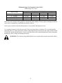
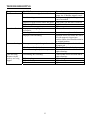
Minimum Gauge for Extension Cords (AWG)
(When using 120 V only)
Ampere Rating
0 – 6 Amps
6 – 10 Amps
10 – 12 Amps
12 – 16 Amps
Total Length of Cord in feet
50'
100'
150'
16 gauge
16 gauge
14 gauge
16 gauge
14 gauge
12 gauge
16 gauge
14 gauge
12 gauge
12 gauge
Not Recommended
25'
18 gauge
18 gauge
16 gauge
14 gauge
Make sure your extension cord is properly wired and in good condition. Always replace a damaged extension
cord or have it repaired by a qualified person before using it.
Protect your extension cords from sharp objects, excessive heat and damp/wet areas.
Use a separate electrical circuit for your tools. This circuit must not be less than a #12 wire and should be
protected with a 15 A time-delayed fuse. Before connecting the motor to the power line, make sure the switch
is in the OFF position and the electric current is rated the same as the current stamped on the motor nameplate.
Running at a lower voltage will damage the motor.
WARNING: This tool must be grounded while in use to protect the operator from electric shock.
8
KNOW YOUR BENCH GRINDER
6
5
7
4
3
8
2
1
1
2
3
4
5
6
9
10
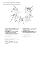
INNER WHEEL GUARD - Covers the
grinding wheels and protects against
accidental contact.
TOOL RESTS - Used to support the
workpiece that is being ground.
Adjustable to provide angled surfaces.
GRINDING WHEEL 120 GRIT - Used
to remove light material from workpiece.
EYESHIELD - Protective Lexan
see-thru shields to prevent any loose
debris from contacting the operator.
LOCKING KNOB-Lock the eyeshield
in position.
SPARK ARRESTOR - Prevents hot
sparks and debris from contacting the
operator.
7
8
9
WHEEL COVER - Covers the grinding
wheels and provides quick access for
routine maintenance.
GRINDING WHEEL 60 GRIT - Used to
remove light material from workpiece.
ON/OFF SWITCH - Used to turn the
grinder ON and OFF.
10 MOTOR HOUSING - Contains the
electrical motor.
9
ASSEMBLY
Warning: To avoid injury from unexpected starting or electrical shock, do not plug the power cord
into a source of power during unpacking and assembly. This cord must remain unplugged whenever
you are adjusting/assembling the grinder.
If any part is missing or damaged, do not attempt to assemble the grinder or plug in the power cord.
All of the parts needed for assembly should be located and accounted for before beginning.
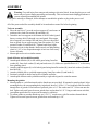
Tool rest assembly
1. Place the tool rest (C) over the tool rest support (G) and secure in
position with a 6mm flat washer (B) and knob (A).
2. Attach the tool rest support to the bottom of the left wheel guard.
Insert a carriage bolt (P) through cover and guard. Place upper
slot of support over carriage bolt and lower slot over the raised
boss on guard. Secure support using 5mm flat washer (F), 5mm
serrated washer (E) and knob (D). Tighten knob finger tight.
3. Position tool rest so that distance between tool rest and grinding
wheel is 1/16” or less. Reposition angle of tool rest if necessary.
Secure all knobs.
4. Mount right tool rest in a similar manner.
Spark deflector and eyeshield assembly
1. Attach spark deflector (N) to left wheel guard using 5mm flat
washer (K), 5mm lock washer (E) and pan head screw (O). Make sure spark deflector is ¼” or less away
from grinding wheel.
2. Attach eyeshield support (L) to left wheel guard using 6mm flat washer (B), 6mm lock washer (I) and hex
head bolt (H).
3. Attach eyeshield (M) to eyeshield support using 5mm flat washer (K) and knob (J).
4. Position eyeshield as desired and secure all knobs and bolts.
5. Attach spark deflector and eyeshield assembly to right wheel guard in a similar manner.
Mounting the grinder
1. Mount grinder to a solid horizontal surface (hardware not provided). If mounted to metal pedestal, align
mounting holes with corresponding holes in pedestal. Insert a 1/4-20 x 1¼” hex head bolt with flat washer
through base of grinder. From bottom of pedestal, place a 1/4” flat washer and 1/4”-20 hex nut onto the
bolt. Tighten only until space between grinder base and pedestal is 1/8”. Using second nut on each bolt,
jam tighten against the first to prevent loosening by vibration.
2. To mount grinder to wooden bench top, use 1/4 x 1¼” wood screws with flat washers beneath heads.
Tighten screws until space between grinder base and bench top is 1/8”.
10
OPERATION
Caution: Keep all bystanders a safe distance away from the tool and not in direct line, front or back
of the grinder.
1. To operate the bench grinder, always wear safety glasses and turn the tool on while standing at the side of
the grinder (as opposed to in front). Allow it to reach full speed before grinding.
2. Hold the work piece firmly against the tool rest. Hold very small pieces with pliers or other suitable
clamps.
3. Feed the work piece smoothly and evenly into the grinding wheel.
4. Move the work piece slowly and avoid jamming the work piece against the wheel. If the wheel tends to
slow down from excessive force, you should occasionally release the pressure to let the wheel return to
full speed.
5. Grind only on the face of the grinding wheel; never the side of it.
Caution: Prolonged grinding will cause most materials to become hot. Use care when handling
such materials.
SCISSORS
If possible, take the scissors apart to make the sharpening operation easier and safer. Remove material only
from the outside surface and work from the heavy end of the blade toward the tip.
KNIVES
Remove metal from both faces of most knives, working from the heavy end of the blade toward the tip.
SCREWDRIVERS
The end of a properly sharpened screwdriver will be a perfectly flat rectangle, perpendicular to the centerline
of the shank. The two sides and two faces will taper outward from the edge of the shoulder or shank. They
should be flat with perpendicular intersecting faces. Hold each face of the screwdriver against the wheel to
true it up, then ease the end straight into the stone to grind it true.
LAWN MOWER BLADES
Lawn mower blades are usually sharpened on only one side and dressed up slightly on the other. After
sharpening, be sure to balance the blade by removing additional material from the heavy end. There are a
number of inexpensive cone balancers on the market for this purpose. Unbalanced blades can cause serious
crank shaft damage to your lawn mower. Always remove spark plug wires from the mower before servicing
the blades to prevent accidental starting.
11
MAINTENANCE
Warning: For your own safety, turn switch to OFF and remove plug from power source outlet
before adjusting and maintaining your bench grinder. If power cord is worn, cut or damaged in any
way, have it replaced immediately.
1. Regularly check the tool and use a soft brush to remove accumulated dust. Wear safety goggles to protect
your eyes while cleaning.
2. If the body of the grinder needs cleaning, wipe it down with a soft, damp cloth. A mild detergent can be
used. Do not use alcohol, petrol or other similar cleaning agents. Do not make contact with the grinding
wheels with any damp cloth.
3. Always make sure the eye shields are transparent and not blocking the view of the grinding wheel.
4. In normal use, grinding wheels may become cracked, grooved, rounded at the edges, chipped, out of true
or loaded with foreign material. Cracked wheels should be replaced IMMEDIATELY. While any of the
other conditions can be remedied with a dressing tool (included), new wheels sometimes require dressing
to make them round.
5. If you must replace a wheel be sure to obtain one with a safe rated speed at least as high as the “NO
LOAD” RPM marked on your grinder’s nameplate. Replacement wheels must have a ½-inch center hole
and a 6-inch diameter with a maximum width of ¾ inch. Test new wheels for cracks and maintain the
existing sequence of retaining hardware. Be sure the tool is unplugged before attempting repairs.
Caution: Never use caustic agents to clean the plastic parts of the tool.
Caution: Water must never come into contact with the grinder.
Caution: The use of any other accessories is not recommended and may result in serious injury.
12
TROUBLESHOOTING
Symptom
Grinder won’t start
Possible Cause
Blown line fuse or tripped circuit breaker
Low line voltage
Excessive vibration
Motor overheating
Material wedged between wheel and guard
Defective switch
Defective, blown capacitor
Improper mounting of grinder or
accessories
Grinding wheel out of balance
Improper wheel mounting
Excess pressure required to grind material
Grinding on side of wheel
Motor not turning freely (without power)
Fuses are being
blown or circuit
breakers are being
tripped
Overloading due to binding
Defective plug
Defective cord
Defective switch
13
Corrective Action
If fuse is blown, replace with fuse of
proper size. If breaker tripped, reset it
Check power supply for voltage and
correct as needed
Turn grinder off and remove material
Replace switch
Replace capacitor
Remount
Dress wheels or replace wheels
Remount wheels, but rotate one wheel
90º with respect to its previous
position. Other wheel should remain in
its original position
Dress wheel or replace wheel with one
of proper grit
Grind only on face of wheel
Clean around wheels and shaft and/or
replace bearings
Clean around wheels and shaft and/or
replace bearings
Replace plug
Replace cord
Replace switch
EXPLODED VIEW
14
PARTS LIST
Item
1
2
3
4
5
6
7
8
9
10
11
12
13
14
15
16
17
18
19
20
21
22
23
24
25
26
27
28
29
Stock #
4286-001
4286-002
4286-003
4286-004
4286-005
4286-006
4286-007
4286-008
4286-009
4286-010
4286-011
4286-012
4286-013
4286-014
4286-015
4286-016
4286-017
4286-018
4286-019
4286-020
4286-021
4286-022
4286-023
4286-024
4286-025
4286-026
4286-027
4286-028
4286-029
Description
Screw
Bolt
Left guard cover
Nut
Flange
Grinding wheel 120#
Screw
Lock washer
Spark deflector
Flat washer
Left eyeshield (magnifier)
Left eyeshield support
Knob
Flat washer
Lock washer
Bolt
Left guard
Hex flange nut
Left toolrest support
Flat washer
Knob
Left tool rest
Knob
End shield
Washer
Stator
Grommet
Washer
Flat washer
Item
30
31
32
33
34
35
36
37
38
39
40
41
42
43
44
45
46
47
48
49
50
51
52
53
54
55
56
57
15
Stock #
4286-030
4286-031
4286-032
4286-033
4286-034
4286-035
4286-036
4286-037
4286-038
4286-039
4286-040
4286-041
4286-042
4286-043
4286-044
4286-045
4286-046
4286-047
4286-048
4286-049
4286-050
4286-051
4286-052
4286-053
4286-054
4286-055
4286-056
4286-057
Description
Lock washer
Screw
Switch
Screw
Switch plate
Lock washer
Bolt
Cover
Foot
Screw
Capacitor
Capacitor support
Nut
Ball bearing
Armature
Base
Strain relief plate
Strain relief
Power cord
Right eyeshield support
Right eyeshield
Screw
Right tool rest
Right toolrest support
Right guard
Grinding wheel 60#
Nut
Right guard cover
LIMITED TWO YEARS WARRANTY
WEN Products is committed to build tools that are dependable for years. Our warranties are consistent with this commitment and our dedication
to quality.
LIMITED WARRANTY OF WEN CONSUMER POWER TOOLS PRODUCTS FOR HOME USE
GREAT LAKES TECHNOLOGIES, LLC ("Seller") warrants to the original purchaser only, that all WEN consumer power tools will be free
from defects in material or workmanship for a period of two (2) years from date of purchase. Ninety days for all WEN products, if the tool is used
for professional use.
SELLER'S SOLE OBLIGATION AND YOUR EXCLUSIVE REMEDY under this Limited Warranty and, to the extent permitted by law, any
warranty or condition implied by law, shall be the repair or replacement of parts, without charge, which are defective in material or workmanship
and which have not been misused, carelessly handled, or misrepaired by persons other than Seller or Authorized Service Center. To make a claim
under this Limited Warranty, please contact us at 1-800-232-1195. To acquire service, you will have to provide proof of purchase and may be
asked to ship the tool back to us freight prepaid.
THIS LIMITED WARRANTY DOES NOT APPLY TO ACCESSORY ITEMS SUCH AS CIRCULAR SAW BLADES, DRILL BITS,
ROUTER BITS, JIGSAW BLADES, SANDING BELTS, GRINDING WHEELS AND OTHER RELATED ITEMS.
ANY IMPLIED WARRANTIES SHALL BE LIMITED IN DURATION TO ONE (1) YEAR FROM DATE OF PURCHASE. SOME STATES
IN THE U.S., SOME CANADIAN PROVINCES DO NOT ALLOW LIMITATIONS ON HOW LONG AN IMPLIED WARRANTY LASTS,
SO THE ABOVE LIMITATION MAY NOT APPLY TO YOU.
IN NO EVENT SHALL SELLER BE LIABLE FOR ANY INCIDENTAL OR CONSEQUENTIAL DAMAGES (INCLUDING BUT NOT
LIMITED TO LIABILITY FOR LOSS OF PROFITS) ARISING FROM THE SALE OR USE OF THIS PRODUCT. SOME STATES IN THE
U.S. AND SOME CANADIAN PROVINCES DO NOT ALLOW THE EXCLUSION OR LIMITATION OF INCIDENTAL OR
CONSEQUENTIAL DAMAGES, SO THE ABOVE LIMITATION OR EXCLUSION MAY NOT APPLY TO YOU.
THIS LIMITED WARRANTY GIVES YOU SPECIFIC LEGAL RIGHTS, AND YOU MAY ALSO HAVE OTHER RIGHTS WHICH VARY
FROM STATE TO STATE IN THE U.S., PROVINCE TO PROVINCE IN CANADA AND FROM COUNTRY TO COUNTRY.
THIS LIMITED WARRANTY APPLIES ONLY TO PORTABLE ELECTRIC TOOLS, BENCH POWER TOOLS, OUTDOOR POWER
EQUIPMENT AND PNUMATIC TOOLS SOLD WITHIN THE UNITED STATES OF AMERICA, CANADA AND THE
COMMONWEALTH OF PUERTO RICO. FOR WARRANTY COVERAGE WITHIN OTHER COUNTRIES, CONTACT THE WEN
CUSTOMER SUPPORT.
16