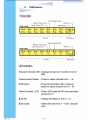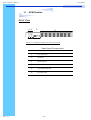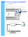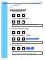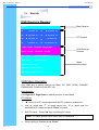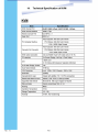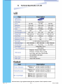
1
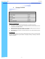
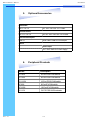
RKP115 / RKP117 / RKP119
User Manual
4.
Package Contents
LCD Monitor Drawer with IP KVM Switch
1 Piece
User Manual
1 Piece
DC Power Adapter
1 Piece
Power Cord
1 Piece
Mounting Bracket
1 Pair
Fasteners
4 Pieces
CD-6 3-in-1 KVM cable
8 Pieces
Before Unpacking
It is very important to locate the LCD Keyboard Drawer in a suitable environment.
●
The surface for placing and fixing the LCD Keyboard Drawer should be stable and level
or mounted into a suitable cabinet.
●
Make sure the place has good ventilation, is out of direct sunlight, away from sources of
excessive dust, dirt, heat, water, moisture and vibration.
●
Convenience for connecting the LCD Keyboard Drawer to the related facilities should be
well considers too.
Unpacking
The LCD Keyboard Drawer comes with the standard parts shown as above. Check and make
sure they are included and in good condition. If anything is missing, or damage, contact the
supplier immediately.
Rev. : 1.0
P.3
RKP115 / RKP117 / RKP119
User Manual
5.
Optional Accessories
KVM Cable
CD-6 / 10 / 15
6ft / 10ft / 15ft PS/2 3-in-1 cable
Cascade Cable
CA-2 / 6 / 10 / 15
2ft / 6ft / 10ft / 15ft PS/2 3-to-3 cable
Conversion Adapter
SUN-31
SUN / iMAC USB to PS/2 adapter
Others
Video Input
12V / 24V / 48V DC Power Supply
Rev. : 1.0
6.
Peripheral Products
Model
Description
CV-401
4-Port PS/2 KVM switch
CV-801
8-Port PS/2 KVM switch
CV-1601
16-Port PS/2 KVM switch
IP-802
8-Port IP KVM switch
IP-1602
16-Port IP KVM switch
CV-101
CAT.5 PS/2 KVM extender
P.4
RKP115 / RKP117 / RKP119
User Manual
7.
Important Safeguards
Please read all of these instructions carefully before you use the device.
Save this manual for future reference.
●
Unplug the LCD Keyboard Drawer from the power outlet before cleaning.
●
Do not spray liquid cleaners or aerosol directly on the device. Wet a cloth with a
neutral detergent (e.g. clean water) and squeeze it tight, then clean the screen
slightly with it.
●
Do not expose the LCD Keyboard Drawer directly to rain, water, moisture or
sunlight.
●
Avoid pressure on the LCD screen to prevent permanent damage to the display.
●
Do not attempt to service the device yourself. Improper operation may void your
warranty. Refer all servicing to qualified service personnel.
●
●
Safe storage environment of the LCD Keyboard Drawer is ranging between –20oC
and 60oC. Permanent damage could occur if the LCD Keyboard Drawer is stored
outside the safe range.
Unplug the LCD Keyboard Drawer immediately and call qualified service
personnel under the following conditions:
1.
If the monitor has been exposed to rain, liquid or water.
2.
If the monitor has been dropped or the casing has been damaged.
What the warranty does not cover
1.
Any product, on which the serial number has been defaced, modified or
removed.
2.
Damage, deterioration or malfunction resulting from:
a) Accident, misuse, neglect, fire, water, lightning, or other acts of nature,
unauthorized product modification, or failure to follow instructions supplied
with the product.
b) Repair or attempted repair by anyone not authorized by us.
c) Any damage of the product due to shipment.
d) Removal or installation of the product.
e) Causes external to the product, such as electric power fluctuation or failure.
f) Use of supplies or parts not meeting our specifications.
g) Normal wear and tear.
h) Any other causes which does not relate to a product defect.
3.
Rev. : 1.0
Removal, installation, and set-up service charges.
P.5
RKP115 / RKP117 / RKP119
User Manual
8.
Structure Diagram
1.
PS/2 keyboard
2.
Aluminium front panel
3.
Class A active matrix TFT LCD panel
4.
Rear metal case
5.
LCD inverter
6.
LCD membrane
7.
Ball bearing telescopic slides with stopper
8.
Adjustable mounting bracket
9.
Optional KVM switch
•
‚ ƒ „
†
Rev. : 1.0
‰ ‡
P.6
…
‰
ˆ
RKP115 / RKP117 / RKP119
User Manual
LCD
Session
Rev. : 1.0
P.10
RKP115 / RKP117 / RKP119
User Manual
10.
LCD Session
LCD Membrane Diagram
Power
Menu/Selection
Right
Left
Exit
MAIN MENU
BRIGHT/CONTRAST
AUTO ADJUST
PHASE/CLOCK
H/V POSITION
MISC
RESET
Main Menu
Bright / Contrast
●
To enter into the Bright, Black level & Contrast sub-menu
Auto Adjust
●
To perform automatic optimisations of all functions
●
An “ Adjusting” message is displayed during the process
Phase / Clock
●
To enter into the phase & clock sub menu
H/V Position
●
To enter into the H/VPosition sub-menu
MISC
●
To enter into the MISC sub-menu
Reset
● Reset to the default factory settings
Rev. : 1.0
P.11
RKP115 / RKP117 / RKP119
User Manual
10.
LCD Session
Bright / Contrast
1. Brightness
●
To perform brightness adjustment of the input RGB signal
●
Use the Left & Right button to adjust and button
to “Brightness”
2. Contrast
●
To adjust the contrast level of the input signal
●
Use the Left & Right button to adjust and button
to “Contrast”
Phase / Clock
1. Phase
●
To adjust input video sampling clock’s phase
●
Use the Left & Right button to adjust and button
to “Phase”
2. Clock
●
To adjust input video sampling clock
●
Use the Left & Right button to adjust and button
to “Clock”
H/V Position
1. H.Position
●
To adjust the horizontal size of the frame
●
Use the Left & Right button to adjust and button
to “H.position”.
2. V.Position
Rev. : 1.0
●
To adjust the vertical position of the frame
●
Use the Left & Right button to adjust and button
P.12
to “V.position”.
RKP115 / RKP117 / RKP119
User Manual
10.
LCD Session
MISC
1. Information
●
●
●
The first header row shows the current resolution setup
The second header row shows the horizontal frequency of the current
input signal
The third header row shows the vertical frequency of the current input
signal
2. OSD Timer
●
To modify the duration of the OSD time-out
3. Color
a) 5500K
●
Select Colour Temp at 5500K
b) 6500K
●
Select Colour Temp at 6500K
c) 9500K
●
Select Colour Temp at 9500K
d) User
●
Change Colour Temp by manual
4. Language
● To select the language of OSD menu 7 Languages :
(1) English
(2) Japanese (日本語)
(3) Chinese (中文)
(4) German
(5) Francais
(6) Espanol
(7) Italiano
Rev. : 1.0
P.13
RKP115 / RKP117 / RKP119
User Manual
10.
LCD Session
Resolution Settings
For Microsoft Windows
Step 1 – Press right click on the desktop
Step 2 – Choose “Properties”
Step 3 – Change the “Screen Resolution”
Step 4 – Change the “Screen refresh rate”
Rev. : 1.0
P.14
RKP115 / RKP117 / RKP119
User Manual
10.
LCD Session
Resolution Settings
For SUN Servers
●
●
●
●
●
●
●
●
Resolution configuration procedures should be run by qualified SUN
server administrator
Sun Servers are using resolution at 1152 x 900 x 76Hz.
Supported resolution mode for 15” LCD:
1024 x 768 x 70/75Hz
Supported resolution mode for 17” LCD:
1280 x 1024 x 75Hz
You need to change the Sun Server resolution before you connect to
LCD Display.
Please do the following procedures to change the resolution settings :
1. As root:
You may find the following comment “/user/sbin/m64config”.
2. To view current resolution:
Type “/user/sbin/m64config – prconf”.
3. To change to 1024x768 @ 70MHz:
Type “/user/sbin/m64config – res 1024x768x70 now”.
4. The screen will be rubbish.
5. Then type “pkill Xsun”.
And Type “pkill Xsession” to restart the Xsession.
Note : Remember to RESTART the server after these processes.
●
Under Common Desktop Environment (CDE).
●
To change the OpenBoot resolution, you can type the following
command in OK prompt.
1. In OK prompt, type “setenv output-device screen:r1024x768x70”.
2. Type “printenv” to confirm the resolution has been changed
to 1024x768x70Hz.
3. Then type, “reset” to restart the system.
Note : Remember to RESTART the server after these processes.
Rev. : 1.0
P.15
RKP115 / RKP117 / RKP119
User Manual
KVM
Session
Rev. : 1.0
P.16
RKP115 / RKP117 / RKP119
User Manual
11.
KVM Session
Rear View
lk
k
o n
m
j
Figure 11-1. Identifying IP KVM rear panel components
Rear Panel Components
Location
Rev. : 1.0
Component
j
8 or 16 PC Ports
k
Serial Port
l
RJ-45 LAN Port
m
Cascade Port
n
Virtual Media USB Port
o
DC Power Input
P.18
RKP115 / RKP117 / RKP119
User Manual
11.
KVM Session
Step 4. Connect the IP KVM to your Servers using the provided KVM cables* (Fig. 1)
VGA HDDB-15-pin connector on KVM cable (Blue)
PS/2 mouse connector on KVM cable (Green)
PS/2 keyboard connector on KVM cable (Purple)
Figure 11-4. PS/2 KVM Cable
Server connectors
PS/2 keyboard port of your server
PS/2 mouse port of your server
VGA HDDB 15-pin display output port of your server
Step 5. Connect IP KVM to the network for remote control purpose.
Remote site: Using Java Enabled Browser to remote access and mange your servers.
Internet / Intranet Network
Figure 11-5. IP KVM Rear View
**Refer to the IP KVM user manual for detail setup and usage.
Rev. : 1.0
P.20
RKP115 / RKP117 / RKP119
User Manual
11.
KVM Session
Cascading
Using CA-6 PS/2 KVM cable to connect from Bank 1’s “Cascade port” to
Bank 2’s “Console port”. After connected please press “Bank” & “Channel”
button on the front of the PS/2 KVM switch to reset the PS/2 KVM switch.
Bank 1
Figure 11-6. IP KVM Rear View
Bank 2
Bank 8
(Max.)
CA-6 PS/2 KVM cable
Figure 11-7. PS/2 KVM Rear View
CA-6 PS/2 KVM cable
Figure 11-8. PS/2 KVM Rear View
Cascade level Max. : 8 level
Rev. : 1.0
●
Max. PC connection is 128 or with additional 122 PCs.
●
All PS/2 KVM switch is compatible & can cascade with each other.
●
Using CA-6 PS/2 KVM cable to cascade.
●
Normal distance from one PS/2 KVM to another is 15 feet.
P.21
RKP115 / RKP117 / RKP119
User Manual
11.
KVM Session
Remote Access the IP KVM
Device Factory Default Information:
IP Address : 192.168.1.22
Subnet mask: 255.255.255.0
Gateway
: none
Login name : super
Passwords : pass
Step 1. Open your java enabled browser, e.g.: Internet Explorer 6, Netscape,
Mozilla, FirFox..
Step 2. Enter the IP address of the IP KVM in the address box.
http://192.168.1.22
Enter Username “super”
(Factory default)
Enter Password “pass”
(Factory default)
Figure 11-9. IP KVM login page
*All brand names, logo registered trademarks are properties of their respective owners.
*All information change without any notice
Rev. : 1.0
P.22
RKP115 / RKP117 / RKP119
User Manual
11.
KVM Session
IP KVM web base interface
j
k
l
m
n
o
p
q
Figure 11-10. Main page of IP KVM
IP KVM Configurations
Location
Function
j
KVM Console & Telnet Console setup
k
Virtual Media setup
l
Change Password and User management
m
User Console, Keyboard, mouse and Video settings
n
Network, Serial port, security, date, log view settings
o
Device Status, Firmware upgrade, Event log & Unit reset
p
Log off user and exit from IP KVM.
q
Current console preview
**Refer to the IP KVM user manual for detail setup and usage.
*All brand names, logo registered trademarks are properties of their respective owners.
*All information change without any notice
Rev. : 1.0
P.23
RKP115 / RKP117 / RKP119
User Manual
12.
Start Up
1.
The channels that have PC connected and it is switch on will have a
green LED on that channel.
2.
The red LED will indicate the selected channel.
3.
7 segments LED will display the bank number.
4.
Press channel button to select the channel.
5.
Enter the password, default is “00000000” eight zeros.
6.
Otherwise the keyboard & mouse will be locked.
7.
If you forget your password, send back to Manufacturer.
HotKey Command
Rev. : 1.0
●
Simple key sequence.
●
Press “ Scroll Lock” twice within 2 seconds.
●
Follow with a beep sound, going into the hot key mode.
●
Need to key in the hot key within 2 seconds.
●
Go back to Operation System Control state.
P.24
RKP115 / RKP117 / RKP119
User Manual
12.
Start Up
Hot-key Command Operation
1.
Calling OSD Menu
Scroll
2.
Space Bar
Scroll
+
£
+
Switch to Next Power On Port (powered on PC only)
Scroll
4.
+
Switch to Previous Port (powered on PC only)
Scroll
3.
Scroll
+
Scroll
+
¤
+
Switch to Previous Bank
Scroll
Scroll
+
First digit of Port Number:
0 for Port 0-9
1 for Port 10-16
Pg
Up
+
Second digit of
port Number
5.
Switch to Specific Port
Scroll
Scroll
+
Bank
1~8
+
No.
0 or 1
+
No.
0-9
+
Example :
a)
Bank 1 Port 4
Scroll
b)
Scroll
+
1
+
0
2
+
1
+
4
Bank 2 Port 16
Scroll
Rev. : 1.0
+
+
Scroll
+
P.25
+
6
RKP115 / RKP117 / RKP119
User Manual
12.
Start Up
HotKey Command Operation
6.
Switch to Next Bank
Scroll
7.
+
Scroll
+
PgDn
Enable / Disable beeper sound
Scroll
+
Scroll
B
+
Note: The default Beeper function is ON and beeper control is only for
8.
Auto Scan for Powered on PC
Scroll
9.
+
Scroll
S
+
Reset to factory Default Setting
Scroll
+
Scroll
R
+
ROM REFLASH
Note: Not available for password reset.
10. Find Port by name
Scroll
+
Scroll
F
+
FIND:█
Note: When the above dialogue appear, type the PC name and the OSD Menu
will search PC name starting from 1st powered on PC port.
Rev. : 1.0
P.26
RKP115 / RKP117 / RKP119
User Manual
12.
Start Up
OSD Structure Diagram
Bank Session
BANK : 1
BANK : 1 SYSTEM 01
01
01
03
SYSTEM
01 03
®
SYSTEM
03
05
03
® SYSTEM 05
05
07
® SYSTEM 05
07
02
® SYSTEM 02
E
SYSTEM0204
02 ®®SYSTEM
04
06
06
08
® SYSTEM
SYSTEM0406
PC Session
SYSTEM
06 08
®
SYSTEM
07
® SYSTEM 08
OSD SYSTEM
: 1 0 SEC. 07
CHANGE08PASSWORD
OSD : 1 0 SEC. CHANGE
SCAN:
CONSOLEPASSWORD
ON/OFF
KVM Settings
Session
SCAN:
1 0 SEC. ENTER
CONSOLE
ON/OFF
ESC
: QUIT
:COMPLETE
ESC :: QUIT
TAB
NEXT
ENTER
:COMPLETE
INSERT
:EDIT
Menu
Information
TABSELECT
: NEXT PORT
INSERT :EDIT
á/â:
á/â: SELECTBANK
PORTSELECT
PgDn/PgUp:
PgDn/PgUp: BANK SELECT
OSD Menu Operation
Use “Tab” key to select session like Bank, PC, OSD, SCAN, CHANGE
PASSWORD, CONSOLE ON/OFF, etc…
Bank Session
Use Page Up & Page Down to switch previous or next bank
PC Session
1.
“®” next to the PC name represents the PC system is powered on
2.
Use up arrow key “á” or down arrow key “â” to select port for
destination PC name and press “Enter” to select
3.
Edit PC name - Press “Ins” key for editing PC name
Note: PC name should not be more than 8 characters.
4.
Rev. : 1.0
When editing is finished press “Enter”.
P.27
RKP115 / RKP117 / RKP119
User Manual
12.
Start Up
KVM Settings Session
1.
OSD
●
●
2.
●
It can be modified to 99
seconds for maximum.
Choose “Change Password” in
KVM Setting Session.
●
Key-in the existing password.
●
Enter the New Password.
●
Re-Enter the New Password.
●
Changing Password complete.
●
The steps are shown as next
picture:
Console On/OFF
●
ON – any user can use the
console
●
●
5.
Scan interval from one PC port
to next PC port when applying
auto scan, its default is 10
seconds.
Change Password
●
Default password “00000000”
8 zeros
●
4.
It can be modified from 05 – 99
seconds.
Scan
●
3.
OSD Menu on screen time
default is 10 seconds.
OFF – user is not allowed to
use the console port, unless
password is entered.
Default – OFF, you need to
key-in password.
Escape
When the following screen is
appeared, you can press
”ESC” key to escape.
ENTER PASSWORD : █
ESC : QUIT
ENTER :
ENTER NEW PASSWORD : █
ESC : QUIT ENTER : COMPLETE
RETYPE NEW PASSWORD : █
ESC : QUIT ENTER :
COMPLETE
NEW PASSWORD COMPLETE
ESC : QUIT ENTER :
COMPLETE
●
Rev. : 1.0
P.28
102
?SYSTEM 02
RKP115 / RKP117 / RKP119
User Manual
13. FAQ
1. Don’t press any keys on the keyboard while the selected
computer is booting up. Otherwise, it might cause the
keyboard error or keyboard is not detected at PC side.
2. The computer boot up fine, but keyboard doesn’t work.
●
Make sure the keyboard works when directly plugged into the computer.
●
Try a different keyboard, but use only 101, 102 or 104-key keyboard.
3. The Mouse is not detected during PC boot up.
●
Make sure the mouse works when directly plugged into the computer.
●
Make sure the mouse is a true PS/2 mouse. A combo mouse will work just as long
as it is set for PS/2 mode with the correct adapter. Try a different mouse.
Avoid moving the mouse or pressing the mouse buttons when switching ports.
Avoiding switching ports during shutting down the PC process.
●
●
●
When you switch one PC port to another PC port, the best scan time setting need to
be set to 5 seconds or more. Normally, the VGA monitor change one resolution
mode to another will take one or two seconds. So, the scan time is not
recommended to below 5 seconds.
4. Sun Server connection problem.
PS/2 KVM switch are using standard PS/2 type keyboard, mouse and D-sub 15pin
VGA for connection. If you need to connect Sun Server to PS/2 KVM switch, you need
a separate converter kit.
5. Sun – 31 Kit
●
●
Rev. : 1.0
Convert USB to P/S 2 Keyboard & Mouse.
New model Sun Micro Server are using D-sub 15 pin Standard VGA.
P.29