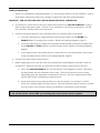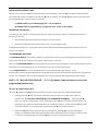
1
Installation and Operating Manual Advantage DK ADV-1000 ADV-1000i (intercom) Digital Access Control Station American Access Systems, Inc. 7079 South Jordan Road, #6 Centennial, CO 80112 800.541.5677 www.americanaccess.com Table of Contents WARRANTY ...................................................................................................................................................................... 3 PARTS CHECKLIST ............................................................................................................................................................. 4 TOOLS NEEDED FOR BASIC INSTALLATION................................................................................................................... 4 WIRING DIAGRAMS......................................................................................................................................................... 5 INTRODUCTION ................................................................................................................................................................ 6 BEFORE INSTALLATION .................................................................................................................................................... 6 MOUNTING THE UNIT ....................................................................................................................................................... 7 SYSTEM CONNECTIONS .................................................................................................................................................. 7 HARNESS COLOR CODES ............................................................................................................................................... 8 WIRING CONNECTIONS.................................................................................................................................................. 9 THE IDLE MODE ...............................................................................................................................................................10 ACCESS CODES AND FUNCTION CODES...................................................................................................................10 GOOD TONES AND ERROR TONES ..............................................................................................................................11 PROGRAMMING THE DK UNIT ......................................................................................................................................12 Program Relay A Access Codes -- Sub-Mode 1 ...............................................................................................13 Delete Individual Access Codes -- Sub-Mode 2 ...............................................................................................14 Change the Master Code -- Sub-Mode 3 ...........................................................................................................14 Set Sleep Code -- Sub-Mode 4 .............................................................................................................................15 Set Latch Code -- Sub-Mode 5..............................................................................................................................16 Set Relay Output Times -- Sub-Mode 6 ................................................................................................................16 Program Relay B Access Codes -- Sub-Mode 7 ................................................................................................16 Enable or Disable the “Three Strikes … You’re Out” Sub-Mode 8...................................................................17 Event Input -- Sub-Mode 9 .....................................................................................................................................18 Erase All Codes -- Sub-Mode 0 .............................................................................................................................19 RESETTING THE DK UNIT .................................................................................................................................................20 Master Reset ..............................................................................................................................................................20 Unit Reset....................................................................................................................................................................20 TROUBLESHOOTING .......................................................................................................................................................23 Page 2 © American Access Systems Two-Year Limited Warranty This Warranty applies to: American Access Systems “Advantage DK” access controls What is Covered: Any defects in materials or workmanship Coverage Period: Two years from date of purchase What We Will Do: If your American Access Systems, Inc. (AAS) product is defective and returned within two years of purchase, well will repair, or at our option, replace the unit at no charge to you. If we repair your AAS Product, we may use new or reconditioned parts. If we choose to replace your AAS product, we may replace it with a new or reconditioned unit of the same or similar design. The repair or replacement unit is warranted for (a) Ninety days (b) the remainder of the original two-year warranty period, whichever is longer. Limitations: Implied warranties, including those of fitness for a particular purpose and merchant ability (an unwritten warranty that the product is fit for ordinary use,) are limited to two years from the date of purchase. AAS will not pay for loss of time, inconvenience, loss of use of your AAS product, service calls, or property damage caused by your AAS product or its failure to operate, or any other incidental or consequential damages. Some States do not allow limitations on how long an implied warranty lasts or the exclusion or limitation of incidental or consequential damages, so the above exclusions or limitations may not apply to you. What We Ask You To Do: To receive warranty service for your AAS product, you must provide proof of the date of purchase. Contact the original dealer or installer of the product and return your AAS product along with the receipt to them. If you have problems locating the dealer or installer, contact American Access Systems at (303) 799-9757, and we will direct you to an AAS authorized dealer or distributor. If you ship your AAS product, you must prepay all shipping charges. We suggest that you retain your original packing material in the event you need to ship your AAS product. Upon return, include your name, address, phone number, proof of date of purchase, and a brief description of the operating system problem. This information needs to be included to receive an AAS “RMA” number. What This Warranty Does Not Cover: The warranty does not cover defects resulting from accidents, damage while in transit, alterations, unauthorized repair, failure to follow installation and operating instructions, misuse, fire, flood, or acts of God. Nor do we warrant your AAS product to be compatible with any particular external device or peripheral. If your Warranty has expired on your AAS product, or if your product is NOT covered, contact your dealer or installer for advice on whether we will repair your AAS product and other repair information, including estimated repair costs and additional charges that may be incurred. We, at our option, may replace, rather than repair your AAS product with a new or similar design if the damage to the unit is severe or extensive. This is the only Warranty we offer on this product, and it sets forth all of our responsibilities regarding your AAS product. There are no other express Warranties. State Law Rights: This Warranty gives you specific legal rights, and you may also have other rights which vary from State to State. American Access Systems, Inc. 7079 South Jordan Road - Unit 6 Centennial, CO 80112 (303) 799-9757 Page 3 © American Access Systems PARTS CHECKLIST Parts that are included in the box include the following items. If any of the items is missing, contact American Access Systems (AAS). QTY Item 1 Advantage DK Control Station (w/2 keys) 4 ¼”-20 X ½” carriage bolts 4 ¼”-20 hex nuts TOOLS NEEDED FOR BASIC INSTALLATION ; Wire nuts or appropriate terminals/connectors ; Wire strippers ; Wire cutters ; 3/8” drive ratchet, 6” extension, 7/16” socket ; Digital or Analog multi-meter Technical/Customer Support 1-303-799-9757 or [email protected] Page 4 © American Access Systems Page 5 © American Access Systems INTRODUCTION The American Access Systems (AAS) Advantage DK unit is a high-quality, user-programmable, commercial-duty digital key control station designed to control access to a passageway using 4-digit access codes. The Advantage DK integrates state-of-the-art electronics resulting in a product which is highly sophisticated, yet inexpensive. The Advantage DK unit features: 1 programmable 4-digit Master Code. (Factory default is 1 2 5 1 … it is recommended that you re-program to a personal master code of your choice.) 1 programmable 4-digit Sleep Code 1 programmable 4-digit Latch Code Master user ability to program up to 1000, 4-digit access codes which can be assigned to 1 of 2 relays A programmable “Three Strikes You’re Out” feature which disables the unit for approximately 90 seconds if three incorrect Access Codes are entered during a 90-second time period Two relays programmable from ½ to 99 seconds incorporating both normally open (N/O) and normally closed (N/C) contacts. An external event trigger, programmable as a Remote Inactive, Arming, or Remote Open input. BEFORE INSTALLATION To take full advantage of the 24 month limited warranty, you must register with American Access Systems, Inc. Please read and review the Warranty (page 3), complete the enclosed Warranty Registration card and send it to: American Access Systems, Inc. Warranty Registration 7079 South Jordan Road / Unit 6 Centennial, Co. 80155 Page 6 © American Access Systems INSTALLATION MOUNTING THE UNIT The tools and instruments needed to install your unit and a Parts Checklist are shown on page 4. Make sure you have all the tools listed before you begin. It’s a good idea to make sure to check off the items enclosed with the unit. If any parts are missing from the package, contact American Access Systems immediately. Mounting the unit to an AAS gooseneck pedestal (18-001) or double height gooseneck (18-003) Locate the four carriage bolts and four hex nuts found inside the shipping box. With the keypad face open, place the unit against the pedestal flange, insert the four carriage bolts from the back of the unit and tighten the hex nuts from the inside. Wrench tighten the hex nuts securely. Do not over tighten. SYSTEM CONNECTIONS An Operator Wiring Diagram and a Door Strike/Mag Lock wiring diagram for the Advantage DK are shown on page 5. The most common installation connects the DK unit to a Gate Operator only. Refer to the Operator Wiring Diagram (the top drawing.) If the DK unit is being connected to other devices and equipment, such as a door strike or mag lock, use the Door Strike/Mag Lock Wiring Diagram (the lower drawing.) Carefully study the diagram that best suits the installation conditions. The following is a key to the wire harness color codes. Page 7 © American Access Systems HARNESS COLOR CODES WHITE (AC Hot) (DC +) 11.5 - 29 volts AC or DC WHITE (AC Neutral)(DC -) 11.5 - 29 volts AC or DC GREEN EARTH GROUND ONLY RELAY A (PRIMARY) CONTROL COLOR CODES BROWN RELAY (A) COMMON ORANGE RELAY (A) NORMALLY OPEN (N/O) BLUE RELAY (A) NORMALLY CLOSED (N/C) RELAY B (SECONDARY) CONTROL COLOR CODES (Use if controlling a second device) RELAY (B) COMMON GRAY VIOLET RELAY (B) NORMALLY OPEN (N/O) YELLOW RELAY (B) NORMALLY CLOSED (N/C) Page 8 © American Access Systems WIRING CONNECTIONS 1. The DK unit is designed to operate between 11.5 volts minimum and 29 volts AC maximum. Using a multi-meter, measure the supply line voltage to make sure it falls within these tolerances. IMPORTANT: TURN OFF THE POWER SUPPLY BEFORE MAKING ELECTRICAL CONNECTIONS 2. Locate the two white wires on the circuit board main harness and, WITH THE POWER OFF, connect them to the power supply leads. Use wire nuts or connectors to secure the connections. The DK unit is rectified. Polarity need not be observed. 3. Connect the primary device to be controlled to the unit’s primary relay control leads. a. If you are connecting to a gate operator or electric door strike, use the BROWN and ORANGE leads for normally open contact. (Refer to the Wiring Diagrams, page 5.) b. If you are connecting to a mag-lock or any device that requires power in the locked state, use the BROWN and BLUE leads for normally closed contact. (Refer to the Wiring Diagrams, page 5.) c. If you interface with a secondary device, connect the unit’s secondary relay control leads to the secondary device. (Refer to the Wiring Diagrams, page 5.) 4. Connect the Green lead to Earth Ground. 5. Before supplying power to the unit, refer to the appropriate wiring diagram to double- check all connections. When you are sure you have the unit wired correctly, apply power to the unit. a. If this is the FIRST TIME POWER UP, the unit will perform a self-diagnostics routine. After each test has passed, the unit will respond with a tone. The unit will perform a total of 4 tests (depending upon the equipment connected to the unit.) The unit will then flash the LED's several times while it is performing a memory setup. b. Once all the tests have passed and the unit is set up correctly, you will hear a “GOOD TONE” (an oscillating high tone) from the unit. If the unit does not perform as above, quickly shut off power to the unit and contact your distributor or American Access Systems. NOTE: The unit will perform a self-diagnostics routine only during first-time power up. After first-time power up, the unit will sound a “GOOD TONE” (an oscillating high tone) each time power is applied. Page 9 © American Access Systems THE IDLE MODE When the desired connections are complete and power is supplied to the unit, the unit will be in the IDLE MODE. The IDLE MODE is the normal mode of operation, meaning the unit is ready to accept input from the keypad. When in the IDLE MODE, you have approximately 4 seconds between key presses. If this time is exceeded, you will receive an ERROR TONE. Any time you hear an ERROR TONE, simply begin whatever operation you were attempting over again. ACCESS CODES AND FUNCTION CODES There are two types of codes you need to keep in mind when using the Advantage DK unit. Access Codes, quite simply, are the numbers that are programmed into the unit and assigned to the users who need to access the gate or door. The Access Codes are the “everyday” use codes. Up to 1000 Access Codes can be programmed into the unit. Function Codes, on the other hand, are special modes that only the Master User or Administrator can enter to control how the DK unit is programmed and operates. There are 3 specialized Function Codes which are shown on the following Chart. MASTER The Master Code is a four-digit Function Code used to program Access Codes into CODE the DK unit. The factory default master code is 1 2 5 1. The Owner/Administrator enters the Master Code to program the Access Codes others will use to gain entry to the area controlled by the unit. It is recommended that the Master Code be re-programmed to a four-digit code of your choice. Remember to make a note of the new Master Code. It is the password to the unit and should be treated as confidential. LATCH The Latch Code is a programmable four digit Function Code used to toggle relay CODE A. The Latch Code is used to hold a gate or door open. For example, the home owner or business administrator wants leave the gate open for a period of time; say for a few hours during a party or special function. While the Latch Code is entered, the gate or door is open. Re-enter the Latch Code to return the unit to normal operation (to close and lock the gate or doorway.) SLEEP The Sleep Code is a programmable four digit Function Code which, when CODE entered, disables all codes. No one can use any of the Access Codes while the unit is in the SLEEP mode. An example is if the user wants to deny all access to a gated area for a period of time, he or she enters the SLEEP CODE which essentially locks the unit. Re-enter the Sleep Code to return the unit to normal operation. An override code is provided. Page 10 © American Access Systems GOOD TONES and ERROR TONES The DK unit sounds an audible tone each time a key is pressed. The star (Å) key serves as the clear key and a double tone is sounded when the star (Å) key is pressed. The pound (#) key is the exit key and exits the programming mode any time it is pressed. A "GOOD TONE" is an oscillating high tone. It is very distinct. An "ERROR TONE" is represented by a single low tone. It also is very distinct. THE RED AND YELLOW LEDs One Red (on the top left of the keypad) and one Yellow (on the top right of the keypad) LED are on the face of the unit. The red LED illuminates during the relay(s) activation period. The yellow LED illuminates anytime the unit is in the program mode. During memory erasure or during the setup routine, Both LEDs will flash repeatedly until the routine or erasure is complete. PROGRAMMING THE DK UNIT The PROGRAM MODE is used enter, delete, or change the codes or to set (energize) specific features of the unit or how the DK unit interacts with other components in a system. Access the PROGRAM MODE by entering the Master Code using the keypad. If the correct Master Code is entered the unit will reply with a GOOD TONE and the Yellow LED will illuminate. In the Program Mode you have approximately 30 seconds between key presses. If the 30-second time period is exceeded during programming, the unit will automatically exit the Programming Mode. No damage is done to the programming. Simply complete the programming steps again. NOTE: 1 2 5 1 WILL NOT OPEN THE GATE. 1 2 5 1 is the Master Code and allows access to the programming functions only. The Star (Å) and Pound (#) Keys The star (Å) and pound (#) keys serve specific functions while in the IDLE or PROGRAM mode. Pressing the star (Å) key will always clear the entry and emits a double tone when it is pressed. FIX : IF YOU’VE HIT THE FORTH KEY IS IT COMMITTED TO MEMORY. Press the star (Å) key if you want to delete entry. Note: Pressing the star (Å) key will erase an entire entry. For example, if you enter 4 5 and realize that you wanted to enter 5 4, press the star (Å) key and 4 5 will be erased. It is not necessary to press the star (Å) more than one time. The pound (#) key serves as the programming exit key. Pressing (#) will exit the program mode. For example, enter the programming mode, enter the Access Codes you wish to add to memory, and then press the pound (#) key to exit the programming mode. Page 11 © American Access Systems PROGRAMMING THE DK UNIT To access the program mode, enter the MASTER CODE. When the correct MASTER CODE is entered the yellow LED will light and a GOOD TONE will sound. You can now enter any of ten programming SUB MODES described below. SUB MODE NUMBER CODE DESCRIPTION 1 Program an Access Code(s) (Relay A) 2 Delete an Access Code 3 Change Master Code 4 Set Sleep Code 5 Set Latch Code 6 Set Relay Output Times 7 Program an Access Code(s) (Relay B) 8 Enable / Disable the "3 Strikes-You’re Out" Feature 9 Program Event Input 0 Erase Memory Page 12 © American Access Systems Program Relay “A” Access Codes - Sub-Mode 1 To program Relay “A” access codes, use the following steps: - Enter 1 2 5 1 (or, if the factory MASTER CODE has been changed, enter the programmed MASTER CODE) - Unit will sound a GOOD TONE - Enter the numeral 1 - Unit will sound a GOOD TONE - Enter a four-digit code combination other than the MASTER CODE (for example enter 4 3 2 1) - If you receive an ERROR TONE after an entry it means that particular code is already assigned and you must select another code - If you make a mistake during entry, press the star (Å) key, then re-enter the code. - When a new code is accepted the unit will sound a GOOD TONE - Continue to enter codes until you are finished - When you are done, press the pound (#) key to exit the programming mode NOTES: You will automatically be exited from the programming mode IF: The memory reaches capacity The memory is full, you will not be able to enter Sub-Mode 1 and you will receive an ERROR TONE if you try to enter this Sub-Mode. To enter new codes if the memory is full, you must first delete codes some of the codes already in memory. Contact AAS if there seems to be a problem programming additional codes. Page 13 © American Access Systems Delete Individual Access Codes -- Sub-Mode 2 To delete programmed Access Codes: - Enter the Master Code - Unit will sound a GOOD TONE - Enter the numeral 2 - Unit will sound a GOOD TONE - Enter the Access Code you want to delete - Unit will sound a GOOD TONE - An ERROR TONE indicates that Access Code is not in the memory - If you make an entry error, simply press the star (Å) key then enter the correct code - Continue to enter Access Codes you wish to delete OR - Enter pound (#) to exit the programming mode - You can delete any Access or Function code that you wish with the exception of the MASTER NOTES: CODE. - If the code you want to delete is not found in memory, the unit will respond with an ERROR TONE and wait for another code to be entered. - A GOOD TONE will sound once the code has been found and deleted. - You may continue deleting codes until you are done, then press the pound (#) key to exit the programming mode. Change the Master Code -- Sub-Mode 3 To change the Master Code: - Enter the current Master Code - Unit will sound a GOOD TONE - Press the numeral 3 - Enter a new Master Code - Unit will sound a GOOD TONE - If you make an entry error, simply press the star (Å) key and enter the number you wish - Press the pound (#) key to exit the programming mode Page 14 © American Access Systems NOTES: - Be sure to make a note of the new Master Code. It is the password to system operation. - If the Master Code has been forgotten or lost, and you cannot enter Sub-Mode 3, you must perform a Master Reset which will reset the Master Code to 1 2 5 1. You can then use SubMode 3 to change the Master Code. Set Sleep Code -- Sub-Mode 4 DETAILS: The Sleep Code is used to disable all Relay A and Function Codes from the keypad. This feature is most commonly used in applications where no entry is desired after hours. Relay B codes will continue to be valid from the keypad. By connecting both relays in parallel, managers may be assigned Relay B codes and still gain access. While in the SLEEP MODE, the yellow and red LED's will flash every 3 seconds. To initialize the system back to normal, simply re-enter the Sleep Code. Should you lose or forget the Sleep Code and the unit is in the sleep mode you must complete a Master Reset. See the instructions on pages 20 and 21. To program or change the Sleep Code: - Enter the current Master Code - Press the numeral 4 - Unit will sound a GOOD TONE - Enter a new Sleep Code (If you hear an ERROR TONE, select another code that is not already in use) - Unit will sound a GOOD TONE - If you make an entry error, simply press the star (Å) key and enter the number you wish - When the new Sleep Code is accepted you will hear a GOOD TONE - Press the pound (#) key to exit the programming mode Page 15 © American Access Systems Set Latch Code -- Sub-Mode 5 DETAILS: The Latch Code toggles the state of the main relay (A) of the circuit board. The red LED will remain lit while the relay is in the latched position. The latch code is useful in applications where the gate is desired to hold open. If the operator's close circuit is controlled by loops, timers, etc., they will be overridden by the latched state of the relay and the gate will hold open. An "OPEN-OVERRIDE" circuit must exist in the operator in order to utilize this function. If your gate cycles when this code is entered, your operator is not set up to utilize this function. Your local dealer or distributor should be able to assist you if you have any specific questions. To program or change the Latch Code: - Enter the current Master Code - Press the numeral 5 - Enter a new Latch Code (If you hear an ERROR TONE, select another code that is not already in use - If you make an entry error, simply press the star (Å) key and enter the number you wish - When a new Latch Code is accepted you will hear a GOOD TONE - Press the pound (#) key to exit the programming mode - Now, when the new Latch Code is entered, the RED LED will light and the gate will hold open - When the new Latch Code is entered a second time the RED LED will go off and the gate will close NOTE: On gates with a closing timer, the “TIMED DURATION” begins when the Latch Code is released. Set Relay Output Times -- Sub-Mode 6 To set or change a Relay Output Time: - Enter the current Master Code - Press the numeral 6 - Enter the Relay numeral (1 = Relay A; 2 = Relay B) - Enter the desired Relay Output Time in seconds (i.e., enter 6 0 for 60 seconds) - Press the pound (#) key to exit the programming mode Program Relay “B” Access Codes -- Sub-Mode 7 To program Relay “B” Access Codes: - Enter the current Master Code - Press the numeral 7 - Enter a new Relay B Access Code (If you hear an ERROR TONE, select another code that is not already in use) - When a new Latch Code is accepted you will hear a GOOD TONE Page 16 © American Access Systems - Continue to enter new Relay B Access Codes - If the memory becomes full, you will not be able to add more Relay B Access Codes - Press the pound (#) key to exit the programming mode Note: If the memory is full, you will not be able to access Sub-Mode 7. You will hear an ERROR TONE instead. Enable or Disable the “Three Strikes … You’re Out” feature -- Sub-Mode 8 DETAILS: This “anti-tampering” feature is designed to help keep an unauthorized individual from continually entering codes until they "hit" a programmed Access Code. When the “Three Strikes …You’re Out” feature is enabled, if anyone enters 3 incorrect Access Codes within 90 seconds, the “Three Strikes …You’re Out” feature will literally shut down the unit for 90 seconds. During the first 30 seconds of the shut down, the LED's will flash and a loud, high-pitched alarm will sound to help draw attention to the unauthorized user. The unit will then continue in full lockout mode for another 60 seconds even after the alarm ends. After 90 seconds, the unit will revert to the IDLE MODE and will operate normally. To toggle the “Three Strikes-You’re Out” feature on or off: - Enter the current Master Code - Unit will sound a GOOD TONE - Press the numeral 8 and the unit will respond with either one or two tones A single tone indicates the “Three Strikes …You’re Out” will be enabled A double tone indicates the “Three Strikes …You’re Out” will be disabled - Unit will sound a GOOD TONE - Enter the current Master Code a second time to accept the enabled or disabled selection - If you make an entry error, simply press the star (Å) key - Press the pound (#) key to exit the programming mode Note: Make sure to wait for the unit to sound a GOOD TONE between selections. Depending upon the installation, there are times when a few seconds may go by before you hear a GOOD TONE. Just make sure that you hear a GOOD TONE between selections. If you do not want to change the state of the “Three Strikes …You’re Out”, press the pound (#) key to exit. Page 17 © American Access Systems Event Input -- Sub-Mode 9 DETAILS: Programming Sub-Mode 9 allows a user with Master Code privileges to program the unit to connect to an external device to control a specific function. (MAYBE PUT AN EXAMPLE HERE) Note: Relay A codes can be turned off by an external switch. When inactive, all Relay “A” codes will be disabled. However, the Relay “B,” program and function codes will continue to be accessible to the Master user. NOTE: If you do not wish to toggle the MODE that the unit reports, enter pound (#) key to exit. Event Input can be programmed 4 separate ways: 1. To program Event Input as Remote Inactive: - Enter the MASTER CODE - Unit will sound a GOOD TONE - Enter the numeral 9 (Unit will sound the Current Mode*) - Unit will sound a GOOD TONE - Enter the numeral 1 - Unit will sound a GOOD TONE (DEFINE 1,2,3) 2. To program the Event Input as an Arming Circuit: - Enter the MASTER CODE - Unit will sound a GOOD TONE - Enter the numeral 9 (Unit will sound the Current Mode*) followed by a GOOD TONE - Enter the numeral 2 - Unit will sound a GOOD TONE 3. To program the Event Input as Remote Open: - Enter MASTER CODE - Unit will sound a GOOD TONE - Enter the numeral 9 (Unit will sound Current Mode*) followed by a GOOD TONE - Enter the numeral 3 - Unit will sound two quick tones in succession then wait for input - Enter the Relay to Activate Page 18 © American Access Systems • Enter the numeral 1 to activate relay A OR • - Enter the numeral 2 to activate relay B Unit will sound a GOOD TONE 4. To DISABLE the Event Input: - Enter the MASTER CODE - Enter the numeral 9 (Unit will sound Current Mode*) - Enter the numeral 0 to Disable - Unit will sound a GOOD TONE *Current Modes Single Tone Indicates: Remote Inactive Mode is Enabled Double Tone Indicates: Arming Circuit Mode is Enabled Triple Tone Indicates: Remote Open Mode is Enabled GOOD TONE Only: Event Input Disabled NOTE: If you do not wish to toggle the MODE that the unit reports, enter # to exit. Erase All Codes -- Sub-Mode 0 Caution: This is a destructive Programming Mode. Completing the following steps will erase all Access Codes except for the factory default Master Code (1 2 5 1). Use with Caution. DETAILS: This Sub-Mode should rarely be used unless you want to completely erase all Access Codes entered. This action will not change the Master Code. To erase all Access Codes and Function Codes - Enter the Master Code (The 1 2 5 1 cannot be deleted) - Enter the numeral 0 - Both the Red and Yellow LEDs will flash several times and the unit will sound a GOOD TONE once all of the memory is cleared. - Enter the Master Code to complete the process - If the sequence is not validated by the unit, you will receive an ERROR TONE and be exited from this program mode - A GOOD TONE will sound to indicate all memory is cleared. Page 19 © American Access Systems RESETTING THE DK UNIT The Advantage DK has two special reset types: Master Reset and Unit Reset. Choose the procedure that you want to use carefully. Master Reset ; Should be used if the Master Code is lost or forgotten. The procedure will reset the Master Code to the 1 2 5 1. ; Should be used if the unit is in the Latch or Sleep Mode and the Latch or Sleep code is lost or forgotten. ; When a Master Reset is performed, Access Codes and Functions Codes are retained in memory and the unit does not require complete reprogramming. Unit Reset ; Should only be used if the Advantage DK is to be completely reset back to factory default settings. ; ALL ACCESS and FUNCTION CODES ARE LOST during a Unit Reset. ; The Master code is reset to 1 2 5 1 following a Unit Reset. Page 20 © American Access Systems MASTER RESET Follow these steps exactly. If you make an error, an ERROR will occur (you will hear a low ERROR tone) and you will need to start over from Step 1. 1. Open the unit face plate using the key provided. 2. Disconnect power from the unit by gently pulling the wire harness connector away from the board. Make sure to note the orientation of the connector. 3. Press and hold down the RESET button and reconnect power to the board by gently sliding the harness connector back into place on the circuit board, then release the RESET button. (See location Board Layout diagram, page ) 4. The Master Code is now reset to the factory default (1 2 5 1) 5. Close the face plate. 6. Program a new Master Code if you choose to do so. Be sure to make a note of the new Master Code. UNIT RESET NOTE: ALL ACCESS CODES and FUNCTION CODES are lost when performing a Unit Reset. Follow these steps exactly. If you make an error, an ERROR will occur (a low-pitch ERROR tone will sound) and you will need to start over from Step 1. 1. Open the faceplate. 2. Disconnect the power from the unit by gently pulling the wire harness away from the board. Make sure to note the orientation of the connector. 3. Press and hold down the RESET button and reconnect power to the board by gently sliding the harness connector back into place on the circuit board, then release the RESET button. (See location Board Layout diagram, page 22) 4. Enter (#) (Å) (#) (Pound, Star, Pound) 5. The unit will respond with a GOOD TONE 6. Enter the MASTER CODE (1 2 5 1) from the keypad. The unit will flash the LED's several times and then go into an endless cycle of tones. 7. While the cycle of tones continues, disconnect and then immediately reconnect power to the unit using the circuit board harness connector. The unit will then go through the "First Time Power Up" sequence. (See page 5). 8. The DK is now completely reset. All programming is erased. Page 21 © American Access Systems Event Input Page 22 © American Access Systems Troubleshooting Problem Solution When I enter 1 2 5 1 on the keypad the gate will not open. 1 2 5 1 is the Master Code or programming access code. It will not open the gate unless the unit is in sleep mode. Program a gate access code into the unit using Sub-Mode 1(listed in the programming instructions). No response from keypad. Verify power input across the two white wires on the main harness. Check blue night light LED’s to see if they are on. Check for burn marks on the circuit board from a lighting surge. Contact American Access Systems, Inc. After I enter the latch code to hold the gate open it closes or cycles open and shut. An open override circuit must be enabled in the gate operator to prevent the timer circuit from overriding the keypad when it is in a latch mode. Contact Gate Operator manufacturer. When I enter a valid Access Code the gate does not open. Locate the two wires attached to the Brown and Orange wires on the main wire harness, then, touch them together. If the gate does not open, check wiring or the connection terminals on gate operator. If the gate opens, contact American Access Systems. I connected the two white power wires together to one power source wire and the other power source wire to the green wire but the keypad doesn’t work. The green wire is for EARTH GROUND only. Connect one white wire to one power source wire and the other white wire to the second power source wire. When I press 1 2 5 1 on the keypad nothing happens and I hear an endless set of error tones. Contact American Access Systems Inc. I want to reset my keypad but when I push the reset button nothing happens. Consult instructions regarding MASTER and UNIT reset for proper reset sequence. Page 23 © American Access Systems Notes Use this space to track Access Codes and the Master Code _______________________________________________ _______________________________________________ _______________________________________________ _______________________________________________ _______________________________________________ _______________________________________________ _______________________________________________ _______________________________________________ _______________________________________________ _______________________________________________ _______________________________________________ _______________________________________________ _______________________________________________ _______________________________________________ _______________________________________________ _______________________________________________ Page 24 © American Access Systems