1
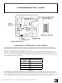
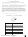
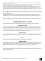
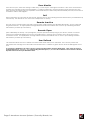
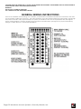
User/Installation
Manual
AAS 11-65000
“Your Partner in Access Control”
www.americanaccess.com
Contents
INTRODUCTION4
CARD ID NUMBERS AND FACILITY CODES
4
SETTING THE FACILITY (SYSTEM) CODE
4
ORDERING ADDITIONAL CARDS FOR YOUR SYSTEM
5
USING SK-NET™ SOFTWARE
5
PROGRAMMING THE 11-65000
6
PROGRAMMING 11-65000 USING A TERMINAL PROGRAM
6
PROGRAMMING WITH PROGRAM CARDS
7
CONFIGURING THE 11-65000
8
LIMITED USE CARDS
8
DEFINING INPUTS
8
ACCESS CARD PROGRAMMING/STATUS
10
PROGRAMMING ACCESS CARDS INTO TIME ZONES
10
PROGRAMMING CARDS FOR LIMITED USE
11
DOOR CONTROL
13
SYSTEM SETTINGS
14
DATE AND TIME
14
INSTALLATION21
GENERAL WIRING INSTRUCTIONS
22
COMMUNICATIONS WIRING FOR SINGLE-READER SYSTEMS
23
REMOTE READER CONNECTION
26
FACTORY SETTINGS
27
APPENDIX A
28
Page 2 American Access Systems / Security Brands, Inc.
Two-Year Limited Warranty
AAS 2-Year Limited Warranty
This warranty applies to:
All product or equipment specifically and solely designed for and manufactured by American Access Systems, Inc.
Any equipment used in AAS products that is not manufactured by American Access Systems, Inc. (this includes all
products purchased by AAS for OEM purposes) is liable and subject to warranty terms of that specific manufacturer.
Those products used by AAS which are not covered by the AAS 2-Year Limited Warranty are: TekTone, HID, SecuraKey
and Omniprint.
If your AAS product is defective and returned within two years of the date of purchase, we will repair it, or at our
option, replace it at no charge to you. If we repair your AAS product, we may use new or reconditioned parts. If
we choose to replace your AAS product, we may replace it with a new or reconditioned unit of the same or similar
design. The repair or replacement will be warranted for 90 days or the remainder of the original two-year warranty
period, whichever is longer.
Limitations:
Implied warranties, including those of fitness for a particular purpose and merchant ability (an unwritten warranty that
the product is fit for ordinary use), are limited to two years from date of purchase. We will not pay or recompense for
loss of time, inconvenience, loss of use of your AAS product, service calls or property damage caused by your AAS
product, its failure to work or any other incidental or consequential damages. Some states do not allow limitations
on how long an implied warranty lasts or the exclusion or limitation of incidental or consequential damages, so the
above exclusions or limitations my not apply to you.
What we ask you to do:
To get warranty service for your AAS product, you must provide proof of the date of purchase. Contact the original
dealer or installer of the product and return your AAS product along with the receipt to them. If you have problems
locating the dealer or installer, please contact American Access Systems, Inc at (303) 799-9757 and we will direct you
to an authorized dealer or distributor of AAS products. If you ship your AAS product, you must prepay all shipping
costs. We suggest that you retain your original packing material in the event you need to ship your AAS product.
On return, include your name, address, phone number, proof of date of purchase, RMA # (obtained through an
authorized AAS dealer or distributor) and a brief description of the operating problem. IF AN RMA # IS NOT LISTED ON
THE EXTERIOR OF THE PACKAGING OR THE PAPERWORK YOU INCLUDE, THE PRODUCT WILL BE RETURNED TO YOU. NO
SERVICE WORK WILL BE PERFORMED UNTIL AN RMA # IS OBTAINED AND INCLUDED WITH YOUR SHIPMENT TO US.
What this warranty does not cover:
This warranty does not cover defects resulting from accidents, damage while in transit, alterations, unauthorized
repair, and failure to follow instructions, misuse, fire, flood or acts of God. Nor do we warrant your AAS product to be
compatible with any particular external device or peripheral. If the warranty has expired on your AAS product or if
your product is NOT covered, please contact your dealer or installer for advice on whether we will repair your AAS
product and other repair information, including estimated repair costs and other charges.
This warranty is the only one we give on our products, and it sets forth all of our responsibilities regarding your AAS
product. There are no other express warranties.
State Law Rights:
This warranty gives you specific legal rights and you may also have other rights that vary from state to state.
Page 3 American Access Systems / Security Brands, Inc.
Introduction
The 11-65000 is a stand alone card access control system that will control access to a passageway for 65,000
individuals in 15 weekly time schedules (Time Zones). Certain Access Cards may be designated as “Limited Use”
cards, and their use may be restricted to allow access for a given number of days or weeks or for a given number of
times.
Programming of cards and most other programming functions are easily accomplished from outside the unit, using a
PD-26 Programming Deck. (A set of 15 programming cards). The 11-65000 may also be programmed with a terminal
or PC. Transaction information is stored by the unit and may be downloaded to a terminal, PC, or serial printer. 5000
transactions may be stored at one time
The 11-65000 has three inputs. Each input may be programmed by the user to function as a Door Monitor, Tamper
Monitor, Remote Open, Remote Inactive, Bell, Arming Circuit, or User Defined Input. Factory Defaults for these inputs
are 1 - Door Monitor, 2 - Remote Open (REX), and 3 - Remote Inactive.
A second “remote” reader (SK-029W) may be added to the 11-65000 to control access through a single passageway
in both directions.
The 11-65000 utilizes state of the art electronics in providing a product that is highly sophisticated, yet inexpensive.
Patented slotless TOUCH CARD® reader technology protects the unit from weather and vandalism. Simply place
the card on the stainless steel TOUCH CARD® reader plate, and the card is read instantly and accurately -- in any
weather. A green light indicates that access has been granted. Since the 11-65000 has non-volatile memory,
reprogramming after a power loss is unnecessary.
Card ID Numbers and Facility Codes
Access cards used with the 28SA-Plus have two encoded numbers: the ID number which is different on each
card, and the Facility Code, (also called a system or site code) which is the same for all cards at a given site. ( The
programming cards should also have the same Facility Code.) When a card is read, the system first verifies the Facility
Code, then it checks the ID Number against its internal “card list” in memory to see if the card is void or valid. It also
checks the Time Zone, the card’s Antipassback status, and the Limited Use count.
Setting the Facility (System) Code
IMPORTANT
Before programming or using a new unit,
the correct Facility Code must be set.
When power is first applied, or when the reset button is pushed (see Figure 1) the LED will flash red and green
alternately. While the LED is flashing, place either a Programming Card or an Access Card with the proper facility
code onto the TOUCH CARD® reader plate and remove it (note LED turns solid green). The 11-65000 will “remember”
the facility code and retain it until reprogrammed. After setting the facility code, wait for the LED to stop flashing
before attempting to use the program deck to program cards into the unit.
When placing standard cards on the reader, make sure that the arrow points up and the logo faces you. The
exception is Photo ID cards, where the arrow points up, and the photo faces you.
To change a facility code (or to set the facility code if the LED is not flashing red/green) remove the unit from the
wall to gain access to the reset button (see Figure 1). With power still connected, momentarily depress the reset
button. The LED indicator will flash red and green alternately. If the reset button is pushed, but no card is placed on
the TOUCH CARD® reader plate before the LED indicator times out, the system code will be unchanged. In some
cases it may be necessary for the unit to recognize more than one facility code. Typical instances are when a service
technician needs to program a unit and the original program deck cannot be located, or when other devices such
as bar-code scanners, transmitter-type gate openers or proximity readers are connected to the remote reader input
(particularly if they are 26-bit devices).
The 11-65000 can be set to recognize up to three different facility codes. To program multiple facility codes, follow
the procedure above for programming a single facility code, but place a card with the second facility code (and
third facility code if necessary) on the TOUCH CARD® reader plate (or at the remote input device) before the red/
green LED indicator times out.
Note that it is not generally recommended to combine sets of Secura Key cards with different facility codes, because
the unit cannot distinguish between access cards having different facility codes and the same ID number.
Page 4 American Access Systems / Security Brands, Inc.
Ordering Additional Cards For Your System
When you wish to add to an existing set of cards, always order additional cards with the same facility code as your
existing cards, and with sequential (Card ID) numbering starting one number higher than the highest-numbered card
currently in use. It is worth waiting a short time for these cards to be correctly encoded by the factory, as this will
guarantee proper operation and the highest security for your system.
Using SK-NET™ Software
SK-NET™ is a powerful Windows® (95/98/NT4.0) compatible software application program designed to monitor and
control a network of up to 200 11-65000 Units per location. SK-NET is the software of choice when communicating or
programming 11-65000 Units either as stand alones or complete systems. If you do not use SK-NET™ software, you may
use a terminal or terminal software to program the individual units (see below, “Using a Terminal Program”). You may
also use a program deck for limited programming functions of the individual units.
If you are already familiar with other access control programs, you will find that SK-NET™ is different than what you
are used to. The user interface follows Microsoft Windows® conventions, rather than a traditional menu structure.
SK-NET™ Explorer works similarly to the Windows® Explorer. As in other Windows® applications, right-click menus are
used extensively.
The basic version of SK-NET™ allows a single reader network connected to the PC; the Multiple Location Dial-up
version (SK-NET™-MLD) allows modem communications and unlimited remote locations. See the SK-NET user manual
for detailed instructions.
Page 5 American Access Systems / Security Brands, Inc.
PROGRAMMING THE 11-65000
Programming 11-65000 Using a Terminal Program
Programming the 11-65000 with a personal computer or terminal is easy because all programming functions are
accomplished using simple to understand menus. Just choose what you want to do from the menu, and you will
then either be given a sub-menu to further describe the required function, or you will be asked to enter information
necessary to carry out the programming function you desire.
Secura Key’s SA-NET™ Software was developed to program one or more 28SA-Plus’s, to upload transactions to a
PC,and to produce event reports. SA-LINKTM software is also available for basic programming and transaction viewin
If you use a personal computer, and it does not have a built-in terminal or communications program, use one of the
many available commercial programs, such as Procomm or a Windows terminal program. Your computer or terminal
(or serial printer) should be set as follows:
Baud
9600 (or higher)
Start bit
1
Data bits
8
Stop bit
1
Parity
None
Emulation
ANSI (or compatible)
BAUD RATE
The Baud Rate of the ENTRACOMP® 28SA-Plus defaults to 9600, but may be changed via the menu system using a
PC or terminal. Baud Rates up to 38,400 are possible, although not all PC COM ports are capable of high data rates.
Once changed, the new Baud Rate will become effective the next time you log onto the system or connect a
printer. The Baud Rate may also be set using a Programming Deck (see page 29). Note that if you are using Secura
Key software or any other terminal software, the Baud Rate at the reader must match the Baud Rate at the PC.
Page 6 American Access Systems / Security Brands, Inc.
Logging On and Off.
To prevent unauthorized programming of the 11-65000 when using a PC or terminal, it is necessary to enter a
password at the beginning of every programming session. When communications are first established with the
ENTRACOMP® 28SA-Plus, the screen will say:
WELCOME TO ENTRACOMP® 28SA-Plus
ENTER PASSWORD:
The default password is “12345”. When you begin your first programming session, enter “12345” and press the “ENTER”
key when the password is requested. The main menu will then be displayed.
During this first programming session, use the “Password” menu selection of the System Settings Menu to set a
password of your choice. You may change your password at any time using the “Password” selection of the menu. It
is not necessary to set or use a password when programming your unit with the Program Deck.
Note that when using Secura Key’s SK-NET TM software, it is recommended that when you change the password
you do so from the location properties while connected to the 28SA-Plus. A separate manual is included with the
SK-NETTM software.
If you should forget your password, you must turn off the power to the unit. Then, while holding in the reset button
(see Figure 1), turn the power back on. This will reset the password to “12345.” This same procedure also re-calibrates
the sensors in the reader, so be sure there is no magnetism near the reader (i.e., a card) when the password is being
reset. Wait for the red/green flashing LED to time out (stop blinking) before putting cards on the TOUCH CARD®
reader plate. This procedure should be done with the unit at average operating temperatures; not in extreme heat
or cold.
When the reader is connected to a PC or data terminal, the reader will automatically logoff after four minutes with
no keyboard activity. You will then be required to enter the password again to access the system. Automatic logoff
occurs while in any menu or sub-menu except when displaying current transactions. It is advisable to exit the system
when you are finished by using the “Logoff” selection of the main menu.
Programming with Program Cards
There are two kinds of cards used with the 1-65000: Access Cards and Program Cards. Access Cards are used by
individuals to gain access to the passageway. Program Cards are used to tell the ENTRACOMP® 28SA-Plus what to
do.
The Program Cards are as follows:
“0”
ZERO
“1”
ONE
“2”
TWO
“3”
THREE
“4”
FOUR
“5”
FIVE
“6”
SIX
“7”
SEVEN
“8”
EIGHT
“9”
NINE
“*”
THRU
“VALID”
VALIDATE
“VOID”
VOID OR CANCEL
“SET TIMER”
“ACTIVE/INACTIVE”
SET LATCH, ANTIPASSBACK TIMER, TIME/DATE
ACTIVATE OR INACTIVATE SYSTEM
Page 7 American Access Systems / Security Brands, Inc.
Most basic functions of the 11-65000 may be programmed by placing the Program Cards on the TOUCH CARD®
reader plate in a proper sequence.
However, some things (such as configuring the inputs, configuring Time Zones, Holidays, Limited Use, antipassback or
setting the password) may only be programmed using a personal computer or terminal.
As with Access Cards, Program Cards are magnetically encoded with a common facility code and instruction
information. The facility code of your Program Cards is normally the same as the facility code of your Access Cards.
Your unique facility code is what prevents Program Cards from other systems from programming your system. There
are 15 different Program Cards. There are ten number cards (0 through 9) and five function cards. These 15 Program
Cards are attached to each other in a convenient Program Deck configuration (PD-26).
It is helpful to think of placing a Program Card on the TOUCH CARD® reader plate as depressing a key on a keyboard
or key pad. You may begin programming at any time by placing the first Program Card of the sequence on the
TOUCH CARD® reader plate. At this point the LED indicator will show an amber color. When you remove the Program
Card from the TOUCH CARD® reader plate, the LED indicator will flash the amber color awaiting the next Program
Card. Placement of the next Program Card on the TOUCH CARD® reader plate causes the amber LED to stop
flashing and become solid.
In like manner, the remainder of the Program Cards for the programming sequence are placed on the TOUCH
CARD® reader plate. At the end of the programming sequence, the LED indicator will flash green to indicate that
the programming instruction has been accepted.
While programming, it is necessary to place the next card of the sequence on the TOUCH CARD® reader plate while
the LED indicator is flashing amber (you have approximately 10 seconds between each card). If the amber LED
times out (stops blinking) it will be necessary to restart the programming sequence. Should an error be made in the
programming sequence, the LED indicator will flash red instead of green.
Configuring the 11-65000
The 11-65000 defaults to the maximum configurations of cards, transactions, and Time Zones. Only the Limited Use
card range and Input Point definitions require configuration, which can only be done using a PC or terminal.
Limited Use Cards
The maximum number of cards that may be used as limited use cards is 4000. The default setting always starts at
card number one and ends at 4000. However, it is possible to choose the exact block of cards that you wish to
have operate as limited use cards. To change the block of cards that may be set for limited use, choose 5 (System
Configuration) on the Main Menu. Then select item 4 (Limited Use Cards) on the Configuration Menu. Enter the first
number of the desired block of cards. The starting sequential number for limited use cards can be set to any value
(1 - 65000). The ending number will automatically be the Starting Number + 4000 (65000 maximum), but it may be
changed. For more information on how limited use cards function, see page 15.)
Defining Inputs
The 11-65000 has three inputs. In the default configuration, the inputs are set as follows: 1) Door Monitor, 2) Remote
Open, and 3) Remote Inactive. Using the menu system these inputs may each be programmed to function in one of
seven ways (described below). If the input feature is not needed, use the System Configuration menu to set each
input to Disabled.
Tamper
When the input is activated, a “Tamper” message is recorded, and the unit becomes inactive until the input is
deactivated. If the unit is connected to a printer, the message is also sent immediately.
Arming Circuit
This configuration is normally used in parking lot situations. The input would normally be connected to an output of a
vehicle detector. The unit will not allow access without the detector sensing the presence of a vehicle. If an entry
attempt is made while the input is not activated, entry will be denied and an “Arming Input” error message will be
recorded. If the unit is connected to a printer, the message is also sent immediately. (Jumper if unused).
Door monitor
If the door is open, other than during a valid entry, a “Door Open” message is recorded. If the unit is connected to
a printer, the message is also sent immediately. If, during a valid entry, the Door Monitor senses that the door has
been opened and closed prior to expiration of the latch timer, the latch relay will immediately be reset; this feature is
sometimes called “anti-tailgate.”
Page 8 American Access Systems / Security Brands, Inc.
Door Monitor
If the door is open, other than during a valid entry, a “Door Open” message is recorded. If the unit is connected to
a printer, the message is also sent immediately. If, during a valid entry, the Door Monitor senses that the door has
been opened and closed prior to expiration of the latch timer, the latch relay will immediately be reset; this feature is
sometimes called “anti-tailgate.”
Bell
When activated, the unit sends an ASCII “bell” signal to the PC (if monitoring real-time transactions) or Serial Printer (if
connected). This will cause a PC and some serial printers to “beep.”
Remote Inactive
The unit may be made inactive remotely using a switch. While inactive the LED blinks Red slowly, and no cards will
be granted access. An appropriate message will be recorded and will be sent to the PC (if monitoring real-time
transactions) or Printer (if connected).
Remote Open
(Also called Request to Exit). The passageway may be opened remotely using a push button, switch or contact
output from an Exit PIR designed for access-controlled doors. Remote Open functions even when the unit is in
an inactive mode. An appropriate message will be recorded and will be sent to the PC (if monitoring real-time
transactions) or Printer (if connected).
User Defined
This selection allows the user to define the action taken when the input is activated. The user may create the
transaction text message to be recorded and decide if the 11-65000 is to grant access and if the Bell signal is to be
sent.
To change the definition of an input, choose 5 (System Configuration) from the Main Menu. Then, from the System
Configuration Menu, choose 1, 2, or 3 depending whether input 1, 2, or 3 is to be redefined. Then select the desired
input function from the Input Definition Menu.
Page 9 American Access Systems / Security Brands, Inc.
ACCESS CARD PROGRAMMING/STATUS
PROGRAMMING ACCESS CARDS INTO TIME ZONES
Access Cards are programmed into one of 15 Time Zones. The particular Time Zone into which an Access Card is
programmed determines if and when a cardholder will be granted access. Programming an Access Card into Time
Zone “0” makes the card void (it never is allowed access). Programming an Access Card into Time Zone “1” makes
a card valid for entry without restriction as long as the 11-65000 is in an active mode. Programming an Access Card
into any other Time Zone restricts the card’s usage, depending upon how the Time Zone is set (see page 31 for setting
Time Zones).
Using the Menu System
To program cards using the menu system, select item 2 (Cards) from the main menu. Then select 1 (Program Cards
Into a Time Zone) from the Card menu. Then in the Program Cards dialog box, enter the Time Zone into which the
cards are to be programmed, the starting number of the block of cards to be programmed, and the ending number
of the block of cards to be programmed. To program one card only, use its number as the starting and ending
number.
Using a Progrsmming Deck
Programming a single card is slightly different than programming a block of cards when using the Programming Deck.
Programming a Single Card
To program a single card into a Time Zone, place the sequence of Program Cards representing the card number on
the TOUCH CARD® reader plate. Then place the “*” (THRU) card on the TOUCH CARD® reader plate, remove it. Then
place the sequence of cards representing the Time Zone on the TOUCH CARD® reader plate, remove it and place
the “*” (THRU) card on the TOUCH CARD® reader plate. Then place the “VALID” card on the TOUCH CARD® reader
plate and remove it.
Example: Program card number 11 into Time Zone 12. Place the “1” card on the TOUCH CARD® reader plate,
remove it and again place the “1” card on the TOUCH CARD® reader plate, remove it and place the “*” (THRU)
card on the TOUCH CARD® reader plate. Remove it and place the “1” card on the TOUCH CARD® reader plate,
remove it and place the “2” card on the TOUCH CARD® reader plate, remove it and place the “*” (THRU) card on
the TOUCH CARD® reader plate. Then place the “VALID” card on the TOUCH CARD® reader plate, and remove it.
1 + 1 + * + 1 + 2 + * + VALID
Programming a Block of Cards
To program a block (continuous sequence) of cards into a particular Time Zone, place the sequence of cards
representing the first card number of the block on the TOUCH CARD® reader plate, then the “*” (THRU) card, then
the sequence of cards representing the last card number of the block, then the “*” (THRU) card. Then place the
sequence of cards representing the Time Zone on the TOUCH CARD® reader plate, remove it and place the “*”
(THRU) card on the TOUCH CARD® reader plate. Then place the “VALID” card on the TOUCH CARD® reader plate.
Example: Program cards 5 thru 22 into Time Zone 6.
Place the “5” card on the TOUCH CARD® reader plate, remove it and place the “*” (THRU) card on the TOUCH
CARD® reader plate, remove it and place the “2” card on the TOUCH CARD® reader plate, remove it and again
place the “2” card on the TOUCH CARD® reader plate, remove it and place the “*” (THRU) card on the TOUCH
CARD® reader plate, remove it and place the “6” card on the TOUCH CARD® reader plate, remove it and place
the “*” (THRU) card on the TOUCH CARD® reader plate, remove it and place the “VALID” card on the TOUCH CARD®
reader plate, and remove it.
5 + * + 2 + 2 + * + 6 + * + VALID
VOIDING CARDS . To void (cancel) Cards, program them into Time Zone “0,” or, using the Program Deck, enter the
card number or number range and then use the VOID card.
Page 10 American Access Systems / Security Brands, Inc.
PROGRAMMING CARDS FOR LIMITED USE
Only those Access Cards that have been designated as Limited Use Cards may be programmed for limited use (see
page 10). Access Cards in Time Zones “0” or “1” may not be programmed for limited use. Changing the Time Zone of
an Access Card will have no effect on its limited use status except that an Access Card programmed into Time Zones
“0” or “1” will be deleted from limited use.
Limited use restrictions may be set for either limited number of uses, limited number of days from “now”, limited
number of weeks from “now”, limited number of days from first use, use counter, or no limited use restrictions. Any
Access Card within the block of cards configured for limited use may be set to have one of these limited use
functions, each with its own number of days, or uses as described below.
Limited Number of Uses
Number of uses may be set to from 1 to 500. Each time access is granted, the number of uses is reduced by one until
there are no uses left. At this point, further access will be denied until more uses are programmed. Access Cards are
still subject to Time Zone restrictions.
Limited Number of Days
The number of days that the Access Card will be granted access (up to 500) may be set when this limited uses option
is selected. Each day the number of days counter will be reduced by one until no days are left. At this point the
Access Card will be denied further access until more days are programmed. Time Zone restrictions must also be met
for access to be granted.
Limited Number of Weeks
The number of weeks that the Access Card will be granted access (up to 500) may be set when this limited uses
option is selected. Each week the number of weeks counter will be reduced by one until no weeks are left. At this
point the Access Card will be denied further access until more weeks are programmed. Time Zone restrictions must
also be met for access to be granted.
Limited Number of Days From First Use
This Limited Use option is similar to the limited number of day’s selection, except that the number of days of access
(up to 500) is counted from the day the Access Card is first granted access.
Count Number of Uses
This selection does not actually restrict access but counts how many time access has been granted. Therefore,
no number of days or uses are entered. Selecting this choice for a card merely resets the counter to 0. Each time
access is granted, the counter is incremented by one. The number of access granted may be viewed using the Status
Menu. The counter can only count to 500. If more than 500 accesses have been granted since the counter was last
reset, the status report will indicate “>500”.
No Limited Use
This option is used to remove any of the above limited use settings. To program Access Cards for Limited Use, choose
2 (Cards) from the Main Menu. Then select 2 (Program Limited Use Cards) followed by the Limited Use selection from
the Limited Use Menu and enter the required number and the first and last card numbers for the range of cards to be
programmed.
Page 11 American Access Systems / Security Brands, Inc.
Card Status
Reports on the status of Access Cards may be obtained by choosing 2 (Cards) from the Main Menu and then
selecting 3 (Display Card Status) from the Cards Menu. Card status is always displayed in numerical order of the block
specified. If a particular Time Zone is selected, only those cards of the selected block that are in the Time Zone will be
displayed. If “ALL” is chosen for the Card Time Zone entry, all cards of the selected block will be displayed.
If a particular Time Zone is chosen, the number of the card, the limited use status (i.e., None, Days, Weeks, Uses, or
Times), and the remaining uses, days, weeks, or the times access has been granted will be displayed. If “ALL” is
selected, the same information as above plus the Time Zone of each card will be displayed.
Antipassback Forgive
This selection allows you to specify all cards or a range of cards to be immediately set to a Neutral status for Real
Antipassback. This allows access to any card previously denied access due to a Real Antipassback violation (e.g.
attempting a second badging at an IN reader). This only affects cards programmed into Time Zones with Real
Antipassback enabled. The range may be set to apply to one card or all cards. Once forgiven, a card’s Real
Antipassback status (IN or OUT) will be determined by the next Real Antipassback reader in which the card is used.
For more information on Antipassback, see page 24.
Frogive Antipassback using the Menu System
Choose 2 (Cards) from the Main Menu, then choose 4 (Antipassback Forgive) from the Cards Menu. You may then
specify All or Range. If you select Range, you must enter beginning and ending card numbers for the range and
enter Y (Yes) to the confirmation prompt.
FORGIVE ANTIPASSBACK USING THE PROGRAMMING DECK To forgive antipassback for all cards using the
programming deck, place the * card on the TOUCH CARD® reader plate followed by the SET TIMER card. You cannot
forgive a range of cards using the program deck.
Antipassback Disable/Enable
Occasionally, due to a gate or door at an IN or OUT reader being temporarily inoperative, cardholders’ antipassback
status may become out of sync, necessitating the disabling of antipassback at the reader. Although this can
be done with the SA-NET TM software by disabling APB in all applicable Time Zones, it may be simpler to make a
temporary change using the program deck.
To disable antipassback at a reader using the program deck, place the VOID card on the TOUCH CARD® reader
plate followed by the SET TIMER card. This will allow access to any otherwise valid card regardless of that card’s
current IN/OUT Antipassback status.
To re-enable antipassback at a reader using the program deck, place the VALID card on the TOUCH CARD® reader
plate followed by the SET TIMER card.
Page 12 American Access Systems / Security Brands, Inc.
Door Control
The 11-65000 provides complete control of the passageway via the menu system. Some door control functions may
also be performed using the Programming Deck.
Remote Open Via the Menu
To open the door using the menu system, choose 3 (Door Control) from the Main Menu and then 1 (Open Door Now)
from the Door Menu. You will be asked if you are sure. If you answer yes, the door will be opened for the same latch
time period as when a card is used to open the door. An appropriate message will be recorded and sent to the PC
(if monitoring real-time transactions) or Printer (if connected). See page 11 for Remote Open Using Inputs.
Door Unlock Mode
The relay may be set to stay latched (door unlocked) during periods when access control is unwanted. While in the
“DOOR UNLOCK” mode, the relay stays activated, and the LED indicator will flash green approximately once every
second. The unit may not be programmed with the programming deck, nor will it recognize Access Cards while in
the “DOOR UNLOCK” mode.
DOOR UNLOCK VIA THE MENU . To activate the Door Unlock mode, choose 3 (Door Control) from the Main Menu.
Then choose 2 (Unlock Door Indefinitely) from the Door Menu. An appropriate message will be recorded and will be
sent to the PC (if monitoring real-time transactions) or Printer (if connected). To deactivate the Door Unlock Mode,
choose 5 (Return To Normal Mode) from the Door Menu or place the “ACTIVE/INACTIVE” card of the Programming
Deck on the TOUCH CARD® reader plate and remove it DOOR UNLOCK USING THE PROGRAMMING DECK. To set
the unit to the DOOR UNLOCK Mode, place the “*” (THRU) card on the TOUCH CARD® reader plate, remove it
and place the “ACTIVE/INACTIVE” card on the TOUCH CARD® reader plate and remove it.
* +ACTIVE/INACTIVE
To return the 11-65000 to normal operation, place the “ACTIVE/INACTIVE” card on the TOUCH CARD® reader plate
and remove it or choose 5 (Return To Normal Mode) from the Door Menu.
Door Unlock Until a Set Time
Using the Menu System, the 11-65000 may be put into the door unlock mode until a user selected date and time.
Choose 3 (Door Control) from the Main Menu. Then choose 3 (Door Unlock Until A Set Time). From the dialog box
enter the date and time that the Door Unlock mode is to expire. An appropriate message will be recorded and sent
to the PC (if monitoring real-time transactions) or Printer (if connected).
You may cancel the door unlock mode at any time choosing 5 (Return To Normal Mode) from the Door Menu or
placing the “ACTIVE/INACTIVE” card of the Programming Deck on the TOUCH CARD® reader plate and removing it.
Incative Mode
The 11-65000 may be made inactive for entry with a card by placing the “ACTIVE/INACTIVE” card of the
Programming Deck on the TOUCH CARD® reader plate and then removing it. You may also choose 3 (Door Control)
from the Main Menu and then 4 (Make Reader Inactive Indefinitely) from the Door Menu. An appropriate message
will be recorded and sent to the PC (if monitoring real-time transactions) or Printer (if connected).
OOR UNLOCK USING THE PROGRAMMING DECK. To set the unit to the DOOR UNLOCK Mode, place the “*” (THRU)
card on the TOUCH CARD® reader plate, remove it and place the “ACTIVE/INACTIVE” card on the TOUCH CARD®
reader plate and remove it.
* +ACTIVE/INACTIVE
To return the 11-65000 to normal operation, place the “ACTIVE/INACTIVE” card on the TOUCH CARD® reader plate
and remove it or choose 5 (Return To Normal Mode) from the Door Menu.
Door Unlock Until a Set Time
Using the Menu System, the 11-65000 may be put into the door unlock mode until a user selected date and time.
Choose 3 (Door Control) from the Main Menu. Then choose 3 (Door Unlock Until A Set Time). From the dialog box
enter the date and time that the Door Unlock mode is to expire. An appropriate message will be recorded and sent
to the PC (if monitoring real-time transactions) or Printer (if connected).
You may cancel the door unlock mode at any time choosing 5 (Return To Normal Mode) from the Door Menu or
placing the “ACTIVE/INACTIVE” card of the Programming Deck on the TOUCH CARD® reader plate and removing it.
Incative Mode
The 11-65000 may be made inactive for entry with a card by placing the “ACTIVE/INACTIVE” card of the
Programming Deck on the TOUCH CARD® reader plate and then removing it. You may also choose 3 (Door Control)
from the Main Menu and then 4 (Make Reader Inactive Indefinitely) from the Door Menu. An appropriate message
will be recorded and sent to the PC (if monitoring real-time transactions) or Printer (if connected).
Page 13 American Access Systems / Security Brands, Inc.
SYSTEM SETTINGS
Date and Time
The 11-65000 stores 5000 transactions. In order to know when a transaction has occurred, it is necessary to set the
internal clock to the correct date and time. Time is kept in a 24 hour (military) manner. Even if you do not intend to
use transaction information, it is necessary to set the date and time for proper operation of Time Zones. Once set, the
Automatic Daylight Savings Time Adjustment feature will automatically change the time to activate and de-activate
Daylight Savings Time (See page 35).
Note that the 28SA-Plus and the various Secura Key software programs are all “Year 2000 Compliant.”
Setting Date and Time Using the Menu
To set the date and time choose 4 (System Settings) from the Main Menu. Then select 1 (Date) from the System
Settings Menu to set the date followed by 2 (Time) from the System Settings Menu to set the time.
Setting the Date and Time Using the Cards
To set the date, place the cards on the TOUCH CARD® reader plate that represent the month (1 - 12), then place
the “*” on the TOUCH CARD® reader plate, then place the cards on the TOUCH CARD® reader plate that represent
the day of the month (1 - 31), then place the “*” on the TOUCH CARD® reader plate, then place the cards on the
TOUCH CARD® reader plate that represent the last two digits of the year (e.g., 99), then place the “SET TIMER” card
on the TOUCH CARD® reader plate and remove it.
Example: Set date to 9/28/99.
Place the “9” card on the TOUCH CARD® reader plate and remove it. Then place the “*” card on the TOUCH
CARD® reader plate and remove it, and place the “2” card on the TOUCH CARD® reader plate and remove it, and
place the “8” card on the TOUCH CARD® reader plate and remove it, and place the “*” card on the TOUCH CARD®
reader plate and remove it. Then place the “9” card on the TOUCH CARD® reader plate and remove it and place
the “9” card on the TOUCH CARD® reader plate and remove it. Then place the “SET TIMER “ card on the TOUCH
CARD® reader plate and remove it.
9 + * + 2 + 8 + * + 9 + 9 + SET TIMER
To set the time, place the cards on the TOUCH CARD® reader plate that represent the hour (0 - 24), then place the
“*” on the TOUCH CARD® reader plate and remove it, then place the cards on the TOUCH CARD® reader plate that
represent the minutes (0 - 60), and then place the “SET TIMER” card on the TOUCH CARD® reader plate and remove
it.
Example: Set time to 13:27 hours (1:27 pm).
Place the “1” card on the TOUCH CARD® reader plate and remove it, then place the “3” card on the TOUCH
CARD® reader plate and remove it. Then place the “*” card on the TOUCH CARD® reader plate and remove it,
then place the “2” card on the TOUCH CARD® reader plate and remove it, then place the “7” card on the TOUCH
CARD® reader plate and remove it. Then place the “SET TIMER” card on the TOUCH CARD® reader plate and
remove it.
1 + 3 + * + 2 + 7 + SET TIMER
Latch Timer
The output from the relay may be set to any number of seconds from 1 to 30. Setting the latch timer to “0” produces
a 0.25 second output, timed from when a valid card is placed on the TOUCH CARD® reader plate.
Setting the Latch Timer Via the Menu
To set the Latch Timer using the Menu System, choose 4 (System Settings) from the Main Menu. Then from the System
Settings Menu, select 3 (Latch Timer).
Setting the Latch Timer Using Cards
To set the Latch Timer using the Program Deck, place on the TOUCH CARD® reader plate the sequence of Program
Cards representing the number of seconds the latch is to be on, then place the “SET TIMER” card on the TOUCH
CARD® reader plate and remove it.
Example: Set latch timer for 15 seconds.
Place the “1” card on the TOUCH CARD® reader plate, remove it and place the “5” card on the TOUCH CARD®
reader plate, remove it and place the “SET TIMER” card on the TOUCH CARD® reader plate, and remove it.
1 + 5 + SET TIMER
Page 14 American Access Systems / Security Brands, Inc.
ANTIPASSBACK
Antipassback is a feature designed to prevent or discourage an authorized cardholder from passing their card back
to an unauthorized person who wishes to re-use the same card to obtain access. The most common application for
Antipassback is Parking. Antipassback is not generally practical for use by office or factory personnel, unless turnstiles
are in use. When Antipassback is enabled, the 28SA-Plus will temporarily void a card after the first use, so that any
person attempting to reuse the same card in the same reader will be denied access. This temporary void status is
stored in memory in the 28SA-Plus. Different types of Antipassback use different methods to void and reset the card.
The 28SA-Plus offers two types of Antipassback: Real and Timed.
REAL ANTIPASSBACK requires the use of a 28SA-Plus and a Remote Reader. The main reader (the 28SA-Plus) can be
designated as an In reader or an Out reader; the Remote reader automatically takes the opposite type. In memory,
each cardholder has In, Out, or Neutral Antipassback status, which is determined by the antipassback type of the
reader where the card was last used The cardholder must have Out status to use an In reader and vice-versa. As
long as the IN and OUT readers are used in alternating sequence, there will be no restriction; if a card is used at an IN
reader twice in a row, or at an OUT reader twice in a row, the second access attempt is denied.
Real Antipassback only applies at one set of Primary / Remote readers. Even if multiple readers are connected to a
PC using Smart Switches and SA-NETTM software, other 28SA Units at the same site will be unaware of the cardholder’s
IN/OUT status change.
TIMED ANTIPASSBACK
sets the card to Void status for a user-defined time period. Once the time period expires, the card can be re-used in
the reader. For every card use, a comparison is made in transaction history to that card’s previous use to see if the
time period has elapsed. Timed antipassback only applies at a single reader; other 28SA-Plus units at the same site will
not be able to make a time comparison. Note that if a Remote Reader is connected to the 28SA-Plus, once a given
card is used, it cannot be reused at either the remote or main reader until the time period has expired.
CONFIGURING REAL ANTIPASSBACK
To configure a 28SA-Plus and Remote Reader for Real Antipassback, you must first set the 28SA-Plus (Primary Reader)
as either an IN or OUT reader. To set reader IN/OUT status, choose 5 (Configuration Menu), select 5 (Primary Reader),
then select N (None), I (In), O (Out), or press ESC to exit. The Remote Reader automatically takes the opposite status.
Real Antipassback cannot be set up with the program deck.
To be affected by Real Antipassback, cards must be assigned to a Time Zone with Real Anti-Passback enabled. See
Page 13 for information on how to assign a card to a Time Zone, and see Page 32 for information on how to set Real
Anti-Passback in a Time Zone.
The DAILY APB FORGIVE HOUR feature is also available on the Configuration Menu. During the course of the day,
cardholders’ Antipassback (APB) status may get out of synchronization when entering or exiting without using a card
(due to disabled parking gates, exiting after-hours, etc.) DAILY APB FORGIVE will set all cards to a Neutral status, so
that all cards will work the first time they are used on the following day, regardless of their Antipassback status at the
end of the previous day. After the first usage, the card’s Real Antipassback status will change normally.
CONFIGURING TIMED ANTIPASSBACK
If Timed Antipassback is selected, a card used for entry is made temporarily void for a user-definable amount of
waiting time. The antipassback waiting time may be set to any number of minutes from 1 to 30. However, the actual
waiting time will fluctuate between the time set and the time set plus one minute. Thus, if the antipassback time is
set to 5 minutes, users will have to wait a minimum of 5 minutes and a maximum of 6 minutes before reentry will be
allowed. Setting the antipassback waiting time to 0 will disable the Timed Antipassback feature and reentry will be
allowed immediately.
SETTING ANTIPASSBACK WAITING TIME USING A MENU
To set the Antipassback Waiting Time using the Menu System, choose 4 (System Settings) from the Main Menu. Then
from the System Settings Menu, select 4 (Antipassback Timer).
SETTING ANTIPASSBACK WAITING TIME USING CARDS
To set the Antipassback Waiting Time using the Program Deck, place on the TOUCH CARD® reader plate the
sequence of cards representing the number of minutes of the minimum waiting period (1 to 30), then place the “*”
card on the TOUCH CARD® reader place and remove it, then place the “SET TIMER” card on the TOUCH CARD®
reader plate and remove it.
Example: Set antipassback waiting time to 3 minutes.
Place the “3” card on the TOUCH CARD® reader plate, remove it, and place the “*” on the TOUCH CARD® reader
plate, remove it, and place the “SET TIMER” card on the TOUCH CARD® reader plate, and remove it.
3 + * +
SET TIMER
See Pages 17-18 for more information on Antipassback Control.
Page 15 American Access Systems / Security Brands, Inc.
PASSWORD PROTECTION
To prevent unauthorized programming of the 11-65000 when using a personal computer or terminal, it is necessary to
enter a password at the beginning of every programming session. The default password is “12345”. When you begin
your first programming session, enter “12345” and press the “ENTER” key when the password is requested.
The 11-65000 will automatically logoff after four minutes with no keyboard activity. You will then be required to enter
the password again to access the system. Automatic logoff occurs while in any menu or sub-menu except when
displaying current transactions. It is advisable to exit the system when you are finished by using the “Logoff” selection
of the main menu.
Changing the Password
During this first programming session it is advisable to change the Password. To change the Password, choose 4
(System Settings) from the Main Menu followed by 5 (Password) from the System Settings Menu. The Password may be
up to 16 characters long and may consist of numbers, letters, and symbols. You may change your password at any
time.
It is not necessary to set or use a password when programming your unit with the Program Cards.
Resetting the Password
If you should forget your password, you must turn off the power to the unit. Then, while holding the reset button in
(see Figure 1), turn the power back on. This will reset the password to “12345.” Since this process also recalibrates the
TOUCH CARD® reader, be sure there is no magnetism near the reader (i.e., a card) when the password is being reset.
Wait for the red/green flashing LED to time out before putting cards on the TOUCH CARD® reader plate (see Figure
1). This procedure should be done with the unit at average operating temperatures and not in extreme heat or cold.
AUD RATE
The Baud Rate is the speed at which the 11-65000 communicates with the outside world (PC, terminal, or printer). The
default Baud Rate (speed of communication) is 9600. If you wish to change the baud rate, and you do not have a
PC or terminal, the Programming Deck may be used. The allowable Baud Rates are 300, 1200, 2400, 4800, 9600, 19200
and 38400. Note that the serial interface cards in some older PCs are not capable of communicating at Baud Rates
above 9600.
Setting the Baud Rate Via the Menu
The Baud Rate of the 11-65000 may be changed via the menu system using a PC or terminal. Once changed, the
new Baud Rate will become effective the next time you log onto the system or connect a printer. To change the
Baud Rate, choose 4 (System Settings) from the Main Menu. Then from the System Settings Menu, choose 6 (Baud
Rate) and select the desired Baud Rate from the Baud Rate Menu.
If you are using SA-NETTM software, be sure to also change the baud rate of the port configuration in the Setup menu.
Choose Configure Location, select a location, select Edit,
then enter the new value in the Baud Rate field and Save the changes. Exit SA-NETTM, then restart the program.
Setting the Baud Rate Using Cards
To set the baud rate using Program Cards, place the “*” card on the TOUCH CARD® reader plate and remove it, then
place on the TOUCH CARD® reader plate the sequence of cards representing the baud rate, then place the “SET
TIMER” card on the TOUCH CARD® reader plate and remove it.
Example: Set baud rate to 2400
Place the “*” card on the TOUCH CARD® reader plate and remove it. Then place the “2” card on the TOUCH
CARD® reader plate and remove it, then place the “4” card on the TOUCH CARD® reader plate and remove it,
then place the “0” card on the TOUCH CARD® reader plate and remove it, and again place the “0” card on the
TOUCH CARD® reader plate and remove it. Then place the “SET TIMER” card on the TOUCH CARD® reader plate and
remove it.
* + 2 + 4 + 0 + 0 + SET TIMER
Reader ID
Each 11-65000 has the capability of being given an ID or Name. This ID is shown on all status reports at the beginning
of the report. If the 11-65000 is connected to a printer, each transaction includes the reader ID. This feature is very
useful when multiple 11-65000 units are connected to the same printer through a Smart Switch.
To set the reader ID, choose 4 (System Settings) from the Main Menu and then 7 (Reader ID) from the System Settings
Menu. The reader ID may be up to 16 characters long and may include numbers, letters, and symbols. If a reader ID
is not desired, use “NONE” for the ID request.
Page 16 American Access Systems / Security Brands, Inc.
Modem String
Whenever the 28SA-Plus senses that a modem is present (according to the Communications input wiring) it sends
setup instructions to the modem via the Communications Port (1 - 5 on the terminal block). This series of ASCII
characters sets the modem to Dumb Mode and Auto Answer Mode. The default string is AT&D0&C0&S0, where
0 = the number Zero. If this string does not work with your modem, you can customize the string as required.
Contact Secura Key Technical Support for further information. Also see page 46 for more information on modem
communications.
Time Zones
Time Zones are schedules that determine when an Access Card is to work. Access Cards are programmed into one
of 16 Time Zones (0 thru 15).
Programming an Access Card into Time Zone “0” renders the Access Card “Void”- it is never granted access.
Programming an Access Card into Time Zone “1” will allow the Access Card access without restriction as long as
the 11-65000 is in the Active Mode. Access Cards programmed into Time Zones 2 and higher will be granted access
within time restrictions as set into each Time Zone.
The Weekly Schedule
Each Time Zone is a Weekly Schedule consisting of 8 days (Sunday thru Saturday and Holiday). Each Day of the
Weekly Schedule is broken up into 48 one half hour segments. An Access Card programmed into a given Time Zone
will be allowed access only during those time segments that are “ON”. The day designated “Holiday” is the schedule
for any day that has been defined as a holiday, no matter on what day of the week it falls (see page 34 for defining
holidays).
Setting the Weekly Schedule
To set or change a Time Zone’s Weekly Schedule, choose 4 (System Settings) from the Main Menu. Select 8 (Time
Zone) from the System Settings Menu followed by 1 (Time Zones) from the Time Zone Menu. Enter the Time Zone to
be edited (only Time Zones “2” or greater may be edited).
Once in the Weekly Schedule for the Time Zone, select the number of the day to be edited. The cursor will move up
to the day to be edited. An “*” indicates the one-half hour segment is on, a blank space indicates that the segment
is off. Using the arrow keys, move the cursor to the segment to be changed and use the space bar to turn the time
segment off. Use any other key to turn the segment on.
Beginning and End Dates
Each Time Zone (except Time Zone 1) may be set to begin and/or end on specified dates. Access Cards
programmed into the Time Zone will not be allowed access before the beginning date (if set) or after the ending
date (if set).
To set a beginning date choose “B” when in the weekly schedule. Enter the beginning date (enter “C” if no
beginning date restriction is desired).
To set a ending date, choose “E” when in the weekly schedule. Enter the beginning date (enter “C” if no ending
date restriction is desired).
Antipassback Control
The Time Zone into which an Access Card is programmed determines if and how the Access Card is affected by the
Antipassback restriction. A Time Zone may be set to one of the following Antipassback types:
1- Timed Hard
2- Timed Soft
3- Real Hard
4- Real Soft
5- Off
NOTE: Since Time Zone 1 has no restrictions, cards programmed into Time Zone 1 are not affected by Antipassback.
Real Hard
If the Time Zone is set for Real Hard Antipassback, a Remote Reader is also required. The Primary Reader is
designated as either IN or OUT; then the Remote Reader is automatically becomes the opposite type. Once used in
the IN reader, an access card must be used in the OUT reader before a second use at the IN reader. IMED HARD If
the Time Zone is set for Timed Hard Antipassback, once used, an access card must wait the full waiting time before
access is again allowed. This applies to both Primary and Remote readers.
Page 17 American Access Systems / Security Brands, Inc.
Real Soft
If the Time Zone is set for Real Soft Antipassback, basic operation is similar to Real Hard Antipassback. The term “soft”
means that access will not be denied to cards used twice in succession at an IN reader, but that an error message will
be recorded and sent to the PC (if monitoring real-time transactions) or Printer (if connected).
Timed Soft
If the Time Zone is set for Timed Soft Antipassback, access will not be denied to cards used twice in succession before
the Antipassback Waiting Time has expired, but an Antipassback error message will be recorded and sent to the PC
(if monitoring real-time transactions) or Printer (if connected). This applies to both Primary and Remote Readers.
If a Time Zone is set to Antipassback “Off”, Access Cards programmed into that Time Zone will not be affected by
Antipassback.
To set the Time Zone Antipassback status, choose “A” when in the Weekly Schedule. Then choose 1 - Timed Hard, 2 Timed Soft, 3 - Real Hard, 4 - Real Soft, 5 - Off, or ESC to exit.
Door Unlock Time Zone
The Door Unlock Time Zone is a special Weekly Schedule that puts the 11-65000 into the Door Unlock Mode during
days of the week and times of the day where time segments are set to be “on.” To set or edit the Door Unlock Time
Zone, choose 4 (System Settings) from the Main Menu. Then choose 8 (Time Zones) from the System Settings Menu and
2 (Door Zone) from the Time Zone Menu.
Once in the Weekly Schedule for the Door Time Zone, select the number of the day to be edited. The cursor will move
up to the day chosen. An “*” indicates the one half-hour segment is on, a blank space indicates that the segment
is off. Using the arrow keys, move the cursor to the segment to be changed and use the space bar to turn the time
segment off. Use any other key to turn the segment on. The 11-65000 will be in the Door Unlock Mode during those
time segments that are “ON”.
Choose D to set the Door Zone Mode Option, which allows a Door Zone to be set to either (A) Auto Open or (C) Card
Open. In Auto Open Mode, the door unlocks automatically when the Door Zone begins. In Card Open Mode, the
door remains locked when the Door Zone begins, and unlocks when the first valid card is used. Card Open Mode
should be selected when it is important that the controlled door remains locked whenever the reader location is
unattended.
Define Holidays
Up to 32 holidays may be defined. When one of the defined holidays occurs, the holiday schedule of the particular
time zone is followed rather than the weekday schedule. Holidays may be defined for the particular year or they
may be defined to re-occur every year. If a particular year is entered when defining a holiday, the Weekly Time Zone
schedule will treat only that date of the year specified as a holiday. If, instead of entering a year, a “Y” is entered,
then the specified date will be treated as a holiday every year.
To define or edit the Holiday list, choose 4 (System Settings) from the Main Menu. Then choose 8 (Time Zones) from the
System Settings Menu and 3 (Define Holidays) from the Time Zone Menu.
Once in the Holiday Setting Menu, select the number of the Holiday to be set or edited and enter the appropriate
date. DAYLIGHT SAVINGS TIME
The 11-65000 provides Automatic and Manual Daylight Savings Time correction. In the Automatic Mode, Daylight
Savings Time is corrected on the first Sunday in April and the last Sunday in October at 2:00 AM every year. The
Manual Mode is provided to allow the user to set the beginning and ending Daylight Savings Time dates in areas
where the Automatic mode does not correspond to the actual days of change.
For areas where there is no Daylight Savings Time, the correction function may be disabled. The factory default is
Automatic Daylight Savings Time Correction.
To set the Daylight Savings Time Correction status, choose 4 (System Settings) from the Main Menu. Then select 8 (Time
Zones) from the System Settings Menu followed by 4 (Daylight Savings Time) from the Time Zone Menu. The Daylight
Savings dialog box will show the current mode and the current beginning and ending dates for Daylight Savings Time.
Choose “A” to select the Automatic Mode. Choose “O” to deactivate Daylight Savings Time Correction. To set the
unit for Daylight Savings Time dates of your choice, choose “M” (Manual) and then enter the desired beginning and
ending dates by choosing “B,” then “E.”
Transactions
The 11-65000 stores 5000 date and time stamped transactions. When the transaction buffer is full, the oldest entries
are deleted as new transactions occur; therefore, the newest transactions are always available.
DISPLAY STORED TRANSACTIONS
To display the transactions that are stored in the transaction buffer, choose 6 (Transactions) from the Main Menu
and then 1 (Display Stored Transactions) from the Transaction Menu. Transactions will be displayed in reverse
chronological order (newest transactions first).
Display Transactions as They Occur TRANSACTIONS AS THEY OCCUR
Transactions may be displayed to the screen of the PC or terminal as they occur. When in this mode, the automatic
log off feature is disabled. Error messages will also include a bell or buzzer sound (depending on the terminal or PC
used).
Page 18 American Access Systems / Security Brands, Inc.
To put the 11-65000 into the Display Transactions As They Occur mode, choose 6 (Transactions) from the Main Menu
followed by 2 (Display Transactions As They Occur) from the Transaction Menu.
Display Transaction Buffer Status
The Transaction Buffer is where transactions are stored. The user may examine the status of the Transaction Buffer by
choosing 6 (Transactions) from the Main Menu followed by 3 (Display Transaction Buffer Status).
The screen will display how many transactions are currently in the transaction buffer, what percentage of the buffer is
used, and, if more transactions occurred than there was room to store, how many transactions were lost.
Clear Transaction Buffer
To clear (erase) the Transaction Buffer, choose 6 (Transactions) from the Main Menu and then 4 (Clear Transaction
Buffer) from the Transaction Menu.
UTILITIES
Self Test
The Self Test feature is normally used by your serviceman to check out the 11-65000. When run, the Self Test checks
various functions of the unit.
To run the Self Test, choose 7 (Utility) from the Main Menu and then select 1 (Self Test) from the Utility Menu.
Upload/Download
The settings and card status of a 28SA-Plus unit may be uploaded (backup) to a file on your PC. This file may then
be downloaded (restore) to any compatible 28SA-Plus unit to program it exactly as the original unit. The Transaction
Buffer, Date, and Time are not downloaded. Note that 28SA-Plus and earlier 28SA backup files are not compatible.
In order to download the 11-65000 settings, Secura Key’s SA-LINKTM or SA-NETTM software can be used. If using SALINKTM, be sure to run it from DOS, and not from Windows’ DOS Shell. See the instructions provided with your software.
Backup
To copy the settings and card status of an 11-65000 to a file, choose 7 (Utility) from the Main Menu. Then choose 3
(Receive Settings From 11-65000).
If you are using SA-LINKTM or SA-NET TM, a list with one or more DOS file names will appear on the PC screen. Use
the arrow keys to move the highlight and select a file name and press ENTER, or if no file names are displayed (or to
make a new file name) press ESC. You will be prompted: Enter File Name. Type in an 8-character file name with no
extension (the program will add the .BIN extension for you). The resulting backup file will appear under the selected
name in the SANET or SALINK directory (or wherever the software is stored on your PC).
If you are using a generic terminal program, at this point you will be prompted to create a binary receive file in which
to store the settings. You must also at this time choose the appropriate receive file and settings within your terminal
program to begin the transfer of data using XMODEM protocol with checksum.
When the transfer is completed, the message “File Transfer OK” with be displayed.
Restore
Restore is the opposite of Backup. This function sends the settings and card status that were transferred from (Backup)
an 11-65000 and sends them to an 11-65000. To restore settings, choose 7 (Utility) from the Main Menu and 2 (Send
Settings To 28SA-Plus) from the Utility Menu. The screen will prompt the user “Transferring Config File From PC To Reader
Now.”
At this point, the user should begin the binary file transfer of the file using the XMODEM with checksum protocol as per
the directions of the terminal program in use. If you use Secura Key’s SA-LINK™ or SA-NET™ programs, these settings
are handled automatically.
When the transfer is complete, the screen will say, “File Transfer OK”. If an error occurs, an “Error Transferring File”
message will be given.
Re-Initialize
This command is used by your serviceman to restore all settings to factory defaults. All card programming, time zones
and transactions will be erased. Choose 7 (Utility) from the Main Menu and select 4 (Re-initialize) from the Utility
Menu. USING A PRINTER WITH THE 28SA-Plus
A serial printer may be connected to the 11-65000 in order to print transactions as they occur and print transactions
stored in the transaction buffer. The wiring for a printer is different than the wiring for a computer or terminal. Be sure
to follow the wiring instructions carefully.
There are two ways to put the 11-65000 into the printer mode; Hard wiring or using the program deck
Page 19 American Access Systems / Security Brands, Inc.
Hard Wired Printer Mode
Power down the unit. Connect together the RXD and RTS terminals on the terminal block (terminals 2 and 4). Repower the unit. To leave the printer mode you must power down the unit, remove the connection between the RXD
and RTS terminals and re-power the unit.
Printer Mode Using the Programming Deck
Touch the “*” and the “VALID” programming cards in succession. To leave the printer mode, again touch the “*” and
the “VALID” programming cards in succession.
When in the printer mode the 11-65000 will send to the printer transactions as they occur. To print the transactions
stored in the Transaction Buffer of the 11-65000, touch the “*”programming card to the TOUCH CARD® reader plate
twice in succession. The entire log of entries contained in the buffer will begin to print. Transactions are printed in
last-in, first-out order.
Should you wish to terminate the print-out before complete, again touch the “*” programming card to the TOUCH
CARD® reader plate twice in succession. The unit will then go back to printing transactions as they occur. To clear
the history buffer, touch the “*” and the “VOID” cards in succession.
Command Mode
Command Mode is a method of communicating with an 11-65000 without using the menu system. Most unit
functions, including Programming Cards or settings, controlling modes of operation, and acquiring card or transaction
status/history are accessible through Command Mode. Reader Configuration and Time Zones must be defined in
Terminal mode. Command mode has been designed for use by programmers and systems integrators to facilitate
computer to 11-65000 communications. Contact your dealer for a complete description of Command Mode.
Page 20 American Access Systems / Security Brands, Inc.
INSTALLATION
Typical Installation for 11-6500 to Gate
Operator
11-65000 Terminal
Block
4 Conductor Shielded
Cable
Gate Operator
Open
Circuit
Terminals located on
operator control
board.
12 VAC
xformer
Power
Can Be Plugged into
a outlet installed
inside Gate Operator
White night light leads will hook directly to power leads when using 12 VAC transformer. If using 24VAC
operator control voltage you MUST connect a 100 ohm 10 watt resistor in series with on of the white
night light leads to reduce voltage to 12 volts
Page 21 American Access Systems / Security Brands, Inc.
CAUTION SHOULD BE TAKEN NOT TO TOUCH CIRCUIT BOARD OR ELECTRONIC COMPONENTS PRIOR TO INSTALLATION TO
AVOID ELECTRO-STATIC DISCHARGE (ESD) DAMAGE.
WARNING
DO NOT APPLY POWER TO UNIT UNTIL
ALL CONNECTIONS ARE MADE AND CHECKED
GENERAL WIRING INSTRUCTIONS
For ease of installation and servicing, the 11-65000 is provided with a terminal board which is connected to the main
unit via a ribbon cable and connector. The screw terminals on the circuit board will accept wire gauges #16 through
#24, solid or stranded. Strip approximately 5/16” (8mm) of insulation, insert into the appropriate hole, and tighten
with a small screwdriver. Tinning is strongly recommended for stranded wires (see Figure 2 for proper terminations).
Arrange a cable drip loop on all exterior installations.
Page 22 American Access Systems / Security Brands, Inc.
COMMUNICATIONS WIRING FOR SINGLE-READER SYSTEMS
IMPORTANT
Wiring information in this section applies only to single-reader applications. For 28SA-Plus’s used with the SK-SS Smart
Switch, use wiring information provided with that device or with the software.
The 11-65000 is designed to communicate with a printer, terminal, personal computer or a modem, using an RS-232
interface. The wiring for a printer cable is different from the wiring for a PC or Terminal. (see Figures 2 through 9 for
communications wiring instructions).
Cable distances of up to 300 feet (100 meters) are possible, using high-quality shielded cable, with the shield
connected to Earth ground at the reader end. Recommend 5-conductor, 18-24 AWG shielded cable, such as Belden
9535 (24 AWG), 9610 (24AWG), 9910 (24AWG), 9941 (22 AWG), or where Plenum rated cable is required, Belden 83506
Teflon insulated (24 AWG). Most cable manufacturers offer Belden equivalents. DO NOT USE un-shielded and/or
twisted pair wire, such as “Category 5” for RS-232 communications.
Route communications wiring away from equipment that generates RF interference, such as transmitters, fluorescent
light ballasts, large motors, compressors, elevators, etc.
Whenever communications cable runs enter or exit a building, lightning transient suppressors are strongly
recommended at both ends of those cables. Parking lot, pool gate, marina and tennis court applications with
long buried cable runs are susceptible to nearby lightning strikes, and unprotected Readers, PC’s, and Printers are
frequently damaged. Contact Secura Key for additional information on lightning suppression.
Wire runs of up to 4,000 feet are possible using “line drivers” (RS-232/422 converters). One converter is required at
each end of a two-twisted pair overall-shielded cable. Each converter will require AC power. If you have already
pulled wire for RS-232 and need to add RS422 converters, new twisted-pair cable must be pulled. Contact Secura
Key for the correct converter model for your specific application.
MODEM COMMUNICATIONS
The 11-65000 has been designed to communicate with a PC or terminal via modem in auto answer mode with any
Hayes compatible modem (minimum 1200 baud). The modem must be properly configured for operation with the
28SA-Plus. This is done by connecting the modem to the serial port of a PC, running a terminal program (supplied
with most modems), and by entering a setup string. Be sure that during modem setup, the terminal program is
communicating with the modem at the same Baud rate that the 28SA- Plus will be communicating. Note that some
modems also require DIP Switch settings. Also note that if using SA-LINKTM or SA-NET TM, you must install DOS modem
driver software in your PC, even if your PC is running Windows.
For example, to configure a US Robotics Sportster 14.4, 28.8, 33.6 or 56 kBaud modem, you would type in the following
string of characters (note that 0 = zero):
AT&R1&D0&S0&H0S0=1&W0 [ENTER]
Then set DIP switches 1, 4, and 6 to ON and all others to OFF. Disconnect the modem and connect it to the reader.
Other modems may require a different setup string. Also refer to your modem manual. For further information,
contact Secura Key.
PIN NUMBER CONNECTIONS
11-65000
PC or TERMINAL
PRINTER
MODEM
MODEM
DB-9S
(Female)
Pin#
DB-25P
(Male)
Pin#
DB-25P
(Male)
Pin#
DB-9P
(Male)
Pin#
Signal Discription
Terminal Block
DB-25S
(Female)
Pin#
Signal Ground
1
1&7
5
1&7
7
5
Receive Data
2*
2
3
N/C*
3
2
Clear To Send (CTS)
3
4
7
20
8
1
Request To Send (RTS)
4*
5
8
6&8
4
7
Earth Ground
10
N/C
N/C
N/C
1
Page 23 American Access Systems / Security Brands, Inc.
Fig 4
Fig 5
Page 24 American Access Systems / Security Brands, Inc.
Fig 7
Fig 6
11-65000 Card Reader to PC Cable Hookup
(using AAS 63-029 PC Cable)
INPUT
1
INPUT GND
2
INPUT
3
NO C NC
AUX LATCH
(RTS)
Blue
(CTS)
Black
(RXD)
(GND)
Yellow Red & Green
1
2
3
4
5
COMMUNICATIONS
(TXD)
White
NO C NC
LATCH
12-24
VOLTS
DB-25 Connector
INPUT
1
INPUT GND
2
INPUT
3
NO C NC
AUX LATCH
(RTS)
Green
(CTS)
Red
(RXD)
Black
(GND)
Blue & White
1
2
3
4
5
COMMUNICATIONS
(TXD)
Yellow
NO C NC
LATCH
DB-9 Connector
Page 25 American Access Systems / Security Brands, Inc.
12-24
VOLTS
REMOTE READER CONNECTION
WARNING
ALWAYS REMOVE POWER FROM THE 28SA-Plus BEFORE CONNECTING THE REMOTE READER.
The 11-65000 provides power for the remote reader (Figures 1 and 8). TheSK-029W TOUCH CARD® Reader is used
as the second (remote) reader to control access through a single passageway or a single parking lot lane in the
opposite direction. The two readers are distinguished in the transaction log and printout. If timed antipassback is to
be used, the waiting time will apply to both readers (the 11-65000 and the SK-029W) no matter which reader is used.
If real antipassback is used, the remote and main readers must be used alternately; neither reader can be used twice
in a row by an individual card holder.
The remote reader does not have its own latch relay. Using a valid card in either reader will activate the latch relay
on the 11-65000.
Other devices with either a Secura Key 31-bit or 26-bit Wiegand output may be also be connected to the Remote
Reader Input. Various transmitter-type gate openers, bar code scanners, and proximity readers are available with a
Secura Key 31-bit or standard 26-bit Wiegand output format.
Note that these other Wiegand-output devices may need their own power supplies, since the Remote Reader output
voltage varies, depending on the input voltage as follows:
DC Voltage Out: = AC Voltage In x 1.3 OR DC Voltage In x 0.9
Recommended input voltage to the 28SA Plus with a Remote Reader is 12 - 16 Volts AC or DC. Lower voltages will be
insufficient to operate the SK-029W reader; higher voltages will cause the reader’s voltage regulator to run hot, which
could cause early component failure.
Note also that the Remote Reader LED output provides +5 VDC for Red, Ground for Green, and Floating for Off, which
may not be compatible with indicator lights on all reading devices. Please contact the factory for details.
Page 26 American Access Systems / Security Brands, Inc.
FACTORY SETTINGS
When shipped from the factory, the 11-65000 has the following settings:
Facility CodeNone
Max Cards 65503
Max limited cards
4000
Time Zones 15
Transactions5000
All CardsTime Zone 0 (void)
No Limited Use
Settings
Latch timer = 1 Second
APB Timer = 0 Minutes (off)
Baud Rate = 9600
Reader ID = (none)
Password = 12345
Date = Undetermined
Time = Undetermined
Time Zones APB = Timed Hard
Date Restrictions = None
0 = Always Void
1 = Always Valid (no restriction)
2 = Mon - Fri, 8am - 5:30pm
3 = Mon - Fri, 6am - 6pm
4 = Sat & Sun, 24 hours
5 = Sat & Sun, 6am - 6pm
6 = Always Valid (Timed Antipassback)
7 & Up = Mon-Sun, 6am - 6pm
Door ZoneOff For All Time Segments
HolidaysNone Set
Daylight Savings Correction
Inputs
1=Door Monitor
2=Remote Open
3=Remote Inactive
Anti-Passback Parameters
Primary Reader (In/Out)None
Daily APB Forgive Hour 00
Automatic
Page 27 American Access Systems / Security Brands, Inc.
APPENDIX A
WIRING AND SYSTEM CONFIGURATIONS
CONNECTING MULTIPLE UNITS ON AN RS-485 NETWORK
Multiple 11-65000 units can be interconnected by installing an SK-NM485 Network Module in each reader, and
connecting the readers into a network, using single twisted pair, shielded cable with a signal ground, such as Belden
9842 (includes one spare conductor). Please note that the warranty is void on all Secura Key products if the units were
damaged by surges such as lightening. It is strongly recommended that surge protectors be provided on all data,
telephone and power cables in lightening prone areas. See our Bulletin #14.
Install the SK-NM485 module by plugging it into socket J4, located on the 28SA-Plus circuit board at the top-center
(Figure A2). The module has a 3-wire pigtail, which should be connected to the network cable as shown in Figure A1.
Up to 128 28SA-Plus Units can be connected on the reader network. Total combined cable distance for the entire
network is 4000 feet.
While the best performance and longest total cable distance is achieved by connecting networked readers in series
(daisy chained), other configurations such as “T”, Star/Fan-out, and Stubbed are possible (Figure A3).
Typically, an RS-485 Networked system will be used with SK-NETTM Software for WINDOWS® 95/98/NT.
However, if a PC running SA-NETTM or SA-LINKTM (or an ANSI-compatible terminal software program) is connected to
the RS-232 port of any reader connected to the RS-485 network, some basic global functions can be programmed
and broadcast to all readers. These basic functions allow the user to control or program multiple units from a single
PC, to copy programming from one unit to the entire network, and to use global antipassback. This is ideal for small
systems or parking applications where a PC or laptop computer with WINDOWS® 95 is unavailable.
A Serial Printer can be connected to the RS-232 port of any reader to provide real time transaction printing for the
entire network. Use the CBLSA Cable Kit for temporary connection via the RJ-11 data jack, or use the wiring diagrams
for Printer and PC connection on pages 49-50 of the 28SA-Plus Manual.
Page 28 American Access Systems / Security Brands, Inc.
Customer Service and Tech Support
Customer Service: 303-799-9757
Customer service is available free of charge. Hours are 8:00 a.m. to 4:30 p.m. MST. If you call, please have your Model
and Serial Number to help our Technicians assist you.
E-Mail: [email protected]
Technical Support: 303-799-9757
Technical support is available free of charge. Hours are 8:00 a.m. to 4:30 p.m. MST. If you call, please have your Model
and Serial Number to help our Technicians assist you.
E-Mail: [email protected]
SECURITY BRANDS INC
1675 West Yale Ave.
Englewood, CO 80110
phone: 303-799-9757
fax: 303-799-9756
[email protected]
www.americanaccess.com
Page 29 American Access Systems / Security Brands, Inc.
Notes
Page 30 American Access Systems / Security Brands, Inc.
Notes
Page 31 American Access Systems / Security Brands, Inc.
“Your partner in
access control”
www.securitybrandsinc.com
SECURITY BRANDS INC