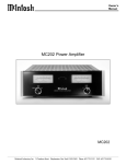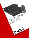
1
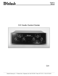
MA6400
INTEGRATED
AMPLIFIER
MA6400
INTEGRATED
AMPLIFIER
IMPORTANT
SAFETY
INSTRUCTIONS
THESE
INSTRUCTIONS
ARE TO PROTECT
YOU AND THE
MclNTOSH
INSTRUMENT.
BE SURE TO
FAMILIARIZE
YOURSELF
WITH THEM
1.
2.
3.
4.
5.
6.
7.
8.
9.
10.
11.
12.
13.
14.
15.
16.
17.
Read all instructions - Read the safety and operating instructions before operating the instrument.
Retain Instructions - Retain the safety and operating instructions for future reference.
Heed warnings - Adhere to warnings and operating instructions.
Follow Instructions - Follow all operating and use instructions.
WARNING: TO REDUCE RISK OF FIRE OR ELECTRICAL SHOCK, DO NOT EXPOSE
THIS INSTRUMENT TO RAIN OR MOISTURE.
Power Sources - Connect the power supply only to the type described in the operating instructions
or as marked on the unit.
Power Cord Protection - Route power supply cords so that they are not likely to be walked on or
pinched by items placed upon or against them, paying particular attention to cords at plugs,
convenience receptacles, and the point where they exit from the instrument.
Ventilation - Locate the instrument for proper ventilation. For example, the instrument should not be
placed on a bed, sofa, rug, or similar surface that may block ventilation openings; or, placed in a builtin installation, such as a bookcase or cabinet, that may impede the flow of air through the ventilation
openings.
Heat - Locate the instrument away from heat sources such as radiators, heat registers, stoves, or
other appliance (including amplifiers) that produce heat.
Wall or Cabinet Mounting - Mount the instrument in a wall or cabinet only as described in the owner's
manual.
Water and Moisture - Do not use the instrument near water - for example, near a bathtub, washbowl,
kitchen sink, laundry tub, in a wet basement or near a swimming pool, etc.
Cleaning - Clean the instrument by dusting with a dry cloth. Clean the panel with a cloth moistened
with a window cleaner.
Object and Liquid Entry - Do not permit objects to fall and liquids to spill into the instrument through
enclosure openings.
Nonuse Periods - Unplug the power cord from the AC power outlet when left unused for a long period
of time.
Damage Requiring Service - Service must be performed by qualified service personnel when:
A. The power supply cord or the plug has been damaged; or
B. Objects have fallen, or liquid has been spilled into the instrument; or
C. The instrument has been exposed to rain; or
D. The instrument does not appear to operate normally or exhibits a marked change in performance or
E. The instrument has been dropped, or the enclosure damaged.
Servicing - Do not attempt to service beyond that described in the operating instructions. All other
should be referred to qualified service personnel.
Grounding or Polarization - Do not defeat the inherent design features of the polarized plug. Nonpolarized line cord adapters will defeat the safety provided by the polarized AC plug.
C A U T I O N : TO PREVENT ELECTRICAL SHOCK DO NOT USE THIS (POLARIZED)
PLUG WITH AN EXTENSION CORD, RECEPTACLE OR OTHER OUTLET UNLESS THE
BLADES CAN BE FULLY INSERTED TO PREVENT BLADE EXPOSURE.
A T T E N T I O N : POUR PEVENIR LES CHOCS ELECRIQUES PAS UTILISER CETTE
FICHE POLARISEE AVEC UN PROLONGATEUR, UNE PRISE DE COURANT OU UNE
AUTRE SORTIE DE COURANT, SAUF SI LES LAMES PEUVENT ETRE INSEREES A
FOND SANS EN LAISSER AUCUNE PARTIE A DECOUVERT.
The lightning flash with arrowhead, within an equilateral triangle, is intended to alert the user
to the presence of uninsulated "dangerous voltage" within the product's enclosure that may
be of sufficient magnitude to constitute a risk of electric shock to persons.
CAUTION: TO PREVENT THE RISK OF ELECTRIC SHOCK, DO
NOT REMOVE COVER (OR BACK). NO USER-SERVICEABLE PARTS
INSIDE. REFER SERVICING TO QUALIFIED PERSONNEL.
The exclamation point within an equilateral triangle is intended to alert the user to the
presence of important operating and maintenance (servicing) instructions in the literature
accompanying the appliance.
04027100
BE082006
WARNING: THIS UNIT IS CAPABLE OF PRODUCING HIGH SOUND
PRESSURE LEVELS. CONTINUED EXPOSURE TO HIGH SOUND
PRESSURE LEVELS CAN CAUSE PERMANENT HEARING IMPAIRMENT
OR LOSS. USER CAUTION IS ADVISED AND EAR PROTECTION IS
RECOMMENDED WHEN PLAYING AT HIGH VOLUMES.
2
Your decision to own this piece of Mclntosh Stereo Equipment ranks you at the very top
THANK
YOU
among discriminating music listeners. You now have "The Best." The Mclntosh dedication to
"Quality." is assurance that you will receive many years of musical enjoyment from this unit.
Please take a short time to read the information in this manual. We want you to be as familiar
as possible with all the features and functions of your new piece of Mclntosh equipment. This
will ensure that you receive all the performance benefits this instrument can offer you, and that
it will become a highly valued part of your home entertainment system.
The serial number, purchase date, and Mclntosh Laboratory Service contract number
are important to you for possible insurance claim or future service. Record this information here.
Serial Number
Purchase Date
Service Contract Number
SERVICE CONTRACT
4
INTRODUCTION
5
HOW TO INSTALL THE MA6400
5
FRONT PANEL CONTROLS SWITCHES AND PUSHBUTTONS
HAND HELD REMOTE CONTROLLER
THE REAR PANEL AND HOW TO MAKE CONNECTIONS
HOOKUP DIAGRAM
TECHNICAL DESCRIPTION
SPECIFICATIONS
10,
TABLE OF
CONTENTS
6, 7. 8. 9
11, 12
13, 14, 15, 16, 17
18
19. 20, 21, 22
23, 24
CUSTOM INSTALLATION DIAGRAM
25
RECOMMENDED VENTILATION CUTOUT
25
3
TAKE ADVANTAGE OF 3 YEARS OF CONTRACT SERVICE. . .
FILL IN THE APPLICATION NOW.
Your C39 Audio/Video Control Center will give you many years of satisfactory performance.
If you have any questions, please contact,
Mcintosh Laboratory Inc.
2 Chambers Street
Binghamton, New York 13903-2699
Phone: 607-723-3512
MclNTOSH
THREE YEAR
SERVICE
CONTRACT
An application for A THREE YEAR SERVICE CONTRACT is included with this manual.
The terms of the contract are:
1. If the instrument covered by this contract becomes defective, Mcintosh will provide all parts,
materials, and labor needed to return the measured performance of the instrument to the
original performance limits free of any charge. The service contract does not cover any
shipping costs to and from the authorized service agency or the factory.
2. Any Mcintosh authorized service agency will repair all Mcintosh instruments at normal
service rates. To receive the free service under the terms of the service contract, the service contract certificate must accompany the instrument when taken to the service agency.
3. Always have service done by a Mcintosh authorized service agency. If the instrument is
modified or damaged as a result of unauthorized repair the service contract will be cancelled. Damage by improper use or mishandling is not covered by the service contract.
4. The service contract is issued to you as the original purchaser. To protect you from
misrepresentation this contract cannot be transferred to a second owner.
5. Units in operation outside the United States and Canada are not covered by the Mcintosh
Factory Service Contract, irrespective of the place of purchase. Nor are units acquired
outside the USA and Canada, the purchasers of which should consult with their dealer
to ascertain what, if any, service contract or warranty may be available locally.
4
The Mclntosh MA6400 is an Integrated Amplifier with 100 watts per channel, combined with
INTRODUCTION
a full featured remote controlled Preamplifier.
The MA6400 includes the popular Mclntosh features such as POWER GUARD, DC output
protection, thermal protection and Sentry Monitor protection circuits. Front panel power guard
indicators are included for each channel. Large illuminated front panel power level meters read
the power output of each channel to a high degree of accuracy.
The Preamplifier section can accommodate seven high level signal sources, or six high level
and one magnetic phono. All switching functions are performed with digital logic integrated
circuits driving ultra reliable, low distortion Electromagnetic switches. Bass and Treble controls
as well as an active Loudness control give the listener a wide range of options to shape the
frequency response to optimum for any listener preferences. All the circuit elements for these
controls are removed from the circuit path when the controls are in their flat settings. Rear panel
signal processor connections can be switched in or out of the circuit with a convenient switch.
Other features include two Tape Monitor switches, two Tape Copy switches and a
Headphone jack for private listening. The MA6400 can be muted with the Hand Held Remote
Controller. Refer to the Manual section TECHNICAL DESCRIPTION for further circuit and feature
information.
The MA6400 can be installed upright on a table or shelf, standing on its own plastic feet. It
INSTALLATION
can also be custom installed in furniture or cabinet of your choice. The required panel cutout
and unit dimensions are shown on a page near the back of this manual. Always provide
adequate ventilation for your MA6400. Cool operation insures the longest possible operating life
for any electronic instrument.
A custom cabinet installation should provide the following recommended minimum spacing
dimensions to insure adequate ventilation and cooling. Allow at least 1-1/2 inches (3.8cm) above
the unit so airflow is not obstructed. Allow at least 17-1/2 inches (44.5cm) behind the mounting
panel, which includes clearance for connectors. Allow 1-1/8 inches (2.9cm) in front of the
mounting panel for knob clearance.
In a custom cabinet Installation, It Is essential that the specified cutout be made In the
mounting shelf below the rear heat sink section of the MA6400 for adequate convection
cooling.
5
FRONT PANEL
CONTROLS,
SWITCHES AND
PUSHBUTTONS
The MA6400 can be remotely controlled. Most of the operating functions performed at
the front panel, also can be done by the MA6400 Hand Held Remote Controller. The
following Information refers only to the front panel. Other sections of this manual explains
the functions and operation of the MA6400 Hand Held Remote Controller and the rear
panel connections.
The last page of this manual folds out to show drawings of the front and rear panels of
the MA6400. This will help you In Identifying and locating the front panel controls,
switches, pushbuttons and the rear panel connectors and switches. The letters and
numbers on the drawings refer to the Information that follows.
A. BASS AND TREBLE
Provides 12dB boost and cut. with neutral flat response at the center detent position. The
Bass and Treble controls affect the SPEAKERS 1 and 2, MAIN OUTPUTS and the HEAD¬
PHONES. The TAPE 1 and TAPE 2 OUTPUTS are not affected by the Bass and Treble controls.
B. WATTS POWER OUTPUT
Two illuminated WATT meters are provided on the MA6400 front panel. The meters are peak
responding and their circuits are constantly reading the output power required by the musical
information.
One additional calibration mark above 100 watts is on the meters. This mark is 200 watts,
(+3dB). The amplifier cannot produce a continuous 200 watts of power, but can produce well
above 100 watts on program peaks, especially into lower impedance loads.
The upper scale on the meters is calibrated in average watts power, and the lower scale in
decibels. The meter calibration lines reading from right to left, starting at the 100 watt indication
are as follows.
100
Watts Indicated
40
20
10
Wans indicated
4
2
1
Watts Indicated
0.4
0.2
0.1
Watts Indicated
0.04
0.02
0.01
0.004
0.002
6
Watts indicated
C. POWER GUARD
FRONT PANEL
CONTROLS,
SWITCHES AND
PUSHBUTTONS
Both channels of the MA6400 incorporate the Mclntosh POWER GUARD circuit which
prevents output clipping with its harsh and damaging distortion. A front panel LED Power Guard
indicator is provided for each of the channels. The LED lights whenever the Power Guard circuit
is activated for that channel. This indicates that the amplifier is producing its maximum
undistorted power output, and that you are being protected from overdrive and clipping. The
output level where Power Guard acts will be well above the rated power due to conservative
Mclntosh design philosophy.
(If the POWER GUARD indicators turn on and stay on continuously for either channel, it
indicates a problem is present. If this condition occurs, contact your Mclntosh dealer for
assistance.)
D. VOLUME / (MUTE LED)
VOLUME adjusts the volume level for the SPEAKERS 1 and 2 outputs, MAIN outputs and the
HEADPHONES. The TAPE 1 and 2 OUTPUTS are not affected by the VOLUME control.
A Red MUTE LED Just to the right of the VOLUME control turns ON to indicate the MA6400
output is MUTED. Activate the MUTE mode by pressing the MUTE pushbutton on the Hand Held
Remote Controller. Press MUTE again, press an UP or DOWN VOLUME pushbutton or press an
Input pushbutton to restore normal operation. Mute affects the SPEAKERS 1 and 2 and the MAIN
OUTPUTS. The TAPE 1 and 2 OUTPUTS and the HEADPHONES are not affected by MUTE.
E. LOUDness-BALANCE
BALANCE control, (large outer knob): Adjusts the volume of the Left and Right channels
relative to each other. The BALANCE control affects only the SPEAKERS 1 and 2 outputs, the
MAIN outputs and the HEADPHONES. The TAPE 1 and 2 OUTPUTS are not affected by the
BALANCE control.
L, (Left): Turn the control to the left to accent the left channels by reducing the volume of the
right channels.
R, (Right): Turn the control to the right to accent the right channels by reducing the volume
of the left channels
LOUDness control, (small inner knob): Provides frequency response contoured to
compensate for the behavior of the human ear at softer listening levels. At the fully
counterclockwise detent position, the frequency response is perfectly flat and the loudness
circuit components are removed from the signal path. Turn the control clockwise to modify the
frequency response in the correct proportion required for softer listening levels. The
compensated frequency response is not affected by changes in the volume control settings.
First adjust the VOLUME Control for the desired listening level, then adjust the LOUDness
Control to the setting you personally prefer.
7
FRONT PANEL
CONTROLS,
SWITCHES AND
PUSHBUTTONS
The LOUDness control affects the SPEAKERS 1 and 2 outputs, the MAIN OUTPUTS and the
HEADPHONES. The TAPE 1 and 2 OUTPUTS are not affected by the LOUDness control.
F. IR SENSOR WINDOW
The IR (Infrared) sensor that accepts IR signals from the MA6400 Hand Held Remote
Controller.
G. TAPE MONitor 1 and 2
Press TAPE MON 1 or 2 to listen to playback of tapes from either of two tape recorders. You
can listen to previously recorded tapes, or monitor tape from a three-head tape recorder during
the recording process. The TAPE MON pushbuttons operate independently from the INPUT
switch. A Red LED will turn ON above either pushbutton to indicate which TAPE MONitor has
been selected.
H. TAPE COPY, 1
2, 2 1
Copy tapes from either of two tape recorders, to the other. The TAPE COPY pushbutton
switches operate independently from the INPUT switch. Use the TAPE MONitor switches to
monitor the output of the recorder playing the original tape, or the recorder making the copy.
A Red LED will turn ON above either pushbutton to indicate which TAPE COPY mode is in use.
The TAPE COPY switches are electronically interconnected to prevent both circuits from
being activated at the same time. If you press one of the TAPE COPY switches to activate a
copy function, you must press the same TAPE COPY switch again before pressing the other
TAPE COPY switch.
I. HEADPHONES
Plug in a pair of dynamic headphones to this jack for headphone listening. Press MUTE on
the MA6400 Remote Controller to mute the SPEAKERS 1 and 2 outputs and the MAIN OUTPUTS
to allow private headphone listening. MUTE does not affect the HEADPHONES or the TAPE 1
and TAPE 2 OUTPUTS.
An alternate method for private headphone listening is to turn off both SPEAKERS 1 and 2
with the front panel SPEAKERS switches.
J. (INPUT SELECTOR)
Selects any of the five high level inputs, (or the phono input), that will appear at the
SPEAKERS 1 and 2 outputs. MAIN OUTPUTS and the HEADPHONES. The selected signal will
also appear at the TAPE 1 and 2 OUTPUTS.
K. MONO
Press the MONO pushbutton to combine the left and right channels for MONO operation at
8
the SPEAKERS 1 and 2 outputs, the MAIN OUTPUTS and the HEADPHONES. A Red LED above
FRONT PANEL
CONTROLS,
SWITCHES AND
PUSHBUTTONS
the pushbutton will turn ON to indicate the MONO mode of operation. The MONO pushbutton
does not affect the TAPE 1 and 2 OUTPUTS. They are always stereo.
L. 1 SPEAKERS 2
Select SPEAKERS 1. SPEAKERS 2. or both pairs of speakers simultaneously. A Red LED
above each SPEAKERS pushbutton lights to indicate which Speakers are turned ON. The
SPEAKERS pushbuttons do not affect the MAIN OUTPUTS, the HEADPHONES or the TAPE 1
and 2 OUTPUTS.
SPEAKERS 1 usually is used for the loudspeakers in the main listening area. SPEAKERS 2
can be used for loudspeakers in a remote area. Add a WK-2 keypad or In-wall IR sensor in the
remote area. You can then select the program source and volume level in the remote area with
the keypad or with the MA6400 Hand Held Remote Controller. (The same program source and
volume level will also be present in the main listening area loudspeakers if they are selected.)
M. POWER
Press the red POWER button to turn the MA6400 system ON. Press again to turn it OFF. The
rear panel SWITCHED AC Outlet turns ON and OFF with the POWER switch. The RED LED
above the POWER switch stays ON continuously whenever the MA6400 is connected to a live
AC outlet. This is an indication that the backup power supply is on. This allows you to turn on the
MA6400 with the Hand Held Remote Controller.
9
MA6400
HAND HELD
REMOTE
CONTROLLER
The descriptions and functions of the MA6400 Remote Controller pushbuttons refer to the
numbers on the drawings. Several operating functions are designed to be used when the
optional RCT-2 Remote Control Translator is added to the MA6400. The RCT-2 is a learning
device which allows the MA6400 to remotely control other brands of compatible accessories.
SPECIAL NOTE:
The pushbuttons marked In black do not function with the MA6400. They function only
when this Remote Controller Is used with another Mclntosh model.
1. Select input signals for CD1, CD2. TUNER. PHono/AUX or VIDEO.
2. Press MON 1 or MON 2. (Tape Monitor), to listen to playback of tapes from either of two tape
recorders. You can listen to previously recorded tapes, or monitor tape from a three-head tape
recorder during the recording process. A Red LED will turn ON above either of the MA6400
front panel pushbuttons to indicate whether (Tape) MON 1 or MON 2 has been selected.
3. Select additional audio/video program signal sources when the optional MVS-3 Audio/Video
Selector is added to the MA6400 system. First press the Remote Controller VIDEO pushbutton
and then within 3 seconds, press the desired pushbutton for any of the five audio/video signal
sources connected to the MVS-3.
4. Select Mclntosh CD Player or CD Changer operating functions.
Using a Mclntosh SINGLE DISC CD PLAYER. STOP. BACK TRACK (
), NEXT TRACK ( )
and PLAY functions can be performed..
Using a Mclntosh CD CHANGER. STOP. BACK TRACK (
), NEXT TRACK (
) and PLAY
functions can be performed while a disc is playing.
When the CD changer is In the STOP position, BACK TRACK (
and NEXT TRACK (
) selects the SINGLE DISC
) selects which of the other six discs you wish to play. After pressing
STOP, the first time you press NEXT (
), disc number 1 is selected. Press again as desired to
select discs 2 through six.
FOR EXAMPLE: To select disc number 6 from the single disc play mode, press STOP and
then NEXT ( ) six times. To select disc number 2, press STOP and then press NEXT ( ) twice.
To select the disc in the SINGLE disc slot, press STOP and then press BACK (
) once.
If the optional Mclntosh RCT-2 Remote Control Translator is used with the MA6400, these
pushbuttons could operate another brand CD player or a tape recorder.
5. Press the SYS OFF pushbutton to turn the entire MA6400 system OFF.
10
MA6400
HAND HELD
REMOTE
CONTROLLER
6. Press the POWER pushbutton to turn the MA6400 system ON. Press again to turn the system
OFF.
7. The ACC (Accessory) ON or OFF pushbuttons function when the optional RCT-2 Remote
Control Translator is being used with the MA6400. They can be programmed to turn on and off
the AC power of an accessory component.
(Pushbuttons listed under Number 8 and Number 9 function when a compatible Mclntosh
Tuner such as the MR7084 Is connected to the MA6400.)
8. Press one of the numbered pushbuttons to select Tuner Station presets.
9. Select the Tuner functions AM, FM, REVIEW, SEEK UP or SEEK DOWN. (These tuner
operating functions apply to the Mclntosh MR7084 Tuner, with a DATA cable connected from
the MA6400 TUNER DATA PORT to the MR7084 DATA IN. A DATA cable uses single conductor
11
MA6400
HAND HELD
REMOTE
CONTROLLER
cable with 1/8 inch mini phone plugs on each end. Connections are to the Tip (+) and Sleeve
(-) of the plug.)
Press REVIEW to start the automatic 3 second audition of each of the stations stored in the
tuner preset memory. Press REVIEW again to stop on the desired preset. Cancel the automatic
REVIEW process by pressing REVIEW a second time, or pressing any other Tuner function
pushbutton.
SEEK UP (
) or SEEK DOWN (
) cycles tuning through all station frequencies.
10. Press SPKR 1 or SPKR 2 to select either pair of loudspeakers or both pairs simultaneously.
11. E (ENTER) is used with the optional RCT-2 Remote Control Translator to operate accessory
equipment.
12. Press MUTE to mute SPEAKERS 1 and 2 and the MAIN OUTPUTS. MUTE does not affect
TAPE 1 and 2 OUTPUTS or HEADPHONES. A Red LED to the right of the front panel volume
control turns ON to indicate that the outputs are muted. Press MUTE a second time, press UP
or DOWN VOLUME, or press another input pushbutton to restore normal operation.
13. Press UP ( ) VOLUME to raise the listening volume and DOWN ( ) VOLUME to lower the
listening volume. The TAPE 1 and 2 OUTPUTS are not affected by the remote VOLUME
pushbuttons
HOW TO INSTALL BATTERIES IN THE
MA6400 HAND HELD REMOTE CONTROLLER
Slide open the battery compartment. Insert two type AAA batteries into the compartment,
making sure to observe the battery polarities indicated in the battery compartment.
When the batteries are nearing exhaustion, the effective range of the remote controller
decreases, and MAY even fail to operate. In this case, replace both batteries with fresh ones.
NOTE:
1. Do not mix old and new batteries. Use ONLY batteries that are new.
2. Make sure both batteries are of the same type and identical.
3. To prevent damage caused by possible battery leakage, remove the batteries from the
remote controller if it is not going to be used for an extended period of time.
4. Never dismantle batteries or dispose of them in a fire, as they may explode. Dispose of old
batteries in an approved method for proper safety.
12
Use high quality cables to Interconnect the accessory equipment used with your
MA6400. This will ensure the best possible overall performance from your stereo system.
Your Mclntosh dealer can advise you on the type and length of cables best suited for your
specific Installation.
To minimize the possibility of hum pickup or Interference, locate the cables away from
AC power cords or loudspeaker cables.
1. CD1 CONTROL
Connect a Mclntosh CD control cable from the CD1 CONTROL connector to a matching
connector on a Mclntosh CD player or changer. This allows you to control CD player functions
with the MA6400 Hand Held Remote Controller transmitting to the MA6400 IR sensor.
A CD Control cable is included with each Mclntosh CD player or changer.
2. DATA PORTS
The DATA PORTS provide data signals to be fed to compatible audio and video accessory
components. This allows you to control the accessory components with their own remote
controllers transmitting to the MA6400 IR sensor.
The SUM DATA port is used for connecting to the optional Mclntosh Model RCT-2 Remote
Control Translator. Any IR signal transmitted to the MA6400 sensor results in data signals at this
port. The RCT-2 is a learning device that will allow the MA6400 to remotely control most major
brands of accessory components.
The VIDEO DATA port connects to the optional Mclntosh MVS-3 Audio/Video Selector. This
allows the MA6400 to select and switch up to five Audio/Video signal sources and a TV monitor
connected to the MVS-3.
All cables connected from the DATA ports use single conductor shielded wire with 1/8"
mini phone plugs. Connections are to the tip (+) and sleeve (-) of the plug. (Mclntosh Part
No. 170-202.)
3. PWR AMP IN (Left and Right); PWR AMP INPUT/ EXTernal-INTemal (Switch)
Set the PWR AMP INPUT switch to EXT to allow an external signal source or preamplifier to
feed signals directly to the MA6400 power amplifier section through the PWR AMP IN
connectors. This feature also allows you to add an additional signal processor or equalizer to
the MA6400 system. When the PWR AMP INPUT switch is in the EXT setting, the MA6400
preamplifier and power amplifier sections are disconnected from each other and are completely
independent. When the switch is set to the INT position, the MA6400 preamplifier section feeds
signals directly to the internal power amplifier section.
4. MAIN OUTPUTS
Connect cables from the MAIN OUTPUTS to the inputs of an external power amplifier. This
allows the MA6400 to feed signals simultaneously to both the internal power amplifier as well as
an external power amplifier. If you wish to use the MA6400 preamplifier independently to feed
13
THE REAR PANEL
AND HOW
TO MAKE
CONNECTIONS
THE REAR PANEL
AND HOW
TO MAKE
CONNECTIONS
signals only to an external power amplifier or accessory, set the PWR AMP IN to the EXT
position. When the switch is set to the INT position, the MA6400 preamplifier section feeds
signals directly to the internal power amplifier section.
5. TAPE 1 and TAPE 2 OUTPUTS
These outputs provide signals to feed two separate tape recorders. The program that
appears at the tape outputs is determined by the setting of the front panel Input Selector switch.
The TAPE COPY Switches also affect the signals at the TAPE OUTPUTS.
Connect a cable from the MA6400 Left channel TAPE 1 OUTPUT to the left channel high level
input of a tape recorder. Connect a cable from the MA6400 Right channel TAPE 1 OUTPUT to
the right channel high level input of the tape recorder. Connect a second tape recorder in a
similar manner, to the TAPE 2 OUTPUTS.
6. PROCESSOR FROM and TO
An external signal processor can be added to the MA6400 that will affect only the SPEAKERS
1 and 2. MAIN OUTPUTS and the HEADPHONES. The PROCESSOR circuits are activated
when the PROCESSOR IN-OUT switch is set to the IN position.
When an external processor is properly connected, the program signals feed to the
processor from the PROCESSOR-TO jacks, and return to the MA6400 at the PROCESSORFROM jacks.
Connect a cable from the MA6400 left channel PROCESSOR-TO jack to the signal processor
left channel input. Connect a cable from the MA6400 right channel PROCESSOR-TO jack to the
right channel signal processor input.
Connect a cable from the left channel processor output to the MA6400 left channel
PROCESSOR-FROM jack. Connect a cable from the right channel processor output to the
MA6400 right channel PROCESSOR-FROM jack.
WHEN AN EXTERNAL SIGNAL PROCESSOR IS CONNECTED TO THE MA6400
PROCESSOR JACKS, AND THE PROCESSOR SWITCH IS SET TO IN, THE PROCESSOR
MUST BE TURNED ON AND OPERATING, OR IN BYPASS MODE, FOR A PROGRAM TO BE
HEARD THROUGH THE SYSTEM.
IF AN EXTERNAL SIGNAL PROCESSOR IS NOT BEING USED, SET THE PROCESSOR
SWITCH TO OUT.
7. TAPE 1 and 2 INPUTS
Connect a cable from the left channel output of a tape recorder to the MA6400 L (Left)
channel TAPE 1 INPUT. Connect a cable from the right channel output to the corresponding R
(Right) TAPE 1 INPUT. Connect a second tape recorder in a similar manner to the TAPE 2
INPUTS.
The TAPE INPUTS can also be used for other accessory equipment with similar output levels.
14
8. VIDEO
Use these inputs for the audio signals from accessories such as a Laser Disc Player. VCR,
or TV receiver.
Connect a cable from the left channel audio output of the video unit to the MA6400 L (Left)
channel VIDEO INPUT. Connect a cable from the right channel audio output of the video unit
to the MA6400 R (Right) VIDEO INPUT.
Use the VIDEO input when an optional MVS-3 Audio/Video Selector is added to the MA6400.
This allows you to switch up to five Audio/Video signal sources and a TV monitor connected to
the MVS-3. The MVS-3 must also be connected to the MA6400 VIDEO DATA PORT.
9. TUNER
Connect cables from the left and right channel outputs of a tuner to the MA6400 L (Left) and
R (Right) TUNER INPUTS. A Mclntosh MR7084 can be connected to the MA6400 and operated
by the MA6400 Remote Controller. This feature requires a Data cable to be connected from the
MA6400 TUNER DATA port to the MR7084 DATA IN port.
(A Data cable consists of a single conductor shielded wire with 1/8 inch mini phone plugs on
each end. Connections are to the Tip (+) and sleeve (-) of the plug. Mclntosh Part No. 170-202.)
10. CD1 and CD2
Connect a cable from the left channel output of a CD player to the MA6400, L (Left) CD1
INPUT. Connect a cable from the right channel output to the MA6400, R (Right) CD1 INPUT.
Connect a second CD player to the MA6400 CD2 inputs in a similar manner.
For example, CD1 inputs could be used for a single play CD player, and the CD2 inputs for
a CD changer.
Connect a Mclntosh CD Control Cable between a Mclntosh CD unit and the MA6400 CD1
CONTROL connector. This allows a Mclntosh CD player or changer connected to CD1
Inputs to be operated by the MA6400 Hand Held Remote Controller.
11./12./13. AUX (Auxiliary); PH (Phono); AUX-PH SELECTOR (Switch); GND
Both the PHono and Auxiliary input jacks are selected by the same position on the front
panel Input Selector switch. One or the other pair of inputs can be used, but not both
simultaneously.
To use AUX INPUTS
Connect the left channel high level output of any audio accessory unit to the MA6400 L (Left)
Auxiliary INPUT. Connect the right channel accessory output to the MA6400 R (Right) Auxiliary
INPUT. Set the AUX-PH SELECTOR to the AUX position. (The Phono Inputs are not active in this
operating mode.)
To use Phono INPUTS
Connect a cable from the left channel turntable output to the MA6400 L (Left) PHono INPUT.
15
THE REAR PANEL
AND HOW
TO MAKE
CONNECTIONS
THE REAR PANEL
AND HOW
TO MAKE
CONNECTIONS
Connect a cable from the right channel turntable output to the MA6400 R (Right) PHono INPUT.
Set the AUX-PH SELECTOR to the PH position. (The AUX inputs are not active in this operating
mode.)
The MA6400 phono input circuit is designed to accept the signals from a standard moving
magnet phono cartridge. The input impedance is 47K ohms and 65pF capacitance.
GND (Ground)
If there is a separate ground wire from the turntable, connect it to the GND terminal.
14. 5A-250V SLO-BLO (Fuse)
Caution: For continued protection against fire hazard, replace only with the same type 5A250V SLO-BLO fuse.
15. (POWER CORD)
Connect the MA6400 Power Cord to a 120 volt, 50/60Hz AC wall outlet.
CAUTION FOR UNITS WITH A POLARIZED POWER PLUG:
TO PREVENT ELECTRIC SHOCK, DO NOT CONNECT THE POLARIZED AC PLUG ON
THIS UNIT TO AN EXTENSION CORD OR OTHER AC OUTLET THAT IS NOT DESIGNED TO
ACCEPT POLARIZED PLUGS. THE PLUG MUST BE FULLY INSERTED TO PREVENT
BLADE EXPOSURE AND MAINTAIN LINE POLARITY.
If your MA6400 Is configured for a specific power line voltage necessary for your
particular geographic location, connect the Power Cord to the appropriate outlet. The
lettering above the Power Cord outlet on the back panel of your MA6400 will list the
voltage requirements for your particular unit.
16. UNSWITCHED AC RECEPTACLE
This AC receptacle will stay on at all times as long as the MA6400 power cord is connected
to a live 120V, 50/60Hz power outlet. For example, this outlet could be used for a VCR that is
programmed to record a TV show when the main stereo system is turned off.
17. SWITCHED AC RECEPTACLE
One AC receptacle is provided for accessory equipment. This receptacle turns on and off
with the MA6400 Power switch.
THE TOTAL POWER CONSUMPTION OF ALL THE ACCESSORIES CONNECTED TO THE
MA6400 BACK PANEL OUTLETS MUST NOT EXCEED 11.6 AMPERES OR 1400 WATTS.
16
The 120 volt AC current switching capabilities of the MA6400 can be Increased by
adding an optional Mclntosh R612A or PC-2 Power Control Relay.
18. SPEAKERS 1 - SPEAKERS 2
Connect two pairs of loudspeakers to the SPEAKERS 1 and SPEAKERS 2 terminals. Make
sure that the speaker plus and minus. (Hot and Common) terminals are connected to the
corresponding plus (+) and minus (-) amplifier terminals.
The HOT and COMMON ( + and -) terminals of both pairs of speakers must be connected
in an identical manner to the proper amplifier output terminals so the speakers will operate IN
PHASE. This means that the speaker driver surfaces move back and forth the same in each
speaker system. Almost all loudspeaker systems have their hot and common terminals color
coded, with red usually as hot or plus and black as common or minus. The output signals of all
Mclntosh power amplifiers are always IN-PHASE with the input signals.
Use high quality speaker cables since this is an important link in your stereo system.
Selection of the proper size and type of speaker cable is necessary for you to receive the best
possible performance from your amplifier and speaker combination. Consult your Mclntosh
dealer for recommendations on the cables that will best fit the needs of your stereo installation.
19. EXTernal SENSOR
Connect a coaxial cable, (RG6 or RG59U), from the EXTernal SENSOR connector to a WK-2
keypad or an R649 wall mounted IR Sensor. This allows the MA6400 Hand Held Remote
Controller to send control signals to the MA6400 without aiming it at the front panel.
One example of a need for this feature would be if the MA6400 were installed behind a
cabinet door that would block the front panel IR sensor.
Another use for this feature is to place a keypad or sensor in the remote area where a second
pair of loudspeakers is installed. You can select program sources and control volume in the
remote area. (The same program source and volume level will also be present in the main
listening area loudspeakers if they are selected.)
20. PWR CTL (Power Control)
This connector supplies a control signal that will turn ON or OFF the AC power of an
accessory component with a Power Control Input connector.
A Power Control cable uses single conductor shielded wire with 1/8" mini phone plugs
on each end. Connections are to the tip (+) and sleeve (-) of the plug.
(Mclntosh Part No. 170-202.)
17
THE REAR PANEL
AND HOW
TO MAKE
CONNECTIONS
HOOKUP
DIAGRAM
18
DESIGN PHILOSOPHY
The design philosophy incorporated in the MA6400 involved many different techniques, all
based on sound scientific logic. Every stage of voltage or current amplification is designed to
be as linear as possible. Negative feedback is then utilized to enhance the performance.
Mclntosh engineers know how to properly design negative feedback circuits so they contribute
to the extremely low distortion performance expected from a Mclntosh amplifier. The typical
Mclntosh owner would never accept the approximately 100 times higher distortion of many so
called non- feedback designs.
All transistors are selected to have nearly constant current gain (Beta) over the entire current
range they must cover. Output transistors in particular, must have matched uniform current
gain, high current-bandwidth product and large active region safe operating area.
Resistors and capacitors in the signal path are carefully selected to have exceedingly low
voltage coefficients, (change of resistance or reactance with applied voltage). Precision metal
film resistors, low dielectric absorption film capacitors and premium audio grade electrolytics
are used in all critical circuit locations.
PROTECTION CIRCUITS
Some power amplifier manufacturers claim that their products do not need or do not use
protection circuits and that such circuits compromise performance. Mclntosh feels that
protection circuits are desirable and necessary to prevent amplifier or loudspeaker damage due
to abnormal circumstances. The genius of Mclntosh engineering has resulted in protection
circuits which do not effect or compromise the normal performance of a power amplifier.
Five different types of protection circuits are incorporated in the MA6400 to insure it a long,
safe and trouble free operating life. This is just one of the characteristics of Mclntosh power
amplifiers that have made them world famous. The SENTRY MONITOR circuit is a good example.
SENTRY MONITOR CIRCUIT
All power transistors have limits for the maximum amount of power they can handle. The
MA6400 output transistors and power supply have been designed to allow very high current flow
into properly matched load impedances. However, if a short circuit or very low load impedance
were connected to the MA6400 outputs, destructive current levels could be reached if it was not
controlled by the Mclntosh SENTRY MONITOR circuit. This circuit senses the dynamic operating
time, voltage and current of the output stage, and controls it to safe operating limits. The
SENTRY MONITOR circuit does not limit the power output available from the amplifier.
There is absolutely no compromise in sonic performance and it ensures safe operation of the
amplifier under even the most extreme operating conditions.
THERMAL CONTROL
All power transistors have limits to the maximum amount of heat they can safely tolerate. The
MA6400 uses highly efficient amplifying circuits which produces relatively little heat from the
19
TECHNICAL
DESCRIPTION
TECHNICAL
DESCRIPTION
power transistors for the output power produced. The amplifier uses large area heat sinks to
efficiently dissipate the transistor heat. Natural convection air flow is sufficient for safe cool
operation.
If the cooling air is blocked, or the amplifier operating temperature is forced too high, thermal
sensors will turn off the speaker relays. When the problem is corrected and the amplifier cools
to its normal operating temperature, the speaker relays will turn back on.
POWER GUARD
The MA6400 includes the unique patented Mclntosh POWER GUARD circuit on each
channel. POWER GUARD eliminates the possibility of ever over driving the amplifier into
clipping. Clipping occurs when an amplifier is overdriven past its output design capabilities. An
overdriven amplifier can produce both audible and ultrasonic distortion levels approaching
40%. The audible distortion is certainly unpleasant, but the ultrasonic distortion is also
undesirable, since it can damage tweeter loudspeakers. The Mclntosh POWER GUARD circuit
acts as a waveform comparator, monitoring both the input and output signal waveforms. Under
normal operating conditions there are no differences between these waveforms. When an
amplifier is overdriven beyond its maximum distortion free output, there will be a difference
between the two signal waveforms. If the difference exceeds 0.3% (equivalent to 0.3% harmonic
distortion), the amber POWER GUARD indicator will light. If the difference continues to increase,
the POWER GUARD circuit controls an electronic attenuator at the input of the amplifier to
reduce the gain just enough to prevent any further increase in distortion. Distortion will not
exceed 2% with as much as 14dB overdrive. Without POWER GUARD, the distortion could
easily reach 40% for the same operating conditions.
A Mclntosh power amplifier with POWER GUARD will always deliver its maximum distortion
free output. This power is always well above the rated power due to the Mclntosh philosophy
of conservative design. You will never experience the harsh and damaging distortion due to
clipping when using a Mclntosh MA6400 amplifier with POWER GUARD.
LOGIC DRIVEN CONTROL
All Inputs, Outputs, CD, and Data Ports are controlled by logic circuits in the MA6400. This
logic is changed by front panel switches or by the microprocessor IR decoder. This
microprocessor is programmed with exclusive Mclntosh software. It receives data from the
MA6400 front panel IR sensor and provide the command signals for all switching functions. A
second microprocessor decodes the CD1 Control commands.
The logic circuits activate Electro-Magnetic switches for the final step in all signal switching.
ELECTRO-MAGNETIC SWITCHING
All signal switching in the MA6400 is done by ELECTRO-MAGNETIC methods. ELECTRO¬
MAGNETIC switching is an old an proven technology that has been upgraded with modern
materials and manufacturing techniques.
20
Each switch consists of a sealed glass tube filled with an inert oxygen free atmosphere. Tiny
connecting leads protrude from either end. These leads extend into the tube and overlap one
another with a separation of a few thousandths of an inch. The leads are made from a ferrous
material that is influenced by a magnetic field. They are first plated with gold as a base material,
then with rhodium and ruthenium. Ruthenium is the best contact material known. The glass
assembly is then placed in the center of a multi-layer coil of copper wire. The entire assembly
is molded together in a tough shock absorbing plastic. The switch and coil connections extend
from the bottom in the form of printed circuit board terminals.
When a DC voltage is applied to the coil, current flows and creates a magnetic field. The
force of the field causes the leads to bend and contact one another inside the sealed glass tube.
The inert oxygen free atmosphere eliminates corrosion of the contacts, insuring a low resistance,
distortion free switch. The switching control signals come from the MA6400 logic circuits.
PHONO PREAMPLIFIER
The phono preamplifier uses a high technology integrated circuit operational amplifier that
has an extremely wide frequency range capability. Its differential input stage has been
optimized for low noise and low distortion. The open loop gain for this circuit is 100,000. With
high open loop gain, a large amount of negative feedback can be used around this preamplifier
section to reduce noise and distortion to an extremely low value. The feedback network also
provides precision RIAA frequency equalization which follows the required response curve very
accurately throughout the entire audio range. The network uses 1% tolerance metal film
resistors and 5% tolerance polypropylene capacitors.
To achieve low-noise performance, it is essential that the feedback network have very low
impedance. A circuit design of this type acts as a small power amplifier. This preamplifier
section will actually produce more than 100 Milliwatts output power. This extra margin of
performance results in a phono preamplifier with extremely low distortion and noise.
This preamplifier circuit has a very wide dynamic range. It will accept up to 90 millivolts of
input signal without overload. This is far greater than the maximum output voltage capability of
any current model magnetic phono cartridge.
The sensitivity of this circuit is 2.5 millivolts for 100 watts at the SPEAKERS Outputs. 10
millivolts input results in 1 volt at the Tape Outputs. The Tape Output source impedance of the
phono preamplifier section is less than 100 ohms, and will drive a load impedance of 1000 ohms
or higher.
LOUDNESS AMPLIFIER
High level signals feed into the preamplifier past the input and mode switching, through the
volume control and then into the loudness amplifier. The MA6400 uses an active loudness
control circuit design. An integrated circuit operational amplifier is used with two separate
feedback circuits. One feedback loop has flat frequency response, and the other loop has
loudness compensation. A potentiometer placed between these two feedback loops makes
21
TECHNICAL
DESCRIPTION
SPECIFICATIONS
it possible to select any degree of frequency response from flat, to full loudness compensation.
The overall gain of the loudness circuit is 14dB, which remains constant at mid frequencies,
regardless of the position of the loudness control. The frequency compensation increases from
the reference gain, and the desired amount of loudness compensation can be selected at any
volume control setting.
TONE CONTROL AMPLIFIER
The tone control amplifier uses high technology integrated circuit operational amplifiers. The
output stages have been optimized for optimum transient performance and minimum distortion.
Another set of operational amplifiers are arranged in a circuit configuration equivalent to series
tuned circuits. The series tuned circuits can be inserted into either the input, or the feedback
loop by means of a potentiometer. The proper choice of circuit components results in a 12dB
boost or cut at the desired bass and treble frequencies. When the tone control potentiometers
are at their center or detent positions, all tone control elements are removed from the signal path,
and the frequency response is perfectly flat.
22
STEREO POWER OUTPUT
100 watts into 4 ohm loads minimum sine wave continuous average power output per
channel, both channels operating.
The output RMS voltage is:
20 V across 4 ohms
RATED POWER BAND
20 Hz to 20,000Hz
FREQUENCY RESPONSE
+0. -0.5dB from 20Hz to 20.000HZ
TOTAL HARMONIC DISTORTION
0.005% maximum harmonic distortion at any power level from 250 Milliwatts to rated power
output.
INTERMODULATION DISTORTION, SMPTE
0.005% maximum if instantaneous peak power output does not exceed twice the output
power rating.
IHF DYNAMIC HEADROOM
4 ohms. 2.4dB
WIDE BAND DAMPING FACTOR
Greater than 40 at 4 ohms
POWER GUARD
Clipping is prevented and THD does not exceed 2% with up to 14dB overdrive at 1000Hz.
SENSITIVITY
Phono: 2.5mV for rated output, (0.5mV IHF)
High Level: 250mV for rated output, (50mV IHF)
POWER AMP IN: 2.5V for rated output.
SIGNAL-TO-NOISE RATIO, A-WEIGHTED
Phono: 90dB below 10mV input, (84dB IHF)
High Level: 100dB below rated output. (91 dB IHF)
MAXIMUM INPUT SIGNAL
Phono: 90mV
High Level: 10V
23
SPECIFICATIONS
SPECIFICATIONS
INPUT IMPEDANCE
Phono: 47K ohms and 65pF Capacitance
High Level: 22K ohms
TONE CONTROLS
Bass and Treble, variable 12dB boost to 12dB cut
AC POWER OUTLETS
1 Switched
1 Unswitched
POWER REQUIREMENTS
120 volts. 50/60, Hz. 5 Amps UL/CSA
DIMENSIONS
Front panel, 17-1/2 inches (44.5cm) wide. 5-3/8 inches (13.7cm) high, depth behind front
panel including clearance for connectors, 18-1/8 inches (46cm). Knob clearance required in
front of the mounting panel, 1-1/8 inches (2.9cm).
FINISH
The front panel is all glass, with gold/teal nomenclature illumination. The chassis is black.
WEIGHT
41 pounds (18.6Kg) net, 60 pounds (27.2Kg) in shipping carton.
24
CUSTOM
INSTALLATION
DIAGRAM
SUPPORT SHELF
VENTILATION
CUTOUT IN
MOUNTING
SHELF
MOUNTING SURFACE
OUTLINE OF UNIT
25
The letters and numbers correspond to the paragraphs on pages 6-10 and 13-18.