1
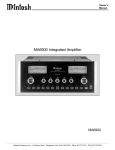
MC2000 Tube Power Amplifier New Millennium Edition 50th Anniversary 1949 - 1999 MC2000 OWNERS MANUAL A Brief History of McIntosh Frank H. McIntosh Gordon J. Gow 2 For Fifty Years 1999 is the 50th year of business for McIntosh Laboratory of Binghamton, New York. It all started when Frank H. McIntosh organized a small electronic engineering consulting firm in the Washington, DC area. One of the many goals his firm addressed was the need for a high quality audio power amplifier. No existing amplifier at that time could reproduce the entire audio range from 20Hz to 20,000Hz with low distortion. Mr. McIntosh had a dream. He wanted to create an audio power amplifier that would far surpass the limited performance capabilities of any power amplifier available in 1948. Mr. McIntosh assembled a small team of talented and dedicated people who shared his ideas, and formed the original McIntosh Engineering Laboratory. This beginning staff included Gordon J. Gow and from 20 cycles to 20,000 cycles with less than 1% distortion. Now it was possible to reproduce music with a new degree of sonic accuracy that had never before been possible. The success of the company was secure. Additional new models were added and the company expanded into new facilities in Binghamton, New York in 1951. At that time the company name was changed to the now familiar McIntosh Laboratory, Inc. Gordon Gow advanced to become ExecuThe Original McIntosh tive Vice Presi50W1 Power Amplifier dent of Sales and after Frank McIntosh retired, became Company McIntoshs First Amplifier After months of research, the President for the last twelve dream had become reality. The years of his life. Maurice L. original McIntosh Power Am- Painchaud became Vice Presiplifier, the 50W1, was created. dent of Operations and the This amplifier was the first that Company Controller, and was could truly be described as High appointed President after the Fidelity, with 50 watts output untimely death of Gordon Gow. Maurice L. Painchaud, both of whom would spend the rest of their productive lives working for the company that later became McIntosh Laboratory, Inc. Initially both Mr. Gow and Mr. Painchaud were directly involved in design engineering. Maurice L. Painchuad Sidney A. Corderman The MC2000 was Designed by Sidney A. Corderman Sidney with the famous McIntosh MC275 which he designed Sidney A. Corderman In 1951, Sidney A. Corderman joined the Company as Chief Engineer. He was directly involved with the designs of all the successful McIntosh products from that time on. His electronic genius is unparalleled in the industry, and the advanced performance of McIntosh products reflects his expertise. McIntosh audio electronics have become the international standard for superior performance. After 50 years, McIntosh Laboratory is still producing stereo equipment dedicated to the same basic philosophy of providing the finest possible reproduction of music. The management and financial assistance of the present company owner, Clarion of Japan, has made it possible for McIntosh to greatly expand and upgrade its design and manufacturing facilities in Binghamton, New York. The home product lineup includes many new and popular models for both Stereo and Home Theater applications. A McIntosh Automotive Audio product line has been added that has achieved a reputation for performance, quality and reliability similar to the home products. MC2000 Amplifier After his retirement, Sidney Corderman was called back as interim President for a short period and is currently a member of the Board of Directors. Most recently he came out of retirement again to design the McIntosh MC2000, a 50th Anniversary Edition vacuum tube Power Amplifier. Pictured at the right are the C22 Preamplifier, MR71 FM Tuner and the MCD7000 CD Player, just three of the many McIntosh products designed by Sidney Corderman. McIntosh C22 Preamplifier McIntosh MR71 FM Tuner McIntosh MCD7000 CD Player 3 Thank You Technical Assistance Table of Contents Thank you for your decision to own this McIntosh MC2000 Tube Power Amplifier. You now have The Best. The McIntosh dedication to Quality, is assurance that you will receive many years of musical enjoyment from this unit. Please take the time to read the information in this Owners Manual. We want you to be as familiar as possible with all the features and functions of your new McIntosh MC2000. This will ensure that you receive all the performance benefits this equipment can offer you, and that it will become a highly valued part of your home entertainment system. If at any time you have questions about your McIntosh product, contact your McIntosh dealer who is familiar with your McIntosh equipment and any other brands that may be part of your system. If you or your dealer wish additional help concerning a suspected problem, you can receive technical assistance for all McIntosh products at: A Brief History of McIntosh ................................... 2 The MC2000 was Designed by Sidney A. Corderman ............................................. 3 Thank You ............................................................... 4 Take a Moment ....................................................... 4 Introduction ............................................................ 4 Technical Assistance ............................................... 4 Customer Service .................................................... 4 Table of Contents .................................................... 4 Safety Instructions .................................................. 5 Performance Features ............................................. 6 Installation .............................................................. 7 Rear Panel Connections ........................................ 10 How to Connect .................................................... 11 Front Panel Controls and Displays ....................... 13 How to Operate and Set the Bias .......................... 14 Technical Description ........................................... 16 Performance Charts .............................................. 20 Specifications ....................................................... 22 Packing Instruction ............................................... 23 Please Take A Moment The production number, purchase date and McIntosh dealer name are important to you for possible insurance claim or future service. The spaces below have been provided for you to record that information: Production Number: Purchase Date: Dealer Name: Introduction The MC2000 was created by Sidney A. Corderman, McIntosh Co-Founder, to commemorate the 50th year of business for McIntosh Laboratory (1949-1999), and the Year 2000 Millennium. The McIntosh MC2000 includes the latest innovations in vacuum tube power amplifier technology based on 50 years of audio design expertise. Two entirely separate power amplifiers and power supplies on a single chassis provide 130 watts per channel that is sonically transparent and absolutely accurate. The McIntosh sound is The Sound of the Music Itself. 4 McIntosh Laboratory, Inc. 2 Chambers Street Binghamton, New York 13903 Phone: 607-723-3512 Fax: 607-723-3636 Customer Service If it is determined that your McIntosh product is in need of repair, you can return it to your dealer. You can also return it to the McIntosh Laboratory Service Department. For assistance on factory repair return procedure, contact the McIntosh Repair Department at: McIntosh Laboratory, Inc. 2 Chambers Street Binghamton, New York 13903 Phone: 607-723-3515 Fax: 607-723-1917 Copyright 1999 ã by McIntosh Laboratory, Inc. NOTE: For additional connection information, refer to the owners manual(s) for any component(s) connected to the MC2000 Tube Power Amplifier. Safety Instructions IMPORTANT SAFETY INSTRUCTIONS! PLEASE READ THEM BEFORE OPERATING THIS EQUIPMENT. WARNING SHOCK HAZARD DO NOT OPEN. The lightning flash with arrowhead, within an equilateral triangle, is intended to alert the user to the presence of uninsulated dangerous voltage within the products enclosure that may be of sufficient magnitude to constitute a risk of electric shock to persons. AVIS RISQUE DE CHOC NE PAS OUVRIR. The exclamation point within an equilateral triangle is intended to alert the user to the presence of important operating and maintenance (servicing) instructions in the literature accompanying the appliance. NO USER-SERVICEABLE PARTS INSIDE. REFER SERVICING TO QUALIFIED PERSONNEL To prevent the risk of electric shock, do not remove cover (or back). No user serviceable parts inside. Refer servicing to qualified personnel. General: 1. Read all the safety and operating instructions contained in this owners manual, before operating this equipment. 2. Retain this owners manual for future reference about safety and operating instructions. 3. Adhere to all warnings and operating instructions. 4. Follow all operating and use instructions. 5. Warning: To reduce risk of fire or electrical shock, do not expose this equipment to rain or moisture. This unit is capable of producing high sound pressure levels. Continued exposure to high sound pressure levels can cause permanent hearing impairment or loss. User caution is advised and ear protection is recommended when playing at high volumes. 6. Caution: to prevent electrical shock do not use this (polarized) plug with an extension cord, receptacle or other outlet unless the blades can be fully inserted to prevent blade exposure. Attention: pour pevenir les chocs elecriques pas utiliser cette fiche polarisee avec un prolongateur, une prise de courant ou un autre sortie de courant, sauf si les lames peuvent etre inserees afond ans en laisser aucune partie a decouvert. 7. For added protection for this product during a lightning storm, or when it is left unattended and unused for long periods of time, unplug it from the wall outlet. This will prevent damage to the product due to lightning or power line surges. 8. Do not use attachments not recommended in this owners manual as they may cause hazards. Installation: 9. Locate the equipment for proper ventilation. For example, the equipment should not be placed on a bed, sofa, rug, or similar surface that may block ventilation openings; or, placed in a built-in installation, such as a bookcase or cabinet, that may impede the flow of air through the ventilation openings. 10. Locate the equipment away from heat sources such as radiators, heat registers, stoves, or other appliance (including amplifiers) that produce heat. 11. Mount the equipment in a wall or cabinet only as described in this owners manual. 12. Do not use this equipment near water; for example, near a bathtub, washbowl, kitchen sink, laundry tub, in a wet basement or near a swimming pool, etc. 13. Do not place this product on an unstable cart, stand, tripod, bracket, or table. The equipment may fall, causing serious injury to a person, and serious damage to the product. Connection: 14. Connect this equipment only to the type of AC power source as marked on the unit. 15. Route AC power cords so that they are not likely to be walked on or pinched by items placed upon or against them, paying particular attention to cords at plugs, convenience receptacles, and the point where they exit from the instrument. 16. Do not defeat the inherent design features of the polarized plug. Non-polarized line cord adapters will defeat the safety provided by the polarized AC plug. If the plug should fail to fit, contact your electrician to replace your obsolete outlet. Do not defeat the safety purpose of the grounding-type plug. 17. Do not overload wall outlets, extension cords or integral convenience receptacles as this can result in a risk of fire or electric shock. 5 Safety Instructions cont, and Performance Features Care of Equipment: 18. Clean the instrument by using the supplied special fabric cloth. Unplug this equipment from the wall outlet and clean the front panel with a regular cloth moistened with a window cleaner. Do not apply liquid or aerosol cleaners directly on the equipment. 19. Do not permit objects of any kind to be pushed and/or fall into the equipment through enclosure openings. Never spill liquids into the equipment through enclosure openings. 20. Unplug the power cord from the AC power outlet when left unused for a long period of time. Repair of Equipment: 21. Unplug this equipment from the wall outlet and refer servicing to a qualified service personnel under the following conditions: A. The AC power cord or the plug has been damaged. B. Objects have fallen, or liquid has been spilled into the equipment. C. The equipment has been exposed to rain or water. D. The equipment does not operate normally by following the operating instructions contained within this owners manual. Adjust only those controls that are covered by the operating instructions, as an improper adjustment of other controls may result in damage and will often require extensive work by a qualified technician to restore the product to its normal operation. E. The equipment has been dropped or damaged in any way. F. The equipment exhibits a distinct change in 6 performance - this indicates a need for service. 22. Do not attempt to service beyond that described in the operating instructions. All other service should be referred to qualified service personnel. 23. When replacement parts are required, be sure the service technician has used replacement parts specified by McIntosh or have the same characteristics as the original part. Unauthorized substitutions may result in fire, electric shock, or other hazards. 24. Upon completion of any service or repairs to this product, ask the service technician to perform safety checks to determine that the product is in proper operating condition. Balanced connections guard against induced noise and allow long cable runs without compromising sound quality. · Illuminated Power Meters Two accurate, peak responding output meters continuously indicate the power delivered by each channel. A Peak Hold Meter Mode indicates the maximum power reached over a given time span. The meter illumination can be turned off so as to not detract from the listening environment, if desired. Performance Features · Gold Plated Connectors Gold Plated Input jacks provide trouble free connections. Gold Plated 200 ampere Output Binding posts accept spade lugs, banana plugs or speaker cable up to #8 AWG diameter. · Power Output The MC2000 is a Dual Mono design which consists of two entirely separate Mono, 130 watt vacuum tube power amplifiers, each with its own power supply. Output impedance connections are provided for 2, 4 and 8 ohm loudspeaker loads. · Ceramic Tube Sockets with Gold Contacts Ceramic tube sockets with gold plated contacts provide firm, reliable connections that are not affected by atmospheric contamination. Output tube sockets include Air-Pipe cooling at their bases. · · Patented Bifilar Wound Transformers and Output Circuit The power output sections utilize the famous McIntosh patented Unity Coupled Circuit with a Bifilar Wound Output Transformer for low distortion, extended frequency response and cool operating output tubes. · Balanced and Unbalanced Inputs Both Balanced and Unbalanced Inputs are included. High Technology Power Supplies All voltages are electronically regulated or filtered for stable operation. Twin regulated DC heater supplies are provided for the Input tubes. · Glass Front Panel and Gold Plated Chassis The famous McIntosh Illuminated Glass Front Panel and the Stainless Steel Chassis with Titanium Gold Super Mirror Finish ensures the pristine beauty of the MC2000 will be retained for many years. Installation Installation The installation of the MC2000 Tube Power Amplifier in your system consists of three main steps: 1. Unpacking the MC2000 along with accessories from their shipping cartons. 2. Installation of the vacuum tubes and the protective tube cover. 3. Finally, the physical placement of the MC2000 in your system. Note: Two pairs of white gloves have been provided to prevent fingerprinting of the MC2000 during handling. It is also recommended the gloves be used during the installation of the Vacuum Tubes into the MC2000. Unpacking the Amplifier and Accessories The MC2000 Amplifier and accessories have been packaged in specially designed shipping cartons, to MC2000 Amplifier protect them from potential shipping damage and allow for easy removal from the cartons. Please refer to the following steps. Caution: The MC2000 Amplifier weight is 135 pounds (61.2 kilograms). It requires two or more persons to safely handle when moving the amplifier. Unpacking the Amplifier: 1. Remove the shipping carton banding strap(s), if any. Note: If these banding straps are metal, use caution as the straps are under tension and may have sharp edges when cut. 2. Lift off the top of the outer shipping carton. 3. Lower the side flaps of the outer shipping carton. 4. Lift off the top of the inner shipping carton. 5. Lower the side flaps of the inner shipping carton. 6. Lift off the individual layers of foam packing material from the MC2000. Refer to figure 1. 7. Put on the pair of white gloves (this will prevent fingerprinting of the MC2000 during handling). 8. Remove the plastic shipping bag. Unpacking the Accessories: 1. Open the outer shipping carton. 2. Remove the inner carton from the outer shipping carton. 3. Open the inner carton. Refer to figure 2. 4. Remove the accessories from the inner carton. Tube Cover Plastic Bag Power Cord Screwdriver Adjustment tool Tube Cover fastening screws Foam Layers Tube Box Inner Carton Inner Carton Figure 1 Figure 2 7 Installation of Tubes and Cover Your MC2000 has gone through an extensive series of performance tests during the manufacturing process. The actual tubes that were used to test and confirm the performance of this amplifier are included in the McIntosh MC2000 Tube Set Box, refer to figure 3. Inside the tube set box is a plastic overlay that Note: White gloves have been provided to prevent fingerprinting of the Vacuum Tubes during their installation into the MC2000. Power Output Tubes: 1. Locate tube V4L (KT88 or 6550) in the Tube Set Box (Left side of the Box). 2. Locate the matching tube socket on the MC2000 Chassis (Left side of the Amplifier). Small Signal Tubes: 1. Locate tube V1L (12AX7A) in the Tube Set Box (left side of the box). Note: There are two different types of small tubes (12AX7A and 12AT7) used in each channel. The MC2000 will not function if they are inserted into the wrong socket. 2. Locate the matching tube socket on the MC2000 Chassis (left side of the amplifier). Plastic Overlay V4L (KT88/6550) V1L (12AX7A) Shipping Screws Location Left Channel Tubes Right Channel Tubes Figure 3 identifies each tube and its specific socket location in the amplifier. The MC2000 Chassis has nomenclature screened on it to specify both the circuit location and tube type for each channel, refer to figure 4. It is extremely important to insert the tubes in the correct location. Below is an example for installing one of the power output and small signal tubes into the MC2000 Tube Sockets for Left Channel: Caution: To prevent electrical shock make sure that the MC2000 AC POWER CORD IS NOT CONNECTED to the unit when inserting or removing tubes, as there are hazardous voltages present at the pins of the tube sockets. 8 Figure 4 3. Orient the tube so that the key on the base of the tube is aligned with the corresponding key on the tube socket. 4. Carefully insert the tube into the socket until the base of the tube is fully seated in the tube socket. 5. Repeat the above the steps for the remaining 7 Power Output Tubes, refer to figure 5. Figure 5 3. Orient the tube so that the area where no pins are located on the base of the tube is aligned with the corresponding area on the tube socket. 4. Carefully insert the tube into the socket until the base of the tube is fully seated in the tube socket. 5. Repeat the above steps for the remaining 5 Small Signal Tubes, refer to figure 5. Installation, cont After all the tubes have been inserted into the correct sockets, the tube cover must to be installed before operating the MC2000. Locate the tube cover and the two long fastening screws and perform the following steps: Installing the Tube Cover: 1. Orient the MC2000 so the Front Panel is facing you. Tube Cover Fastening Screw Locations Tube Cover Wide Side Opening Figure 6 2. Remove the two shipping screws from the MC2000 Chassis with the supplied screwdriver, refer to figure 5. 3. The Tube Cover has a wide opening along one side of its longer dimension. Orient this wide opening so that it is facing towards you. 4. Insert the supplied long screws into each top side of the tube cover so they extend below the bottom edge. 5. Carefully place the Tube Cover onto the MC2000 while at the same time aligning the screws with the openings on the MC2000 Chassis, refer to figure 6. 6. Using the supplied screwdriver secure the tube cover to the chassis, do not over tighten the screws. Location and ventilation Adequate ventilation extends the trouble free life of any electronic instrument. The suggested minimum space for mounting the MC2000 is 20 inches (50.8cm) in width, 22 inches (55.9cm) depth, and 17 inches (43.18cm) in height. Always allow air to flow through the ventilation holes on the botFigure 7 tom of the amplifier and a means for the warm air to escape at the top. If all the components are installed in a single cabinet, one or more quiet running ventilation fans can be a definite help in maintaining all the system components at their coolest possible operating temperatures. Refer to figure 7. Warm Air Cool Air 9 MC2000 Rear Panel Connections POWER CONTROL IN and OUT receives a turn-on signal and sends it to another McIntosh Component MODE SWITCH selects Balanced or Unbalanced Inputs for both the Left and Right Channels RIGHT CHANNEL BALANCED INPUT for audio cables from a Preamplifier or Control Center Audio Outputs LEFT BALANCED INPUT for audio cables from a Preamplifier or Control Center Audio Outputs RIGHT UNBALANCED INPUT for audio cables from a Preamplifier or Control Center Audio Outputs LEFT UNBALANCED INPUT for audio cables from a Preamplifier or Control Center Audio Outputs RIGHT OUTPUT connections for 2, 4 or 8 ohm loudspeakers 10 INPUT SWITCH selects the desired amplifier sensitivity setting for both the Left and Right Channels FUSE 2 HOLDER for the Right Channel, refer to information on the top rear panel of your MC2000 to determine the correct fuse size and rating Connect the MC2000 power cord to an active AC outlet. Refer to information on the back panel to determine the correct voltage FUSE 1 HOLDER for the Left Channel, refer to information on the top rear panel of your MC2000 to determine the correct fuse size and rating LEFT OUTPUT connections for 2, 4 or 8 ohm loudspeakers How to Connect the MC2000 How to Connect the MC2000 1. For Remote Power Control, connect a power control cable from the Control Center or Preamplifier Power Control Out to the MC2000 Power Control In. McIntosh C100 Controller Note: The Power Control Connecting Cable is available from the McIntosh Parts Department: Data and Power Control Cable Part No. 170202; six foot, shielded 2 conductor, with 1/8 inch stereo mini phone plugs on each end. 2. Connect the MC2000 power cord to an active AC outlet. Note: Make sure that the MC2000 Front Panel Power Control is in the OFF position. To AC Outlet 11 How to Connect the MC2000, cont 3. Connect cables from the balanced outputs of a McIntosh Preamplifier or Control Center to the MC2000 Balanced Inputs. Notes: 1. An optional hookup is to use unbalanced cables from a preamplifier or control center to the MC2000 unbalanced inputs. 2. The MC2000 may be connected in a Bridge Mono Mode for a total of 260 watts output, contact your dealer or McIntosh for details. 4. Connect the loudspeaker hookup cables to the output terminals, which will accept bare cable ends, spade lugs, or banana plugs. Attach cables to the terminals that match the impedance of your loudspeakers, being careful to observe the correct polarities. Output impedance connections of 2 ohms, 4 ohms and 8 ohms are provided. Notes: 1. If the impedance of your loudspeakers is different from the listed impedances, use the nearest lower impedance connection. 2. It is very important that loudspeaker cables of adequate size be used, so that there will be no power loss or heating. Cable size is specified in Gauge numbers or AWG, (American Wire Gauge). The smaller the Gauge, the larger the wire size: If your loudspeaker cables are 50 feet (38.1m) or less, use 14 (AWG) wire size or larger. If your loudspeaker cables are 100 feet (76.2m) or less, use 10 (AWG) wire size or larger. Right Speaker 12 123456789012 123456789012 123456789012 123456789012 123456789012 123456789012 123456789012 123456789012 123456789012 123456789012 123456789012 123456789012 123456789012 123456789012 123456789012 123456789012 123456789012 Spade lug or prepared wire connection: Insert the spade lug connector or prepared section of the cable end into the terminal side access hole, and tighten the terminal cap until the cable is firmly clamped into the terminal so the wires cannot slip out. Refer to figures 8, 9 & 10. How to prepare cable ends: A. Carefully remove sufficient insulation from the cable ends to just fit within the binding post with no exposed wire accessible. B. If the cable is stranded, carefully twist the strands together as tightly as possible. Refer to figures 11, 12 & 13. Banana plug connection: Insert the banana plug into the hole at the top of the terminal and tighten the top portion of the terminal post to secure the banana plug in place. Note: If desired, the twisted ends can be tinned with solder to keep the strands together, or attach spade lug and/or banana connector. Note: If the cables come without prepared ends, proceed to How to prepare cable ends. McIntosh C100 Preamplifier 1234567890123 1234567890123 1234567890123 1234567890123 1234567890123 1234567890123 1234567890123 1234567890123 1234567890123 1234567890123 1234567890123 1234567890123 1234567890123 1234567890123 1234567890123 1234567890123 1234567890123 Left Speaker MC2000 Front Panel Controls and Displays METER indicates the Right Channel Power Output, switchable to indicate bias readings of each pair of Right Channel Output Tubes METER indicates the Left Channel Power Output, switchable to indicate bias readings of each pair of Left Channel Output Tubes POWER Switch turns AC Power, ON/OFF, or ON/REMOTE modes METER Switch selects the display modes of the power output meters Remote On Indicator 13 How to Operate the MC2000 Power On To have the MC2000 automatically turn On or Off when a Control Center turns On or Off, rotate the POWER Switch to the REMOTE position. For manual operation, rotate the power switch to the ON or OFF position as desired. Note: There must be a power control connection between the MC2000 and the McIntosh Control Center, in order for the Remote Power Turn On to function. Mode Switch Use the MODE Switch to select either the Balanced or Unbalanced inputs. Refer to figure 14. Note: The MODE Switch is located on the top panel (rear) of the MC2000. Location of INPUT and MODE Switches Figure 14 14 How to Set the Bias Input Switch The INPUT Switch allows selection of two different input sensitivities. Refer to figure 14. 2.5V The recommended sensitivity when McIntosh Preamplifiers or Control Centers are being used. 1.2V An increased sensitivity for any signal source that is rated for less than 2.5V output. Note: The INPUT Switch is located on the top panel at the rear of the MC2000. Meter Selection Rotate the Meter Mode Switch to select the Meter Operation Mode desired. Lights Off Meter lights are turned off and the meters will indicate the power output. Watts The meters indicate the power output and respond to all the musical information being reproduced by the amplifier. They indicate to an accuracy of at least 95% of the power output of either amplifier channel with only a single cycle of a 2000Hz tone burst. Hold The meter pointer locks to the highest power peak in a sequence of peaks. The meter is electronically held to this power level until another higher power peak passes through the amplifier. The meter pointer will then rise to the newer higher indication. If no further power peaks are reached, the meter pointer will very slowly return to its rest position or lower power level. The decay rate is approximately 6dB per minute. The BIAS ADJustments were made during the final testing of the MC2000 at the factory. When you care to make BIAS ADJustments, please follow the steps as listed: Note: Bias adjustments are not critical, and are only necessary when the tubes have aged or been replaced. Caution: To prevent electrical shock make sure that the MC2000 AC POWER CORD IS NOT CONNECTED to the unit when inserting or removing tubes, as there are hazardous voltages present at the pins of the tube sockets. 1. Remove the BIAS ADJustment Protective Covers on each side of the MC2000. Refer to figure 15. Note: Figure 15 shows the location of the BIAS ADJustments for the Right Channel, which are located on the right side of the MC2000. The BIAS ADJustments for the Left Channel are located on the left side of the MC2000, in the same location. Location of BIAS ADJustments Figure 15 2. Switch Power On to the MC2000, and wait for about 30 minutes before making any adjustments. Note: When the tube(s) are replaced, set the corresponding bias control(s) to the fully counterclockwise position before turning on the How to Operate the MC2000 and Set the Bias MC2000. After the amplifier has been on for about 2 minutes make an initial adjustment (as outlined below). This should then be followed by a final adjustment after the MC2000 has been on for about 30 minutes. Momentary Push-buttons 3. Facing the Left Side of the MC2000 press and hold in the momentary push-button for V4+6 L, and at the same time carefully adjust the BIAS Potentiometer V4+6 L for a MC2000 Left Meter indication centered between .13 and 1.3. Refer to figures 16 and 18. Momentary Note: The tip of a pen, or other appropriate pointed tool, can be used to push in the momentary pushbutton. BIAS Potentionmeters Figure16 Left Side of the MC2000 4. In a similar manner, adjust BIAS Potentiometer V5+7 L for the same meter indication centered between .13 and 1.3. 5. Facing the Right Side of the MC2000 press and hold in the momentary push-button for V5+7 R, and at the same time carefully adjust the BIAS Potentiometer V5+7 R for a MC2000 Right Meter indication centered between .13 and 1.3. Refer to figures 17 and 18. Note: The tip of a pen, or other appropriate pointed tool, can be used to push in the momentary pushbutton. BIAS Potentionmeters Figure 17 Right Side of the MC2000 6. In a similar manner, adjust BIAS Potentiometer V4+6 R for the same meter indication centered between .13 and 1.3. Figure 18 15 Technical Description In the late 1940s Frank McIntosh and Gordon Gow invented and patented a new output circuit arrangement for audio power amplifiers, the McIntosh Unity Coupled Output Circuit. Refer to figure 19. This circuit has two McIntosh Unity Coupled Output Circuit very important features that differentiate it from other designs. First, the output tubes deliver their power from both their plates and their Figure 19 cathodes, not from their plates alone as in conventional circuits. Second, the Unity Coupled Output Transformer, having two bifilar primary windings (one for the plate and the other for the cathodes), has one half the turns ratio (equating to one fourth the impedance ratio) of conventional output transformers. The resulting benefits are much lower distortion produced in the output stage and improved transformer design giving very close coupling primary to secondary for flat frequency response and wide power bandwidth. MC2000 Application The MC2000 uses the Unity Coupled Output Circuit with KT-88 or 6550 output tubes in a push-pull parallel configuration. These tube types are selected because of their excellent power and voltage ratings plus the favorable experience McIntosh has had with 16 them in the MC275 and other amplifier models. The output tubes deliver signal to the output transformer through two primary windings, one for the plates and the other for the cathodes. These windings are wound bifilar, which means that both windings are wound together, two wires, at the same time. The secondary consists of five separate windings interspersed within the primary windings. These five windings are connected in parallel. Very tight coupling is obtained, which achieves wide bandwidth and flat frequency response. The transformer core is four and one half square inches of grain oriented silicon steel. This allows full power output down to 17 hertz. Refer to figure 20, MC2000 Block Diagram of the Amplifier Section. The output tubes operate with fixed bias, which is adjustable and metered as explained later. Because the output tubes are loaded in their cathodes, they require a large grid drive signal of approximately 170 volts for full output. This signal is provided by the 12AT7 driver stage. The plates of the driver are resistance-capacitance coupled to the output tubes. Plate loading for the driver is boot strapped to the plate winding of the output transformer. Boot strapping increases the effective plate load to the driver providing greater amplification than otherwise possible. A Darlington emitter follower stage is used at the grids of the output tubes to provide a relatively low impedance to eliminate possible bias runaway due to output tube grid current. Inside of the MC2000 Technical Description E>;C064 =51 D=10;0=243 10;0=243 !E!$E 8=?DC D=10;0=243 ;4E4; A4;0H A4;0H <DC4 3A8E4A 1D554A 0<? ;45C D=8CH >DC?DC 1D554A 0<? 0<? ' 608= 0<? >DC?DC # 180B 8=?DCB CA0=B 10;0=243 2>=CA>; 5>A<4A - D=8CH ! W W W ;45C >DC?DC 2>< 8=E4AC8=6 ?70B4 3A8E4A 1D554A 0<? 8=E4AC4A >DC?DC 1D554A 0<? 0<? 32 0<? ;<4C4A ;>6 32 A42C8584A 0<? Block Diagram of the Amplifier Section 0<? 7>;3 28A2D8C 10;0=243 8=?DC <4C4A D=10;0=243 ;4E4; 7>;3 <>34BF8C27 BF8C27 BF8C27 7>;3 28A2D8C ;>6 32 A42C8584A 0<? 0<? A<4C4A 32 0<? - ?70B4 D=8CH 8=E4AC4A 3A8E4A 1D554A 0<? >DC?DC 1D554A 0<? 8=E4AC8=6 ' 0<? >DC?DC 10;0=243 # 180B CA0=B A867C 2>=CA>; 5>A<4A 8=?DCB D=8CH A867C >DC?DC 608= 2>< 0<? 10;0=243 !E!$E 8=?DC D=10;0=243 ;4E4; <DC4 3A8E4A 1D554A 0<? D=10;0=243 ! W W W A4;0H >DC?DC 1D554A 0<? 0<? A4;0H E>;C064 =51 Figure 20 17 The driver stage is fed by the 12AX7A input/ phase inverter stage. A resistance-capacitance step network couples this stage to the driver. This arrangement controls low frequency phase shift. The phase inverter uses no coupling capacitors so no low frequency phase shift is introduced. Emitter follower stages are used at the plates of the 12AX7A. This isolates the capacity loading of the driver input and increases the bandwidth of the input/inverter stage. Proper Application of Feedback Global negative feedback is taken from the output transformer secondary to the cathode of the input stage. There is a school of thought that global feedback is not desirable. It is a scientific fact that many benefits result from properly applied global feedback. Among them are a decrease in distortion, a decrease in noise level, flatter frequency response, a decrease in rise time, and an increase in output damping factor. If not done properly amplifier instability can result and this has been considered. One misconception is that the feedback signal is delayed from the amplifier input signal and therefore introduces time distortion. This concept is wrong when a properly designed amplifier circuit is considered. The phase delay introduced by the entire MC2000 circuit is less than 2 microseconds, which is certainly of no acoustic significance. MC2000 in Balanced Mode When the balanced amplifier input is selected, a second 12AX7A receives the balanced signal. One section of the tube is a cathode follower which passes the positive phase signal. The other section inverts the negative phase signal. The two outputs are combined and feed to the input/phase inverter stage de18 scribed above. Common mode rejection is greater than 60 dB at mid frequencies. Slide switches at the rear of the chassis allow selecting balanced or unbalanced inputs and to select input signal sensitivity of 1.2 volts or 2.5 volts for full power output. At the 1.2 volt setting 1 volt of input signal will produce 100 watts output. The slide switches operate reed relays located at the front of the chassis adjacent to the input circuits. Refer to figure 21, MC2000 Block Diagram of the Power Supply. Power Transformers Each power transformer includes two tapped primary windings and three secondary windings. Refer to figure 21. The primary can be connected for 100, 120, or 230 volts by plug connections within the chassis. A thermistor in series with the power line input to the transformer primary cushions the inrush surge current. The high voltage secondary winding feeds bridge rectifiers followed by capacitor input filters. A Power MOS FET is used in place of a filter choke, followed by a large output filter capacitor. The voltage drop across the MOS FET is constant at all output levels resulting in excellent power supply filtering. A medium voltage secondary winding feeds the negative bias voltage supply. A low voltage secondary winding feeds the heaters of the output tubes, driver tube and panel lamps. This same winding also feeds regulated DC power supplies for the heaters of the 12AX7A input stages and the meter circuits. Power Meters The power output of each amplifier channel is monitored by separate meters. The amplifier output signal is fed to a log converter amplifier, then to a peak de- tector, a pulse stretcher, then to a driver amplifier and the meter. The meter displays the output power being delivered by that channel and is calibrated in watts. The Meter Switch on the front panel allows the meter to be switched from the normal output mode to a Peak Hold mode which allows the meter to temporarily stay at the highest power reading during a given time, with a gradual decay if power levels drop. The meter switch also can turn off the meter lamps should that be desired. The meter also serves as an indicator for setting the bias for the output tubes. At the side of the chassis there are bias adjust controls and small push switches. When a switch is pressed the amplifier is muted and the meter is connected to measure the current flow in the output tubes. The adjustment is not critical and should only be required when output tubes are replaced. Power Control The Power Switch has three positions, OFF, REMOTE, and ON. OFF and ON allow for manual operation. REMOTE allows power to be controlled by a command coming from a McIntosh Control Center or Preamplifier. A red LED on the front panel lights to indicate that the REMOTE position has been selected, and the amplifier is in the standby mode. Technical Description, cont Block Diagram of the Power Supply Section !E02 ;45C !E 32 8=ADB7 8=?DC 2DAA4=C E>;C064 !E 32 <08=$E 32BD??;H $0=3 $0=3 ?>F4A "E32 BD??;H ?>F4A BD??;H "E32 ?>F4A 5DB4 CA0=B5>A<4A ;8<8C4A B4;42C>A !E02 !!"E02 $%7i ?>F4A A4;0H !E 32 8=ADB7 !E 32 <08=$E 32BD??;H A867C 8=?DC ?>F4A 5DB4 2DAA4=C E>;C064 ;8<8C4A B4;42C>A CA0=B5>A<4A 8= BC0=31H 2>=CA>; ?>F4A ?>F4A CA0=B5>A<4A $EBD??;H BF8C27 2>=CA>; A4<>C4 5DB4 902:B >DC A4<>C4 ;0<? Figure 21 19 Total Harmonic Distortion vs. Frequency @ 8 Ohms 0.5 0.4 THD % 0.3 0.2 0.1 20 50 100 200 500 1k 2k 5k 10k 20k Hz (Hertz) Frequency Response @ 1 Watt +0 -5 dB (Decibel) -10 -15 -20 -25 10 20 50 100 200 500 1k 2k 5k 10k 20k 50k 100k Hz (Hertz) dB (Decibel) Signal to Noise Ratio FFT Spectrum Analysis ref. full power +0 -100 20 50 100 200 500 1k 2k 5k Hz (Hertz) Note: These Performance Charts are examples of typical performance of the MC2000. 20 10k 20k Performance Charts Total Harmonic Distortion vs. Power Output @ 20Hz 4 3 THD % 2 1 -0 300m 500m 1 2 5 10 20 50 100 200 Power in Watts Total Harmonic Distortion vs. Power Output @ 1kHz 4 3 THD % 2 1 -0 300m 500m 1 2 5 10 20 50 100 200 100 200 Power in Watts Total Harmonic Distortion vs. Power Output @ 20kHz 4 3 THD % 2 1 -0 300m 500m 1 2 5 10 Power in Watts 20 50 Note: These Performance Charts are examples of typical performance of the MC2000. 21 Specifications Specifications Power Output 130 watts into 8, 4 or 2 ohm loads is the minimum sine wave continuous average power output per channel from 20Hz to 20,000Hz with both channels operating. Total Harmonic Distortion 0.5% maximum harmonic distortion at any power level from 250 milliwatts to rated power per channel from 20Hz to 20,000Hz with both channels operating. Intermodulation Distortion 0.5% maximum intermodulation distortion if instantaneous peak power output does not exceed twice the output rating per channel with both channels operating, for any combination of frequencies from 20Hz to 20,000Hz. Rated Power Band 20Hz to 20,000Hz Frequency Response (at 1 watt) +0, -0.25dB from 20Hz to 20,000Hz +0, -3dB from 10Hz to 100,000Hz Hum and Noise (A-Weighted) 100dB below rated output Damping Factor Greater than 18 Output Load Impedance 2, 4 or 8 ohms 22 Input Impedance 20K Ohms Unbalanced (RCA Phono Jacks) 40K Ohms Balanced (XLR Connectors) Input Sensitivity (Switch Selectable) 2.5 volts for rated output 1.2 volts for rated output (1 volt for 100 watts output) Tubes Compliment 8 KT88 or 6550 Output Tubes 4 12AX7A Input Tubes 2 12AT7 Driver Tubes Power Requirement 100 Volts, 50/60Hz at 5.8 Amps 120 Volts, 50/60Hz at 4.8 Amps 230 Volts, 50/60Hz at 2.5 Amps Note: Refer to the rear panel of the MC2000 for the correct voltage. Dimensions 17-3/4 inches (45.1cm) wide by 11 inches (27.9cm) high. Depth behind front panel is 18-3/4 inches (47.6 cm). Handle clearance required in front of the mounting panel is 1-5/8 inches (4.1 cm). Finish Stainless Steel Chassis with Titanium Gold Super Mirror Finish, Black Transformer Enclosures, Black Base, Glass Front Panel with gold plated Handles and Knobs Weight Amplifier - 135 pounds (61.2 kg) net, 144 pounds (65.3 kg) in shipping carton Accessories - 18 pounds (8.2 kg) in shipping carton Packing Instructions Packing Instructions In the event it is necessary to repack the MC2000 Amplifier for shipment, the equipment must be packed exactly as shown below. It is very important that the four metal feet are attached to the bottom of the equipment. This will ensure the proper location of the MC2000 on the bottom foam pad. The Vacuum Tubes and Tube Cover must be removed from the MC2000 Amplifier and packaged separately. Failure to do this will result in shipping damage. Use the original shipping carton and interior parts only if they are all in good serviceable condition. If a shipping carton or any of the interior part(s) are needed, please call or write Customer Service Department of McIntosh Laboratory. Please see the Part List for the correct part numbers. Power Amplifier Carton: Quantity Part Number 1 033096 1 034097 3 034098 1 034099 1 034100 1 034101 4 018626 Accessory Carton: Quantity Part Number 1 034109 1 1 1 034108 034111 034112 Description Poly bag Bottom foam pad Foam ring Top foam pad Carton Top Carton Bottom Metal foot Description Tube carton (gold) with foam pads Inside carton (white) Outside carton (kraft) Foam pad set Note: Refer to page 7 in this Ownerss Manual for a view of the Accessory Carton. 23 McINTOSH LABORATORY, INC. 2 CHAMBERS STREET, BINGHAMTON, NEW YORK 13903-2699 The continuous improvement of its products is the policy of McIntosh Laboratory Incorporated who reserve the right to improve design without notice. Printed in the U.S.A. Part No. 040662