1
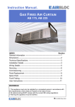
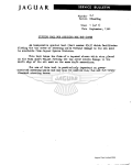
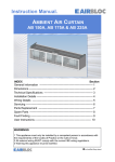
Instruction Manual. ACT-1 COMMERCIAL & RETAIL RECESSED CEILING TILE HEATER & SURFACE MOUNTED STOCKROOM HEATER INSTALLATION AND OPERATING MANUAL INDEX Section General Information ----------------------------------------------------------- 1 Dimensional Data -------------------------------------------------------------- 2 Technical Specification ------------------------------------------------------- 3 Electrical Connections -------------------------------------------------------- 4 Installation Details ------------------------------------------------------------- 5 User Instructions --------------------------------------------------------------- 6 Maintenance --------------------------------------------------------------------- 7 Spares & Servicing ------------------------------------------------------------ 8 Replacement Parts ------------------------------------------------------------- 9 WARNINGS 1 This appliance must only be installed by a competent person in accordance with the requirements of the Codes of Practice or the rules in force. 2 All external wiring MUST comply with the current IEE wiring regulations. 3 Warning this appliance must be earthed. 1. General Information. 1.1 Introduction This instruction manual describes the Airbloc ACT -1 range of Recessed Ceiling Tiles and Surface Mounted Stockroom Heaters from 3-6kW. To ensure continued and safe operation it is recommended that the appliance is serviced annually. The Airbloc ACT-1 range are electric heater that directs a down-flow of warm air from overhead, delivering immediate heat where required and rapidly creating a comfortable environment for staff and customers. The manufacturer, offers a maintenance service. Details are available on request. The Airbloc ACT-1 recessed ceiling heater is designed for discreet positioning in a suspended 600mm ceiling. It is supplied complete with a remote mounting control box. This unit is suitable for connection to 230/240V 50Hz supplies. Maximum cable inlet size is 4mm². 1.3 Electrical The appliance shall be connected to the supply via an appropriate switched fused double pole isolator having a contact separation of greater than 3mm. The connection to be made between the heater and the remote control box are detailed in section 4 - Electrical connections. BMS control, time switches, room thermostats and door interlocks can be installed at the discretion and responsibility of the installer. The Airbloc ACT-1 surface mounted ceiling heater is designed for suspension from a ceiling using threaded bar. It is supplied with stud bar mounting kit, painted enclosure and remote mounting control box. For safety reasons, a sound earth connection must be made to the unit before it is put into use. The unit should be wired in accordance with IEE regulations for Electrical Equipment of Buildings. Warning For safety reasons a good earth connection must ALWAYS be made to the heater and control box. The ACT-1 is supplied with a remote control box which houses 3 rocker switches. These switches give ambient airflow plus two heat switching options. 1.2 General All installations must be in accordance with the regulations in force in the country of use. These instructions must be handed to the user on completion of the installation. Installers and service engineers must be able to demonstrate competence and be suitably qualified in accordance with the regulations in force in the country of use. For further details please refer to section 6 - User instructions in this manual. 1.4 Location All units should be installed horizontally. WARNING: It is recommended that the recessed ceiling heater is installed within the ceiling void or roof space and the surface mount ceiling heater be suspended from a solid fixing via four 10mm drop rods. THIS HEATER SHOULD NOT BE INSTALLED WHERE THERE IS A CORROSIVE ATMOSPHERE. Care must be taken to allow complete free air movement into the inlet grilles of the unit to ensure the correct working operation of the heater. If the ACT03-1/04-1 heaters are mounted close to the wall or corner, the discharge opening should face the wall. The minimum distance of 0.8m or 1.2m for the ACT06-1. 1.5 Clearance distances It is recommended that a minimum clearance of 50mm is allowed around the case and 30mm above the heater. The clearance allows for cable entry and prevents combustible surfaces over-heating. Minimum mounting height (floor to grille) is: 2.2m - ACT03-1/ACT04-1 2.5m - ACT06-1. The recommended mounting height is: 2.5m - ACT03-1/ACT04-1 3.0m - ACT06-1. 1.6 Standards Units conform to the European electrical standard BS EN 60335-2-30 All must be wired in accordance with I.E.E regulations for the Electrical Equipment of Buildings. 1.7 Health and Safety Sole liability rests with the installer to ensure that all site safety procedures are adhered to during installation. Sole liability rests with the installer to ensure that protective safety wear such as hand, eye, ear and head protection is used during installation of the product. Do not rest anything especially ladders against the product. 2. Dimensional data. 309 63 Minimum Ceiling Void Height 175 210 Figure 1. ACT03-1/04-1 Recessed Ceiling Tile. 12 Foam Foam Diffuser 800 min 2200 min 595 x 595 floor 63 463 Figure 2. ACT06-1 Recessed Ceiling Tile. Foam Diffuser wall 595 x 595 2500 min 1200 min floor Figure 3. ACT-1 Surface Mounted Stockroom Heater. Foam 12 175 210 Minimum Ceiling Void Height wall 3. Technical Specification. ACT03-1 ACT04-1 ACT06-1 General Data Recommended height M 2.5 3.0 Min/max height M 2.2-3.0 2.5-3.5 Heat medium Maximum heat capacity Electric heated kW 3.0 4.5 Heat setting Heat setting 3 kW 1.0/2.0/3.0 1.5/3.0/4.5 Fan type Fan dia 2.0/4.0/6.0 Crossflow mm 60 Fan settings 1 Air outlet Fixed vent Switching type Weight Recessed / Surface Mounted 6.0 Remote switchbox kg 7 / 10 10 / 16 Electrical Data Maximum heat capacity kW 3.0 4.5 Supply voltage Total load 230V 1ph 50Hz amps Cable size External fuse size amps 6.0 13 20 2 x 2.5mm² + E amps Switch box wiring 16 27 2 x 4.0mm² + E 25 2 x 2.5mm² + E 32 2 x 4.0mm² + E Mains terminal block position Inside cover Control terminal block position Inside cover Air Data Fan setting Airflow Noise level 1 l/s 50 dBA 44 60 120 52 Dims Data Length mm nom 600 Depth mm nom 600 Total Height (incl terminal box) mm 175 (187 Surface Mounted) 4. Electrical Connections. These units are suitable for connection to 230/240V 50Hz supplies. Maximum cable inlet size is 4mm². The appliance shall be connected to the supply via an appropriate switched fused double pole isolator having a contact separation of greater than 3mm. The ACT-1 is supplied with a remote control box which houses 3 rocker switches. The mains supply can be fed either directly to the heater or the remote control box as per the following diagrams. For thermostatic control a room thermostat of appropriate switch rating maybe connected to the circuit. The thermostat should be wired between the isolator switch and the heater remote switch. For ACT04-1, ACT06-1 models or to control multiple ACT03-1 models by a thermostat, a contactor or a relay in conjunction with the thermostat should be used. F H1 H2 N E - Fan Heat 1 Heat 2 Neutral Earth If the heaters are to be controlled by means other than the remote switch supplied, eg BMS, than the heat output can be selected by connecting appropriate terminals shown in the table below. Figure 4. ACT-1 Terminal connections Note terminal ‘F’ must always be connected Unit / Wire terminals H1 + F + N H2 + F + N H1 + H2 + F + N ACT03-1 1.0kW 2.0kW 3.0kW ACT04-1 1.5kW 3.0kW 4.5kW ACT06-1 2.0kW 4.0kW 6.0kW * OUT L TC N Thermal Cut-out F IN OUT L M2 H2 H1 M Installer Terminals IN M1 OUT L N N 2kW L 1kW IN Heating Elements 230V 1Ph N L E fig 5. ACT03-1 electrical diagram, mains supply via remote switch H1 H2 * N Switchbox (reverse shown) Heater schematic * OUT L N OUT L H2 H1 Installer Terminals IN M2 M M1 OUT L * N Switchbox (reverse shown) denotes 30A, one way connector block Thermal TC Cut-outs F IN * TC Heater schematic N N 3kW L 1.5kW IN Heating Elements 230V 1Ph N L L1 E fig 6. ACT04-1 electrical diagram, mains supply via remote switch H1 H2 * F IN M2 H2 OUT L H1 M Installer Terminals IN M1 OUT L TC N N Thermal Cut-out M2 M M1 H1 H2 N N 2kW Thermal Cut-out 1kW L TC N Heating Elements OUT 2kW L 1kW IN Heating Elements 230V 1Ph N L L1 E fig 7. ACT06-1 electrical diagram, mains supply via remote switch H1 H2 N * Switchbox (reverse shown) Heater schematic F M2 H2 OUT L H1 M Installer Terminals IN Thermal Cut-out TC N M1 OUT L Switchbox (reverse shown) N N 2kW IN L 1kW L OUT * Heating Elements IN L 230V 1Ph N L E fig 8. ACT03-1 electrical diagram, mains supply direct to heater H1 H2 Heater schematic L N OUT L H2 H1 M2 M M1 OUT L Switchbox (reverse shown) * Thermal TC Cut-outs F Installer Terminals IN TC denotes 30A, one way connector block Heater schematic N N 3kW IN L OUT * 1.5kW IN L 230V 1Ph N L E fig 9. ACT04-1 electrical diagram, mains supply direct to heater H1 H2 fig 10. ACT06-1 electrical diagram, mains supply direct to heater H2 OUT L H1 OUT L M2 M M1 N TC N Thermal Cut-out M2 M M1 H1 H2 N N 2kW Thermal Cut-out F Installer Terminals IN TC 1kW L N Heating Elements * 2kW L OUT 1kW IN L Heating Elements IN 230V 1Ph N L E Heater schematic H1 H2 Switchbox (reverse shown) * denotes 30A, one way connector block Important: Two independent live feeds must be used on ACT04-1 and ACT06-1 heaters as shown in the wiring diagrams. 5. Installation Details. 5.1 ACT-1 Recessed unit The Airbloc ACT-1 recessed ceiling heater are designed to fit in place of a standard 600mm ceiling panel. It is essential that the ceiling frame is adequately supported to support the weight of the ACT-1 ceiling heater, or that the unit is individually supported. There is a provision on the unit for chain or wire support or mounting. The weight of the ACT03/04-1 is 7kg The weight of the ACT06-1 is 10kg It is the sole responsibility of the installer to ensure that the points of attachment to the building are Figure 11. ACT03-1/ACT04-1 Air discharge sound. Care must be taken to allow complete free air movement into the inlet grilles of the unit to ensure the correct working operation of the heater. Carefully unpack the unit and control box. The unit is supplied with a length of self-adhesive foam strip. This can be cut into lengths and is to be laid on the 4 sides of the ceiling frame. This will ensure that the unit assembly is free from vibration. The discharge grille and diffuser assembly can now be fitted into the ceiling frame. Ensure the air outlet is nearest the wall or corner of the room. Figure 12. ACT06-1 Air discharge 4 x M6 Mounting supports 4 x M6 Threaded inserts Top or side cable entry Figure 13. Mounting and installation views 5.2 ACT-1 Surface Mounted unit The Airbloc ACT-1 surface mounted ceiling heater is designed for suspension from a ceiling using threaded bar. The weight of the ACT03/04-1 is 12kg The weight of the ACT06-1 is 15kg It is the sole responsibility of the installer to ensure that the points of attachment to the building are sound. Care must be taken to allow complete free air movement into the inlet grilles of the unit to ensure the correct working operation of the heater. Carefully unpack the unit and control box. The unit is supplied with a length of self-adhesive foam strip. This can be cut into lengths and is to be laid on the 4 sides of the bottom of the heating casing. This will ensure that the unit assembly is free from vibration. A pair of machine screws hold each shroud half together at each joint. A machine screw secures each shroud half to each appliance beam. Figure 14. ACT03-1/ACT04-1 Air discharge Remove these machine screws and slide each shroud half off the appliance base panel. Note: The base panel fits inside the shroud halves. The diffuser is already clipped into and under the base panel and need not be removed. With the shroud removed the two appliance beams reveal the holes/slots shown and dimensioned below. It is required that two Ø10mm hanging rods (stud bars) support each appliance beam. The rods pass through and into each appliance beam. Support washers together with nuts locate and lock the appliance beams after adjustment to level the appliance. Replace Shroud Halves. Slide shrouds beneath and around base panel. Secure each shroud half to each appliance beam with machine screws. Screw shroud halves together at each joint. Ensure the air outlet is nearest the wall or corner of the room. Figure 15. ACT06-1 Air discharge Figure 16. Mounting and installation views Surface Mount 6. User Instructions. 6.1 Control The remote control box houses 2 switches, a double pole and a single pole, and gives the following functions: Switch ’FAN’ on = Off/Fan Only Switch ’I’ on = ⅓ Heat Switch ’II’ on = ⅔ Heat When both the centre switch and the right-hand switch are depressed the full heat output is available. ACT03-1 = 3.0kW, ACT04-1 = 4.5kW, ACT06-1 = 6.0kW 6.2 Protection The unit is protected in the event of fan failure, or an obstruction of the free air flow, by a thermal PTC Self Hold Cut Out. Having tripped the PTC Cut Out remains open, effectively switching off the heating elements, as long as mains power is available inside the appliance. Figure 17. Remote Control Box To switch on the appliance and operate the blower in Ambient mode, depress the left-hand switch (marked “FAN”). When the centre switch only (marked ‘I’) is depressed the heat output is ⅓ of full heat. ACT03-1 = 1.0kW, ACT04-1 = 1.5kW, ACT06-1 = 2.0kW. When the right hand switch only (marked ‘II’) is depressed the heat output is ⅔ of full heat. ACT03-1 = 2.0kW, ACT04-1 = 3.0kW, ACT06-1 = 4.0kW. The PTC Cut Out will only reset when the appliance is switched OFF and allowed to cool for at least 20 minutes. 6.3 To reset the PTC Self Hold Cut Out a) b) The cut-out is reset by switching OFF mains power to the appliance. Allow the appliance to cool for 20 minutes. Re-start, switch ON the appliance. If the Cut-out trips again, a qualified electrician should be consulted. 7. Maintenance ALWAYS ENSURE THAT THE MAIN EXTERNAL ELECTRICITY SUPPLY IS SWITCHED OFF BEFORE COMENCING ANY MAINTENANCE ON THIS HEATER. A single drop of light oil should be applied to the motor bearing from time to time. To obtain the best results from the heater, it is essential to avoid the accumulation of dust and dirt within the unit on the air inlet and discharge grilles. Other faults in relation to the element, motor and wiring should be identified using conventional fault finding techniques. For this reason regular cleaning is necessary, paying particular attention to the removal of dirt build up on the rotor blades. In the event that electrical components are replaced, please ensure that electrical safety checks in accordance with the regulations in force in the country of use are undertaken. All heaters are fitted with motor thermal protection. Cleaning of the fan is best carried out with a soft brush. 8. Spares & Servicing It is essential when ordering spares or replacement parts to state the model number and the serial number on the rating label adhered to the rear of the unit. The heater should be serviced annually. Airbloc offer a service facility, call 01384 489700. Any repair or alteration carried out to this product without the prior authority from AmbiRad will invalidate warranty. Refer to Air Curtain Installation and Operating Instruction manual for details. Ensure electrical power is isolated from the product. Servicing shall be undertaken by a competent person. 9. Replacement Parts ALWAYS ENSURE THAT THE MAIN EXTERNAL ELECTRICITY SUPPLY IS SWITCHED OFF BEFORE COMMENCING ANY WORK ON THIS HEATER. Fit replacement unit and re-assemble in the reverse order. 9.1 TO REPLACE A FAN/HEATER ASSEMBLY 9.2 TO REPLACE A SWITCH IN THE CONTROL BOX Switch off the mains supply. Switch off the mains supply. Split and remove shroud (Surface Mount only) Remove the switch box cover. Remove the grille. Disconnect the wiring to the switch. Disconnect the internal wiring from the blower Remove the appropriate fixing screw(s) and push out the switch. Remove the four screws fixing the fan heater assembly to the back case Fit the replacement switch, reconnect the wiring and replace the cover. The fan heater assembly can now be eased forward and removed from the heater case WARNING: THIS HEATER SHOULD NOT BE INSTALLED WHERE THERE IS A CORROSIVE ATMOSPHERE. Document reference number GB/AIR/072/0213