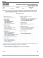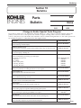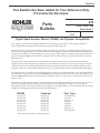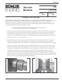
1
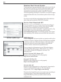
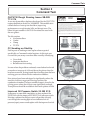
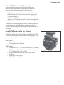
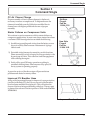
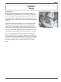
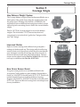
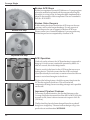
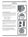
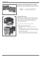
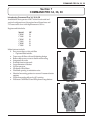
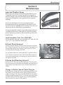
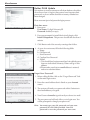
EFI
Table of Contents
Section 1 – EFI
Page No.
Installation Instructions TT-5109 .................................................................................................................. 5
New Malfunction Indicator Light ................................................................................................................... 5
New Primary High-Flow Fuel Filter .............................................................................................................. 5
Stainless Steel Ground Eyelets ................................................................................................................... 6
Service Pack Download SP1 ...................................................................................................................... 6
USB Adapters .............................................................................................................................................. 6
New Jump Start Hang Tag TT-5177 ............................................................................................................. 7
LH775 Overheating - Walker .................................................................................................................... 7-9
Section 2 – Command Twin
CH/CV750 Rough Running Issues SB-280/TT-5176.................................................................................. 11
CV Smoking on Start-Up ............................................................................................................................ 11
Improved Oil Pressure Switch 25 099 27-S ............................................................................................... 11
Improved Breather Hoses ......................................................................................................................... 12
DSAI Ignition System ............................................................................................................................ 12-13
Oil Coolers Replaced with High-Flow Fan................................................................................................. 13
Introducing Aluminized Muffler & Heat Shield ............................................................................................ 13
Connecting Rod Design Changes ............................................................................................................. 14
Miller Electric/Hobart R&R Procedure ....................................................................................................... 14
Kohler/Miller Dealer Match Program .......................................................................................................... 15
New CH750 Low-Profile Air Cleaner .......................................................................................................... 15
CV Oil Pan Gaskets .................................................................................................................................. 16
Section 3 – Command Single
CV Air Cleaner Change ............................................................................................................................. 17
Starter Failures on Compressor Units ....................................................................................................... 17
Improved CV Breather Hose ..................................................................................................................... 17
Section 4 – Aegis
Oil Dilution ................................................................................................................................................. 19
Section 5 – Courage Single
New Balance Weight System ...................................................................................................................
Improved Starter ........................................................................................................................................
New Grass Screen Guard .........................................................................................................................
Broken ACR Stops ....................................................................................................................................
Broken Valve Keepers ...............................................................................................................................
ACR Operation ..........................................................................................................................................
Improved Flywheel Fastener .....................................................................................................................
21
21
21
22
22
22
22
Section 6 – Courage Twin
Improved Rocker Adjustment ....................................................................................................................
New Muffler/Manifold Kit ............................................................................................................................
Smoking - Hillside Operation or Under Load .............................................................................................
New Fixed Guard/Housing Assembly ........................................................................................................
Teardown and Reassembly CDs & DVDs ................................................................................................
Courage PRO Twin ...................................................................................................................................
23
23
23
23
24
24
3
EFI
Section 7 – COMMAND PRO 34, 36, 38
Introducing COMMAND PRO 34, 36, 38 ................................................................................................... 25
Section 8 – Miscellaneous
Improved Breather Hoses ......................................................................................................................... 27
Low-Permeation Fuel Line, Bulk Roll ........................................................................................................ 27
Exhaust Studs Removed ........................................................................................................................... 27
K-Series Anti-Dieseling Solenoid ............................................................................................................... 27
Change in Kohler Special Tools Program .................................................................................................. 27
Kohler PLUS Update ................................................................................................................................. 28
Factory School Dates .......................................................................................................................... 29-30
Section 9 – Warranty/Re-Sign
New Warranty System for 2007 ................................................................................................................ 31
Carburetor Replacement Evaluation Form ........................................................................................... 31-32
Section 10 – Bulletins
Parts Bulletin 228 - Change in Kohler Special Tools Program .............................................................. 33-34
Parts Bulletin 233 - DSAM and Flywheel Compatibility (for reference only - no revisions) ........................ 35
Parts Bulletin 244 - Cylinder Head Service Kits for Command Twin Engines ........................................... 36
Service Bulletin 240 - Damaged Main Bearings ................................................................................... 37-38
Service Bulletin 276 - Carburetor Replacement Policy ........................................................................ 39-40
Service Bulletin 279 - Cracking/Deteriorating Molded Style Breather Hoses ............................................. 41
Service Bulletin 280 - CH/CV750 Momentary Sputtering, Interrupted Operation on Varying Terrain .......... 42
Section 11 – Service Program Test
Directions .................................................................................................................................................. 43
Service Program Test Questions ......................................................................................................... 44-50
Answer Sheet ............................................................................................................................................ 51
4
EFI
Section 1
EFI
Installation Instructions TT-5109
When repowering or installing a Basic EFI engine on new
equipment, please use TT-5109. This installation guideline has
been developed for both air and liquid-cooled EFI engines.
Helpful tips include:
• Proper mounting of components
ECU
Relay
Fuse
MIL
• Color code wiring details
• Fuel system layout information
• Battery cable size guideline
New Malfunction Indicator Light
In 2006, the Malfunction Indicator Light (MIL) was added to
the component list included with each Basic EFI engine. For
engines built before that time, or as a replacement, the
incandescent MIL is now listed in the Accessories Catalog
under Part No. 25 352 19-S.
New Primary High-Flow Fuel Filter
The CH745-0010 and CV745-0007 are Basic EFI engines.
Installation Instruction (TT-5109) requires the use of a 75-150
micron fuel filter with fittings/barbs for 5/16 in. I.D. fuel line. A
new 80 micron filter is now available from Kohler under Part
No. 24 050 12-S.
Malfunction Indicator Light
New Primary High-Flow Fuel Filter
5
EFI
Stainless Steel Ground Eyelets
There have been reports of stainless steel eyelets found in both
the 24 452 01-S and 24 755 134-S kit with recent date codes.
The correct eyelets should be tin-plated copper and can be
identified by scratching the surface with a file. The silvercolored tin plating can easily be scratched to reveal the copper
material underneath. Also, the stainless eyelets will not accept
solder.
If you have received these mispackaged parts, file a defective
parts claim and reorder the 24 452 01-S terminal.
Service Pack Download SP1
The latest version of the EFI Diagnostic Software package is
version 2.09 SP1. If you have version 2.09 without the SP1,
you will need to install this service pack for proper
communication with the older MA 1.7 (metal case) ECUs. The
Service Pack is a free download and can be found at
www.kohler.diagsys.com. To install this update, click "Open"
when asked by your web browser and follow the instructions.
Software Update Page
USB Adapter Order Page
USB Adapters
The EFI Diagnostic Software includes an interface cable with a
serial port connector. Software Version 2.09 has been modified
to function with some USB serial adapters. Although earlier
diagnostic software versions may function, there may be
situations where communication problems arise.
The vast majority of department store USB serial adapters
(including Belkin, Bafo, Targus, Radio Shack, etc.) will not
work with the Kohler EFI Diagnostic Software. The
alternatives are:
Sealevel Systems 2105 Adapter, $79
Requires some configuration to work properly.
http://www.sealevel.com
Keyspan USA19hs, $39
Requires some configuration to work properly.
http://www.keyspan.com
DSA 04-10001, $47
Requires some configuration to work properly. Guaranteed to
function with Kohler 2.09 software. The only adapter
supported by DSA. http://diagsys.com/catalog
Plan ahead and install the software to make sure everything is
working properly. Test and become familiar with the
diagnostics before you find yourself in a bind with the
customer’s unit.
6
EFI
New Jump Start Hang Tag TT-5177
A new hang tag has been created to warn against the dangers
of jump starting EFI engines. The hang tag is attached to the
ECU and must be physically removed before installation. The
technician should then pass the information on to the customer,
or attach the tag to the equipment.
LH775 Overheating - Walker
There have been isolated reports of overheating caused by the
fan not running, or running at a low speed. When the key
switch is operated, the ECU turns the fan on as coolant
temperatures reach 175°F. When coolant temperature drops to
160°F the fan shuts off through the ground circuit. If the fan is
not operating, inspect the wires between the fan and the ECU
to ensure a good connection. If the connection is good, examine
the ECU for any damage and replace if necessary.
New Jump Start Hang Tag
The high and low fan speeds are controlled by a temperature
switch in the radiator of the application. If the fan will only
work on one speed, inspect the wiring and sensor on the unit.
See the following pages for the Walker wiring schematic and
troubleshooting procedure to identify the problem.
Walker dealers can also access this information by logging on
to www.service.walkermfg.com.
7
EFI
8
EFI
9
EFI
10
Command Twin
Section 2
Command Twin
CH/CV750 Rough Running Issues SB-280/
TT-5176
A new air cleaner elbow has been developed for the CH/CV750
engines built before Serial No. 3618800001. This modification
extends the bowl vent up into the elbow, improving
performance on rough terrain, hills, and abrupt turns. The
elbow kit part number is 24 054 19-S and must be used with
the new gasket.
The kit contains:
• Air cleaner elbow
• Gasket
• Clamp
• TT-5176
CV Smoking on Start-Up
Field reports of smoking at start-up have been reported
specifically on Command vertical engines. As this topic was
covered last year, many cases have been cured by identifying:
Service
Bulletin
NO.
280
MODEL
CH/CV750
DATE ISSUED DATE REVISED
7/06
6/94
Momentary Sputtering or Interrupted Operation on Varying Terrain
We have investigated various reports of momentary engine sputtering, interrupted operation, and loss of
power on CH/CV750 engines. This has occurred in mowing applications over hilly, rough terrain but has
also occured on level ground when making hard, fast turns.
This condition was found to occur as a result of raw fuel exiting the carburetor bowl vent into the elbow
and drawing back directly into the carburetor venturi. This resulted in excess fuel being fed until the
terrain conditions changed or the extra fuel was consumed.
To alleviate this condition a new elbow and gasket kit, Part No. 24 054 19-S is now available from your
normal source of supply. The new elbow has a special internal vent passage to contain and direct any fuel
that may be discharged so it will not impede operation. The new elbow and gasket must be used together
for proper operation. See Figure 1. Installation time is 1/2 hour, and warranty may be filed where
applicable.
All CH750 and CV750 engines Serial No. 3618800001 and higher contain the new parts from the
factory.
Original Elbow
New Elbow
Internal Vent Passage
Service Bulletin 280
• Over choke
• Improper shutdown
• Breather reed not seating
In cases where the problem continued, some dealers had noted
as much as a teaspoon of oil found above the piston when the
head was removed. Testing found that oil settling from the bore
and ring grooves collected in the combustion chamber.
New pistons have been redesigned to significantly reduce the
amount of oil that can get past the rings and into the
combustion chamber. The most notable change is found in the
oil ring groove where the oil slots were significantly reduced.
These pistons should be available in the fourth quarter of 2006.
Oil Slots
Old Style Piston
Improved Oil Pressure Switch 25 099 27-S
In response to some field complaints, we have replaced the
25 099 24-S with the improved 25 099 27-S oil pressure switch.
If testing confirms the unit has correct oil pressure (closed),
even though the warning light or horn indicates low oil
pressure (open), remove and replace with the improved switch.
Oil Slots
New Style Piston
11
Command Twin
Improved Breather Hoses
Recent reports of cracked or deteriorating breather hoses on
Command, Aegis, and Courage engines have prompted a
material change. A previous material change in 2004 has been
found to be inadequate in some applications for long term
reliability.
Cracking or
Deterioration
Cracks in Breather Hoses
New hoses with improved ozone protection have been
developed and carry new part numbers. They also have the
part number printed in white for easy identification. Please
refer to the chart found on Service Bulletin 279 in Section 10
for the cross reference to the new breather hose part numbers.
All engines should be routinely inspected for deteriorating or
cracking breather hoses. Replace any deteriorated or cracking
hoses with a new breather hose. Only file a warranty claim if
the engine is within the warranty period.
DSAI System
Digital Spark Advance Ignition (DSAI) has been developed to
replace the current DSAM and fixed timing CDI systems.
DSAI Module
12
Features include:
• Designed to meet or exceed Kohler specifications
• Fewer system parts (two vs. three) than DSAM
• 12-Volt inductive microprocessor controlled ignition
modules (5-16 VDC operating voltage)
• Timing curves for specific engines (C740 & C750) and fuel
type (gasoline & LP/NG)
• Output at lower engine speeds (100 RPM vs. 200 RPM)
• Increased spark duration and spark energy over current
CDI/DSAM (improved cold starting capability)
• Improved combustion due to longer spark duration
• No air gap adjustment (mount and go)
• Fits current Kohler V-twin engine mounting
• Works with current C740/C750 production flywheel &
magnets
• Low voltage signal (4 volt square wave) at kill tab for
OEM use (hour meter, tachometer, safety control) as
compared to DSAM 300 volt pulse
• Average DSAI current draw compared to DSAM current
draw of 0.085 amps (all cases):
• 1.5 amps starting
• 1 amp operating
• 5 milliamps 2/engine OFF (key switch ON)
• Battery ignition system that offers a 12-volt shut down
and/or ground to kill
• Sleep mode
• If key is left on, ignition switches to sleep mode and
only draws 5 milliamps.
Command Twin
• Easy service replacement
• Mount and go with no air gap setting required
• Improved engine cosmetics
• No external control box
Kohler will continue to offer the SAM Ignition Modules as
replacement parts.
Oil Coolers Replaced with High-Flow Fan
During development of the Command 750, the design
engineers developed a new, more effective, high-flow cooling
fan. When tested on other Command Twins, this new design
was more effective in reducing internal temperatures than the
cast-aluminum oil cooler. As a result of that testing, the engine
specs which used the cast oil cooler have been revised to replace
the cooler with the high-flow fan.
Introducing Aluminized Muffler & Heat Shield
Kohler is now making aluminized canister mufflers and heat
shields available for Aegis and Command Twins.
As shown, only two mufflers and heat shields are being
introduced at this time: one for LH/CH twins and one for LV/
CV twins. Both are the most popular versions with oil filter side
outlets. Black painted versions of these parts will continue to be
available. The aluminized parts are competitively priced, in
part to help Marketing gauge demand.
Testing in the field and in Kohler labs has shown the
aluminized parts to be superior in rust-resistance and longevity.
We look forward to hearing positive feedback from customers
using the aluminized mufflers and shields.
LH/CH Aluminized Muffler
LH/CH Twins - Filter side 5” Canister & Shield
(Shield required on 25 HP and higher models)
24 786 26-S
Includes:
24 068 57-S
24 314 50-S
Kit, aluminum canister muffler
(like 24 786 11-S)
Muffler (like 24 068 18)
Shield (like 24 314 04)
LV/CV Aluminized Muffler
LV/CV Twins - Filter side 4.5” Canister & Shield
24 068 58-S Muffler (like 24 068 29)
24 314 51-S Shield (like 24 281 13)
13
Command Twin
Connecting Rod Design Changes
Three design changes have been made to the Command and
Courage Twin connecting rods.
1. The small chamfer on the edge of the locking step was
changed from 45° to 30°. The chamfer is small but
extremely effective as the cap is easier to assemble and
seat. The improved seating provides better torque retention
on the bolts.
2. The dies for making the shank and cap were modified to
mold in the chamfer around the crankshaft bore,
eliminating a machining operation.
3. The cap is now made from powdered metal, a molding
process that provides better oil retention.
Connecting Rod Chamfer
Miller Electric/Hobart R&R Procedure
As a joint effort, Kohler Engines and Miller Electric/Hobart
have put together a complete procedure to remove and
reinstall the welding generator engine. These instructions are
available online with color pictures.
Miller Electric R&R Procedure
To locate the procedure online:
1. Go to www.kohlerplus.com and login using your Kohler
dealer warranty number and password.
2. At the Product Catalog page, click on Service
Literature.
3. From Associated Documents, select Miller/Hobart
Welder to download a 1.5 MB PDF file.
Kohler Engine dealers with specific engine-related technical
questions should contact their Central Distributor.
Kohler Engine dealers with specific welder-related technical
questions should contact the Miller Electric/Hobart Service
Line at (920) 735-4505.
14
Command Twin
Kohler/Miller Dealer Match Program
This program is designed to allow Kohler dealers to be
matched with Miller dealers to provide our mutual end
customers with a more seamless service experience.
•Miller Electric supplied Kohler with a list of Miller dealers.
•Kohler distributed sections of this list to the appropriate
Central Distributor.
•Kohler Central Distributors were able to match Kohler
Dealers to 727 Miller dealers, and in some cases, signed the
Miller dealer as a Kohler dealer.
Today when a customer takes their unit to a Miller dealer with
an engine concern, the Miller dealer will either be able to
service it himself or suggest a predetermined Kohler dealer to
do the job.
New CH750 Low-Profile Air Cleaner
In an effort to deliver more power into more applications,
Kohler has developed the low-profile air cleaner for the CH750.
The low-profile air cleaner reduces the overall height by 3-1/4”.
It is currently available in two basic spec engines.
CH750-0005
• Fixed Grass Screen Guard
• 25 Amp alternator, regulator
CH750-0006
• Crankshaft - 1.125” (28.5 mm) diameter x 4.0” (102 mm)
PTO length, 0.25” (6 mm) keyway, drilled and tapped
1.5” (38 mm) deep, 7/16-20 UNF
• Engine controls - Keyswitch, throttle, and choke
controls
• Fixed grass screen guard
• 25 Amp alternator, regulator
CH750 Low-Profile Air Cleaner
15
Command Twin
CV Oil Pan Gaskets
When the CV25 was developed and tested, Kohler
Engineering determined a gasket would be necessary to
properly seal the block on the oil pan.
Pan With Oil Transfer Groove
(Use RTV)
In August 2004, approximately 20 specs below 25 HP were
given the oil pan gasket feature. This oil pan does not include
the machined O-Ring groove in the oil transfer on the gasket
surface, as used on the RTV-style pan. In some cases, the
engine spec was not changed when this feature was added
and has led to confusion when servicing the oil pan.
To determine whether a CV Twin uses a gasket or RTV,
check the oil pan gasket surface near the oil filter pad.
Pan Without Transfer Groove
(Use Gasket)
16
•
Oil pans with a machined groove for an O-Ring are
designed for the RTV seal and will not use a shim on
the crankshaft.
•
Oil pans without the machined groove should use a
gasket and a shim on the crankshaft. (The gasket
includes the alignment pins.)
Command Single
Section 3
Command Single
CV Air Cleaner Change
Proper assembly of the air cleaner element to the base is
necessary to ensure a complete seal. To help make sure the
element is installed correctly, Kohler has modified the air
cleaner base with higher profile tabs for ease of proper
assembly.
Old Style
Fingers
Part No.
12 094 07-S
Starter Failures on Compressor Units
We continue to receive numerous calls for starter failures on
compressor applications. In most cases, these starters have been
overheated. Field investigation has revealed the following:
1) Insufficient grounding and wiring from the battery source
(front of vehicle). Please ensure a minimum of 4-gauge
cable is used.
New Style
Fingers
Part No.
12 094 16-S
2) Extended wiring harness for remote key switch locations.
Please ensure key switch is located in close proximity to the
by-pass/pop-off valve. This will allow load disengagement
when starting the engine.
3) Faulty oil by-pass/Oil Sentry operation resulting in
extended cranking times. Please ensure oil by-pass/Oil
Sentry system is operating properly.
CV Air Cleaner Change
A proactive review of the above steps will prevent future
problems and denied warranty claims.
Improved CV Breather Hose
Along with the material change for improved ozone protection,
(see Service Bulletin 279), the valve cover end of the breather
hose has been modified for a tighter fit. This will reduce the
chance of the hose being accidentally pulled out. The new part
is planned for release in the last quarter of 2006 under Part No.
12 326 30-S.
Improved Breather Hose
17
Command Single
18
Aegis
Section 4
Aegis
Oil Dilution
There have been some reports of fuel causing oil dilution on
some applications of the LH640-775. This excess fuel in the oil
is due to incomplete fuel vaporization caused by the relatively
cool cylinder walls in the liquid-cooled engine family. Liquid
fuel present on the cylinder walls can work past the rings to the
oil sump.
Applications with light loads may not work the engine hard
enough to warm the engine sufficiently. In this case, Kohler
offers a 190°F thermostat to replace the standard 175°F. The
warmer 190°F thermostat can be used in all applications and
ordered with Part No. 66 453 02-S. Some applications will not
exhibit this problem. Replace the thermostat only as required.
Aegis Thermostat
The correct spark plug for all Aegis engines is a Champion®
RC14YC (66 132 01-S) or equivalent. Some cases of oil dilution
have been noticed after replacing the RC14YC with Command
type RC12YC spark plug. Testing has shown that the RC14YC
runs approximately 20% warmer than the RC12YC spark
plugs.
19
Aegis
20
Courage Single
Section 5
Courage Single
New Balance Weight System
The Courage balance weight system has been modified to use a
link in place of the guide shoe to keep the weight in-line with
the piston travel. Starting with Serial No. 3618005223, the
engine block has an additional mounting boss inside to accept
a press fit pin for mounting the new link to the current balance
weight.
Part No. 20 755 04-S was developed to service the balance
weights. The kit includes TT-5179 instruction sheet and
components to service both the "guide shoe" design and the
new "link" design.
New Balance Weight
Improved Starter
Reports of water causing starter failures have prompted a
redesign of the drive end cap. This design adds slots allowing
water to drain out of the cup area where the drive mechanism
rests. Attempts to modify an existing cap will cause water to
drain into the motor and cause early starter failure. The new
starter can be ordered under Part No. 20 098 05-S or the drive
end cap is available under Part No. 20 227 01-S.
Location of Starter Drain
New Grass Screen Guard
The grass screen guard is now available and listed in the
Accessories Catalog under two part numbers. Engines below
Serial No. 36145XXXX3 should use kit 20 755 11-S. This kit will
include threaded inserts to install in the blower housing.
Engines with Serial No. 36145XXXX3 and above should use kit
20 755 14-S. The newer blower housings have mounting bosses
for easy installation.
New Grass Screen Guard
21
Courage Single
Broken ACR Stops
Kohler has experienced some ACR failures on Courage engines
where the molded stop breaks off the cam gear allowing the
flyweight to swing too far. A change has been implemented to
improve the strength of this component. The new camshaft is
Part No. 20 010 04-S.
Broken Valve Keepers
Broken ACR Stop
Kohler testing has found that broken ACR stops on the cam
gear may cause valve keeper breakage. For any reports of
broken keepers, be sure to inspect for broken ACR stops.
Please contact your Central Distributor if you encounter any
broken keepers not accompanied by a broken ACR.
Improved ACR Stop
ACR Operation
Follower
Notch
Used only on the exhaust, the ACR mechanism is supposed to
hang up or lock in a new camshaft if operated by hand. As
odd as it sounds, this is the design intent.
There is a notch in the bore for the ACR lever that serves as a
locking device. This lock ensures that the ACR is activated
(closed) and ready for each start, no matter where the follower
comes to rest when the engine is shut down.
ACR Open
Without the locking feature, the follower may deactivate the
ACR as the engine is shut down. This will cause full
compression during the next cranking attempt, and a possible
starter stall.
Improved Flywheel Fastener
To increase flywheel retention, the flywheel fastener on the
Courage Single has increased size from M10 to M12. With this
increase in size, there is also an increase in torque to 96 ft. lb.
(130 N·m).
ACR Closed
22
The flywheel key has also been changed from the woodruff
design to a straight key. The new fastener design will go into
production at serial number 3635500003.
Courage Twin
Section 6
Courage Twin
Improved Rocker Adjustment
Kohler Engineering has redesigned the valve train to make
tappet adjustment easier. The new system resembles the
Courage single. A set screw is used to lock the adjustment
made at the rocker arm pivot. The new system is expected to
be in production the first quarter of 2007.
New Muffler/Manifold Kit
Improved Rocker Assembly
A Courage Twin muffler/manifold kit is now available as Part
No. 32 786 01-S in the Accessories Catalog. The kit includes
the muffler and 2 slip manifolds as well as the gaskets and
nuts. The customer must provide the bracket for the unit
frame. Parts will be serviced separately and can be ordered
under the following part numbers:
32 786 01-S
32 068 01-S
32 164 01-S
32 164 02-S
Muffler/Manifold Kit
Muffler
Manifold #1
Manifold #2
New Muffler/Manifold Kit
Smoking - Hillside Operation or Under Load
Some dealers have reported blue oil smoke on new engines
when operated on a hillside or under load. Leakdown and
crankcase vacuum look normal. Kohler called back some of
these engines and found poorly installed or incomplete
breather filters.
Before disassembling the engine to replace the breather filter,
please make sure the leakdown and crankcase vacuum are
normal, the air filter is not plugged, and all external breather
components are assembled and operating properly.
Breather Filter 32 050 01-S
Bad
Good
Breather Filter
New Fixed Guard/Housing Assembly
The new Courage Twin fixed guard is available in the
Accessories Catalog as part of a blower housing assembly
under Part No. 32 027 08-S.
Fixed Guard/Housing Assembly
23
Courage Twin
Teardown and Reassembly CDs & DVDs
Training CDs & DVDs are available to become familiar with
this product as customers begin to bring units in for service.
32 802 01
32 802 02
Courage Twin CD-ROM ($4.95)
Courage Twin DVD ($7.95)
Teardown/Reassembly CD
Courage PRO Twin
Introducing the Courage PRO series of engines. As many
OEMs offer product designed for high durability with low
usage for large acreage estates, this series will fill the void
between consumer and commercial, as a light-duty
commercial grade engine.
Engine models include 20, 23, 25, and 27 HP.
Additional features and benefits:
• 60% larger air filter to meet the demands of dirty
conditions.
• 60% larger oil filter for added assurance the oil is clean.
• Commercial PRO spark plugs for seasonal maintenance
and dependable starting.
• Yellow service points for easy maintenance inspection.
• One Year commercial warranty for owner assurance.
Courage PRO Twin
24
COMMAND PRO 34, 36, 38
Section 7
COMMAND PRO 34, 36, 38
Introducing Command Pro 34, 36, & 38
Available the first quarter of 2007 in both horizontal and
vertical configurations, this engine has a 90 mm bore and
78.5 mm stroke for a total displacement of 999 cc.
Engine models include:
Model
CH940
CV940
CH960
CV960
CH980
CV980
HP
34
34
36
36
38
38
Major features include:
♦ Easy access heavy-duty air filter
• Optional filter minder
♦ Top access oil filter with a self-draining design
♦ Removable access covers in the blower housing
♦ Integrated oil cooler
♦ Extended service intervals
♦ Large diameter oil drains
♦ Nylon cam gear
♦ Hydraulic valve lifters
♦ Fan blade spacing to minimize noise
♦ Identical mounting pattern to current Command series
engines
♦ Vertical mounting allows for 90° rotation
♦ Will meet CARB tier III and EPA phase II regulations
Front View
Side View
PTO View
25
COMMAND PRO 34, 36, 38
26
Miscellaneous
Section 8
Miscellaneous
Improved Breather Hoses
Recent reports of cracked or deteriorating breather hoses on
Command, Aegis, and Courage engines have prompted a
material change. A previous material change in 2004 has been
found to be inadequate in some applications for long term
reliability.
New hoses with improved ozone protection have been
developed and carry new part numbers. Please refer to the
chart found on Service Bulletin 279 in Section 10 for the cross
reference to the new breather hose part numbers.
Cracking or
Deterioration
Cracks in Breather Hoses
All engines should be routinely inspected for deteriorating or
cracking breather hoses. If the engine is within the warranty
period, replace any cracked or deteriorated hoses with a new
breather hose.
Low-Permeation Fuel Line, Bulk Roll
Low-permeation, fuel line is now available in 25’ bulk rolls. The
This 1/4” R-7 line is Part No. 25 111 39-S.
Exhaust Studs Removed
Starting October 2006 the exhaust studs were removed from
the Courage Single and Twin cylinder heads. The tapped hole
has also been changed from a metric thread to 5/16”-18 to
accommodate the majority of OEMs.
Service heads will not use studs and will be supplied with two
5/16”-18 bolts. Instruction sheet TT-5183 has been written to
warn against transferring or installing new metric studs into
the new service head.
5/16-18
Threads
New Exhaust Stud Threads
K-Series Anti-Dieseling Solenoid
Solenoid 45 435 02-S used on K341AQS spec 71169 for John
Deere has been discontinued both at Kohler and John Deere. A
replacement solenoid can be found at NAPA under Part No.
2-2026.
Change in Kohler Special Tools Program
Kohler Engines, along with two outside suppliers will now be
the primary sources for most of the special tools offered for
engine servicing. Only those tools with Kohler Part Numbers
will be available through Kohler Co. All other special tools are
available directly from the supplier listed. See Parts Bulletin
228 in Section 10 for further information.
27
Miscellaneous
Kohler PLUS Update
We continue to receive numerous calls from dealers who either
do not know how to log into the system, have forgotten their
password, or do not realize that their warranty number has
been changed.
Here are some tips to help ease the login process:
Kohler PLUS Login Screen
First-time users
1. Enter your
User Name: 11-digit Warranty ID
Password: kohler (no caps)
2. If you are prompted to install the ActiveX plugin, click
Install Components. This process should take less than 1
minute.
3. Click Yes to each of the security warnings that follow.
Account Screen
4. At your Account screen, fill in the following fields
a. Name
b. Old Password
c New Password
d. Confirm New Password
e. E-Mail
i. This should be a business email and viewable by more
than one individual. Warranty Claims will go to this
address.
ii.Please make sure that an e-mail address is entered,
and not a website address.
Forgot Your Password?
1. Before calling Kohler, click on the “Forgot Password” link
on the main login screen.
2. Enter the e-mail address that is listed on your Account
screen.
3. The system will send you a password within 5 minutes to
the e-mail address you typed.
4. New Password must be typed exactly as shown in e-mail.
Forgot Password Window
5. The new password will only allow you to login once. You
will be prompted to change your password.
Hint: You must type your old password and your new
password in both fields provided. Your old
password is now the password you were sent.
28
Relentless Power.
Legendary Performance.
Miscellaneous
29
Miscellaneous
30
Warranty
Section 9
Warranty
New Warranty System for 2007
Kohler is pleased to announce a new fully functional warranty
system, effective January 2007. The goal is to implement a
warranty system that the service network will identify as a total
package solution.
Some
•
•
•
•
•
•
•
•
features include:
Dealership or customer online product registration
Online claim entry with real time field validation
Claim status/activity visibility at all levels
Unit history availability to entire service network by
engine serial number
Automated parts return
Report functionality by CD territory
Online SIR/re-sign functionality (save/retrieve)
CD access to dealer profile information (match customer
to appropriate dealer)
Carburetor Replacement Evaluation Form
Last year’s Update session included an introduction of the new
Carburetor Replacement Policy and evaluation form.
Unfortunately, the policy has not been followed as intended up
to this point.
A majority of the carburetors being replaced and returned under
warranty are for problems related to fuel quality and
contamination, not due to defects in materials or workmanship.
Make sure to review the proper maintenance and storage
procedures shown in the owner’s and service manuals with your
customers.
This policy is being resurrected and enforced, effective
October 15, 2006. Refer to Service Bulletin 276 in Section 10 for
further information.
31
Warranty
32
Bulletins
Section 10
Bulletins
NO.
Parts
Bulletin
228
MODEL
None
DATE ISSUED
DATE REVISED
11/05
2/01
Change in Kohler Special Tools Program
In an effort to better serve our distribution network, Kohler Co., along with two outside suppliers will be the
primary sources for most of the special tools offered for engine servicing. Here is the list of tools and their
sources. Only those tools with Kohler Part Numbers will be available through Kohler Co. The other special tools
are available by phone or online direct from the supplier listed.
Description
Cam shaft Endplay Plat e
U sed for checking camshaft endplay.
Cylinder Leakdow n Test er
U se for checking combustion retention and if cylinder, piston, rings, or valves are worn.
Source/Part No.
SE Tools KLR-82405
Kohler 25 761 05-S
EFI Diagnost ic Soft w ar e
For use with Laptop or Desktop PC.
Kohler 25 761 23-S
EFI Ser vice Kit
U sed for troubleshooting and setting up an EFI engine.
Components of 24 761 01-S
Noid Light
90° Adapter
Oetiker Clamp Pliers
Code Plug, Red Wire
Code Plug, Blue Wire
Kohler 24 761 01-S
Design Technology Inc.
DTI-021
DTI-023
DTI-025
DTI-027
DTI-029
Flyw heel (CS Ser ies) Holding Tool
Holding tool specifically for holding flywheel of CS series engines.
SE Tools KLR-82407
Flyw heel Puller Set
U sed to properly remove flywheel from engine.
SE Tools KLR-82408
Flyw heel St r ap Wr ench
U sed to hold flywheel during removal.
SE Tools KLR-82409
Hydr aulic Valve Lift er Tool
Designed to remove and install hydraulic lifters.
Kohler 25 761 38-S
Ignit ion Test er
U sed for testing output on all other systems, except CD.
Kohler 25 455 01-S
Ignit ion Test er
U sed for testing output on capacitive discharge (CD) ignition system.
Kohler 24 455 02-S
Induct ive Tachom et er
U sed for checking the operating speed (RPM) of an engine.
Offset Wr ench
U sed to remove and reinstall cylinder barrel (K & M series) retaining nuts.
Oil Pr essur e Test Kit
U sed to test/verify oil pressure on pressure lubricated engines.
Design Technology Inc.
DTI-110
SE Tools KLR-82410
Kohler 25 761 06-S
(over)
33
Bulletins
Description
Source/Part No.
Kohler 25 761 20-S
Kohler 25 761 41-S
Rect ifier -Regulat or Test er (for 120 volt cur r ent )
Rect ifier -Regulat or Test er (for 240 volt cur r ent )
U sed to test rectifier-regulators.
Components of 25 761 20-S and 25 761 41-S
CS -PRO Regulator Test Harness
S pecial Regulator Test Harness with Diode
Design Technology Inc.
DTI-031
DTI-033
Spar k Advance Module Test er
U sed to test the S AM (AS AM/DS AM) on engines with S MART-S PARK™.
St ar t er Ser vicing Kit
U sed to remove and reinstall drive retainers on electric starters.
Kohler 25 761 40-S
SE Tools KLR-82411
Balance Gear Tim ing Tool
U sed to hold balance gears in timed position (K & M series) when assembling engine.
Kohler 25 455 06-S
(For m er ly Y-357)
Vacuum /Pr essur e Test er
U sed like a water manometer, but easier to transport and maintain.
Kohler 25 761 22-S
Valve Guide Ream er
U sed for properly sizing (K & M series) valve guides after installation.
SE Tools KLR-82413
Valve Guide Ser vice Kit
U sed for servicing worn value guides on Courage, Aegis, Command, OHC engines.
Design Technology Inc.
768 Burr Oak Drive
Westmont, IL 60559
Phone 630-920-1300
Fax 630-920-0011
www.designtechnologyinc.com
34
SE Tools
415 Howard St.
Lapeer, MI 48446
Phone 810-664-2981
Toll Free 800-664-2981
Fax 810-664-8181
www.setools.com
SE Tools
Bulletins
This Bulletin Has Been Added for Your Reference Only.
It Contains No Revisions.
NO.
Parts
Bulletin
233
MODEL
CH/CV Twins with
Smart Spark™
DATE ISSUED
DATE REVISED
2/03
Digital Spark Advance Module (DSAM) and Flywheel Compatibility
New “digital” spark advance modules (DSAMs) are now being used on CH/CV twin cylinder engines for
enhanced ignition timing (see 2001-2002 update program booklet, page 12).
Propane, natural gas, and gasoline all have different combustion properties, so different ignition timing curves
are necessary for optimum power and performance from the engine. A specific DSAM and flywheel combination
is required to establish the correct timing curve for each type of fuel. When a module or flywheel is replaced, the
proper combination must be maintained, or operation and overall performance will be affected (loss of power,
back firing, etc.).
The parts can be easily confirmed for compatibility by visual inspection. The part number of the DSAM is
imprinted on the side of the plastic housing for easy identification. See Figure 1. If you need to replace a module,
check the number on the module being replaced, then check the parts price list. If the original number is still
available, order it is a replacement. If the price list shows a supersession, order the recommended replacement.
The flywheels are very similar in outward appearance, but they can be distinguished by the small single hole on
the machined flange surface. On flywheel 24 025 25-S, the identification hole is 4.0 mm (.157 in.) in diameter. On
flywheel 24 025 15-S, the hole is 5.15 mm (.202 in.) diameter, with a 6.7 mm (.263 in.) counter bore at the top. See
Figures 2 and 3.
The table below lists the part numbers of the DSAM and corresponding flywheel for the various fuels. If you are
replacing a DSAM or flywheel, always confirm that the correct combination is being used. If you need a
replacement DSAM, but the part number on the original is indistinguishable, you can determine the correct part
number by identifying the flywheel and knowing the fuel type.
DSAM
Flywheel
Fuel Type
24
24
24
24
24
24
24
24
24
24
24
24
24
24
24
24
LPG (Propane)
Gasoline
Natural Gas
Gasoline
Gasoline
Gasoline
Natural Gas
LPG (Propane)
584
584
584
584
584
584
584
584
18-S
18-S
19-S
27-S*
30-S
31-S*
32-S
33-S
025
025
025
025
025
025
025
025
15-S
25-S
15-S
25-S
15-S
15-S
15-S
15-S
*Red and white leads have bullet terminals
35
Bulletins
NO.
Parts
Bulletin
244
MODEL
CH18-26, CH730-745,
CV17-26, CV730-745
DATE ISSUED
DATE REVISED
6/06
Cylinder Head Service Kits for Command Twin Engines
The following table is a handy reference for servicing Command twin cylinder heads. It includes the kit
part numbers for all levels of service, from simply changing the head gasket to replacing a complete head
assembly.
1. If the head is reusable, order only the gasket kit. Each gasket kit includes the installation instructions,
cylinder head gasket, intake manifold gasket, exhaust gasket, intake port O-Ring, four M8X1.25 Flg.
Nuts, and four 8.6 mm Flat Washers.
2. If the the valve train components are reusable, order the gasket kit plus the head kit. The head kit
includes the head and exhaust studs. The RFI head kits include the head, the RFI flexible sleeve tube,
spark plug, ignition module, and installation instructions.
3. To replace a complete head assembly and valve train components, order the gasket kit, head kit, and
valve train kit.
NOTE: Each kit services one cylinder. To service both cylinders on a twin, order one each of the
cylinder head kits, two head gasket kits, and two valve train kits.
Cylinder Head Service Kits
Model Nos.
Head
Gasket Kit
CH18-20
CH22 (624cc)
[Bore = 77 mm (3.03 in)]
CH22/23 (674cc)
[Bore = 80 mm (3.15 in)]
CH25, 26, 730-745
24 841 01-S
24 841 02-S
24 841 03-S
CV17-20
CV22 (624cc)
[Bore = 77 mm (3.03 in)]
CV22/23 (674cc)
[Bore = 80 mm (3.15 in)]
CV25, 26, 730-745
36
24 841 01-S
24 841 02-S
24 841 03-S
Cylinder Head Kits
#1
#2
24 318 68-S
24 318 75-S
24 318 68-S
24 318 101-S
24 318 68-S
24 318 75-S
24 318 65-S
24 318 74-S
24 318 67-S
24 318 73-S
24 318 67-S
24 318 103-S
24 318 67-S
24 318 73-S
24 318 69-S
24 318 76-S
RFI
RFI
RFI
RFI
RFI
RFI
RFI
RFI
24 318 71-S
24 318 79-S
24 318 71-S
24 318 102-S
24 318 71-S
24 318 79-S
24 318 66-S
24 318 78-S
24 318 70-S
24 318 77-S
24 318 70-S
24 318 104-S
24 318 70-S
24 318 77-S
24 318 72-S
24 318 80-S
Valve
Train Kit
24 755 147-S
Bulletins
NO.
Service
Bulletin
240
MODEL
CH/CV18-26
CH/CV730-750
DATE ISSUED
DATE REVISED
7/96
6/06
Damaged Main Bearings
We occasionally receive reports of premature heavy wear and/or pitting of the main bearing surfaces in
Command twin cylinder engines. Customer complaints or noted symptoms can include a “knocking” noise, oil
leaking at the crankshaft seal, flywheel and/or grass screen wobbling or shifting, and charging system
components shorted out. We have investigated a number of failed engines and found that the bearing damage
could be potentially caused by the following conditions:
•
•
A shorted electrical component that is feeding current into the crankshaft.
Excessive side load on the PTO end of the crankshaft.
1. If there is an electric clutch on the engine, the problem may be due to shorted windings in the field coil that
are feeding DC current into the crankshaft. To return to ground, the electrical current arcs through the oil
film at the main bearing surfaces and erodes the bearings. See Figure 1. Use the clutch test (on page 2), to
determine if the clutch is faulty. If a faulty clutch is transferred to a new engine or short block, it will destroy
the bearings again in as few as 20-30 hours.
2. If the clutch tests good, or the engine doesn’t have a clutch, the flywheel/stator may be at fault. Inspect the
insulation on the stator leads for rub through on the flywheel which could allow current to reach the
crankshaft through the flywheel. Use the stator test (on page 2) to determine if the leads have been damaged.
3. If the above steps have not revealed the cause, the problem may be due to excessive side load. Remove the
crankshaft and inspect both main bearing surfaces in the crankcase. If arcing has occurred, the crankshaft
and crankcase bearing surface will usually have in-line scoring around the circumference, similar to the
crankshaft journal in Figure 1. From an excessive side load, the bearing damage will usually be more
pronounced on one side, (toward the driven load), and the aluminum will often appear more wiped or
smeared. See Figure 2. There may also be aluminum transfer onto the crankshaft, similar to a connecting rod
seizure. Excessive side load is usually application related. Possible causes might be excess belt tension, failed
bearings or some type of binding in the driven component, etc.
Figure 1.
Figure 2.
(over)
37
Bulletins
Clutch and Stator Test Procedures
NOTE:
To get the most accurate results, perform this test with clutch mounted and the belt attached to the clutch.
Clutch Test (for a 2-wire clutch)
Conclusion
1. Disconnect the clutch leads from the equipment
1. Resistance should be 1.5-4 Ohms*.
wiring harness. Zero an ohmmeter on the Rx1 scale
and test resistance across the clutch leads.
2. Connect the ohmmeter to one of the clutch leads
and the clutch housing. Turn the clutch/engine
through one complete revolution while observing
the meter. Repeat the test on the other clutch lead.
2. Infinite resistance should be indicated. There
should be no continuity at any point.
3a. Connect a jumper wire (14 gauge or larger) from the 3. Clutch should not engage, with leads connected to
positive terminal of a fully charged battery to one
either clutch lead.
of the clutch leads. Connect a second jumper wire
(same gauge) to the negative terminal of the battery.
If resistance readings are other than indicated and/
Touch the other end of the negative jumper lead to
or clutch engages, clutch must be replaced.
the crankshaft and listen for the clutch to engage.
Turn the clutch/engine through one complete
revolution, still listening for clutch engagement.
b. Connect the positive jumper wire to the other
clutch lead and repeat Test 3a.
Stator Test
1. Disconnect the plug from the rectifier-regulator.
Zero an ohmmeter on the Rx1 scale and test
resistance across the stator (outside) leads.
2. Connect the ohmmeter between one of the
stator leads and ground. Turn the engine through
one complete revolution while observing the
meter. Repeat the test on the other stator lead.
Conclusion
1. If resistance is 0.064/0.2 Ohms, the stator is OK. If
the resistance is infinity, the stator is bad and
needs to be replaced.
2. If the resistance is infinity (no continuity), the
stator is OK (not shorted). If there is continuity at
any point, the stator is shorted and needs to be
replaced.
*Refer to OEM and/or specific clutch manufacturer for additional diagnostic information.
38
Bulletins
NO.
Service
Bulletin
276
MODEL
All Carbureted Models
DATE ISSUED
12/04
DATE REVISED
8/06
Carburetor Replacement Policy
A majority of the carburetors being replaced and returned under warranty are for problems related to
fuel quality and contamination, not due to defects in materials or workmanship. It appears the fuel
being used today is making these problems even more likely and therefore it is more important than
ever for end users to maintain the fuel system according to our published guidelines.
Review the proper maintenance and storage procedures shown in the owner’s and service manuals
with your customers. For your convenience, they are reprinted on the reverse side of this bulletin.
Warranty will not continue to be paid without a defect in materials or workmanship being identified.
A new policy has been put in place that will be enforced beginning October 15, 2006.
The policy is as follows:
1. NO second season claims*
2. NO claims beyond 10 hours or 2 months of use whichever comes first*
3. ALL carburetor warranty claims MUST include a completed Carburetor Replacement Evaluation
Form TP-2570.
4. Any carburetor warranty claims submitted without a completed Carburetor Replacement
Evaluation Form TP-2570 will be rejected.
*Exceptions exist ONLY with preauthorization from your Central Distributor representative.
The TP-2570 form can be copied and sent along with paper warranty claims or it can be filled out
electronically and attached to the on-line warranty claims. Electronic Microsoft Word files (print or
e-mail) can be found in KohlerPLUS (www.kohlerplus.com).
Go to Product Catalog > Service Literature > Associated Documents > TP-2570.
If you do not have internet access you can make a copy of the TP-2570 found on page 27 of the
Warranty Policy & Procedure Manual TP-2303-G.
Please consider the following when determining carburetor warranties:
1.
2.
3.
4.
Age of carburetor and equipment.
Number of hours before failure.
Time of year that carburetor failed.
Fuel quality/condition.
(over)
39
Bulletins
Maintenance Schedule
These required maintenance procedures should be performed at the frequency stated in the table.
They should also be included as part of any seasonal tune-up.
Frequency
Daily Or Before
Starting Engine
Fill fuel tank.
Check oil level.
Check air cleaner for dirty1, loose, or damaged parts.
Check air intake and cooling areas, clean as necessary1.
• Service precleaner element1 .
Every 100 Hours
•
•
•
•
Every 200 Hours
• Change oil filter.
• Check spark plug condition and gap.
Annually or
Every 500 Hours
2
•
•
•
•
Every 25 Hours
Every 250 Hours
1
Maintenance Required
Replace air cleaner element1.
Change oil (more frequently under severe conditions).
Remove cooling shrouds and clean cooling areas1.
Check oil cooler fins, clean as necessary (if equipped).
• Replace heavy-duty air cleaner element and check inner element1.
• Have bendix starter drive serviced 2.
• Have solenoid shift starter disassembled and cleaned 2.
Perform these maintenance procedures more frequently under extremely dusty, dirty conditions.
Have a Kohler Engine Service Dealer perform these services.
Storage
If the engine will be out of service for two months or more, use the following storage procedure:
1. Clean the exterior surfaces of the engine.
2. Change the oil and filter while the engine is still warm from operation. See “Change Oil and Oil
Filter”.
3. The fuel system must be completely emptied, or the gasoline must be treated with a stabilizer to
prevent deterioration. If you choose to use a stabilizer, follow the manufacturers
recommendations, and add the correct amount for the capacity of the fuel system. Fill the fuel
tank with clean, fresh gasoline. Run the engine for 2-3 minutes to get stabilized fuel into the
carburetor. Close fuel shut off valve when unit is being stored or transported.
To empty the system, run the engine until the tank and system are empty.
4. Remove the spark plugs. Add one tablespoon of engine oil into each spark plug hole. Install
plugs, but do not connect the plug leads. Crank the engine two or three revolutions.
5. Store the engine in a clean, dry place.
40
Bulletins
NO.
Service
Bulletin
279
MODEL
All Command, Aegis,
and Courage Engines
DATE ISSUED
DATE REVISED
8/06
6/94
Cracking/Deteriorating Molded Style Breather Hoses
Dealers have reported recent incidents of cracked/deteriorating molded style breather hoses on Command, Aegis,
and Courage engines.
In some cases the application and other factors contributed to a premature failure, however, it has been
determined that a change in hose material on 2004 and later engines, was inadequate for long term reliability.
As a result, changes have been made to the material that increase performance and ozone protection. Breather
hoses with the new material are being phased in under new part numbers for production and service over the
next several months. All new hoses are black in color with part numbers stamped on the surface for easy
identification. The 24 326 76-S hose which is currently copper (reddish) in color, is already constructed of the
new material, but is not stamped with a part number. For standardization, it will also change to black coloring
as Part No. 24 326 89-S, however the material remains the same and either hose may be used. The chart below
lists the breather hoses and the new part number for each.
All engines should be routinely inspected for deteriorating or cracking breather hoses. Replace any deteriorated
or cracking hoses with a new breather hose. Only file a warranty claim if the engine is within the warranty
period. See Figure 1.
Original Breather New Breather
Hose Number Hose Number
Original Breather New Breather
Hose Number Hose Number
12 326 09-S
12 326 25-S
24 326 30-S
24 326 90-S
12 326 18-S
12 326 26-S
24 326 31-S
24 326 91-S
12 326 19-S
12 326 27-S
24 326 37-S
24 326 92-S
12 326 24-S
12 326 28-S
24 326 74-S
24 326 93-S
20 326 01-S
20 326 20-S
24 326 76-S
24 326 89-S
24 326 02-S
24 326 83-S
24 326 77-S
24 326 96-S
24 326 05-S
24 326 84-S
24 326 80-S
24 326 94-S
24 326 08-S
24 326 85-S
24 326 95-S
24 326 97-S
24 326 13-S
24 326 86-S
52 326 05-S
25 326 06-S
24 326 14-S
24 326 87-S
66 326 10-S
66 326 32-S
24 326 24-S
24 326 88-S
66 326 20-S
66 326 33-S
24 326 26-S
24 326 89-S
66 326 28-S
66 326 34-S
Cracking or
Deterioration
Figure 1. Cracks in Breather Hoses.
41
Bulletins
NO.
Service
Bulletin
280
MODEL
CH/CV750
DATE ISSUED
DATE REVISED
7/06
6/94
CH/CV750 Momentary Sputtering, Interrupted Operation
on Varying Terrain
We have investigated various reports of momentary
engine sputtering, interrupted operation and low/loss
of power on CH/CV750 engines. Generally this has
occurred in mowing applications when traveling over
hilly, rough terrain but has also exhibited itself to a
lesser extent on relatively level ground when making
hard, fast turns.
This condition has been found to occur as a result of
raw fuel exiting the carburetor bowl vent into the
elbow, and being drawn back directly into the
carburetor venturis. This resulted in an excess amount
of fuel being introduced during these times until either
terrain conditions changed and/or the extra fuel was
consumed.
Original Elbow
To alleviate this condition a new elbow and matching
gasket, Kit Part No. 24 054 19-S is now available. See
Figure 1. The new adapter contains a special
corresponding vent passage to contain and direct any
fuel that may be discharged, so it will not impede
operation. The parts must be used together for proper
operation and should be ordered from your normal
source of supply if a problem is encountered.
Installation time is 1/2 hour, and warranty may be
filed where applicable.
All CH750 and CV750 engines Serial No. 3618800001
and higher contain the new parts from the factory.
New Elbow
Internal Vent Passage
Figure 1.
42
Service Program Test
Section 11
Service Program Test
Directions:
This test contains 40 multiple choice questions. The questions all have at least four possible answers, letters a, b,
c, and d. Select the ONE best answer and mark your answer sheet (on page 51), by placing a dark ‘‘X’’ over the
letter that identifies your selection.
Example:
25. The Kohler engine plant is located in:
a. Chicago, IL.
b. Kohler, WI.
c. Phoenix, AZ.
d. none of the above.
In this example the best answer is b, so you would place an ‘‘X’’ over the letter on your answer sheet like shown
here:
a
Xb
c
d
Use a soft pencil to mark your answers. If you accidentally mark the wrong answer, erase it completely and mark
the correct answer. Do not have two answers marked for any question. If two answers are marked, the question
will be marked wrong. Any questions regarding the scoring of this test should be addressed to your central
distributor.
Fill out the information at the top of the answer sheet on page 51, and begin the test. When you are finished with the
test, remove the answer sheet from the book, and return only the answer sheet to your central distributor.
A score of 75% or better will satisfy your requirement of attending the annual technicians service program.
43
Service Program Test
1. The K-Series anti-dieseling solenoid 45 435 02-S has been discontinued at Kohler Co. but can be
purchased at _____________ under part number 2-2026.
a.) John Deere
b.) Auto Zone
c.) NAPA
d.) some China copy retailer
2. Training CDs and DVDs for the Courage Twin are available as part number:
a.) 12 802 01-S & 12 802 02-S
b.) 20 802 01-S & 20 802 02-S
c.) 24 802 01-S & 24 802 02-S
d.) 32 802 01 & 32 802 02
3. The Courage Single camshaft was improved to avoid:
a.) broken teeth on the gear
b.) breaking the rod from too much power output
c.) ACR failures
d.) valve float during overspeed
4. What improvement has been made to the CV single air cleaner base?
a.) stud length was increased for positive clamping force
b.) increased length of the fingers that guide the element into proper position on the base
c.) the stud is welded to the base for increased strength
d.) all of the above
5. Command Twin connecting rod caps had a change made to the chamfer on the edge of the locking
step. The angle was changed from:
a.) 25° to 10°
b.) 30° to 15°
c.) 45° to 30°
d.) 60° to 45°
6. Of the following, which USB adapter is suggested for use with EFI diagnostic software?
a.) Belkin BT12GT
b.) DSA 04-10001
c.) Targus 220
d.) Radio Shack 22-502
44
Service Program Test
7. Breather hoses on Command, Aegis, and Courage engines have undergone a material change for:
a.) crush resistance
b.) improved ozone protection
c.) increased elasticity
d.) water retention
8. A customer purchases a new unit with a Courage Twin and would like a grass screen guard. You
should install part number:
a.) 20 755 11-S
b.) 20 755 14-S
c.) 20 027 08-S
d.) 32 027 08-S
9. The Courage Single has a new flywheel key and M12 bolt. The torque on this new bolt is:
a.) 49 ft. lb.
b.) 72 ft. lb.
c.) 84 ft. lb.
d.) 95 ft. lb.
10. Command Single starter failures on compressor units can be reduced by checking the following:
a.) ensure a minimum of 4-gauge cable is used on ground and battery positive
b.) ensure the ground cable is attached to the engine block and an unpainted section of the unit frame
c.) ensure oil by-pass/oil sentry system is operating properly
d.) ensure load disengagement during starting
e.) all of the above
11. CV Twin oil pans that have a machined groove for an O-Ring are designed for _________ on the
crankshaft.
a.) RTV and a shim
b.) a gasket and a shim
c.) a gasket and no shim
d.) RTV and no shim
12. The new TT-5109 Installation Instructions include:
a.) proper mounting of components
b.) color code wiring details
c.) fuel system layout
d.) all of the above
45
Service Program Test
13. Starting October 2006, the metric exhaust studs have been replaced with 5/16”-18 bolts on
____________ engines.
a.) all Command
b.) all Courage
c.) Command & Courage
d.) Aegis
14. The Courage PRO Twin warranty covers:
a.) two year consumer and one year commercial
b.) two year consumer and commercial
c.) three year consumer and two year commercial
d.) three year consumer or commercial
15. A customer purchases a new unit with a Courage Single and would like a grass screen guard. The
engine serial number is 3632200003. You should install part number:
a.) 20 755 11-S
b.) 20 755 14-S
c.) 20 027 08-S
d.) 32 027 08-S
16. The Command Single breather hose improvements include:
a.) a barb on the rocker cover end to reduce the chance that the hose will come off accidentally
b.) a spring clamp on the rocker cover end to secure the hose to the cover
c.) a spring coil inserted to keep the hose from collapsing
d.) SPF-45 sun screen to keep the hose from deteriorating due to ozone exposure
17. DSAI stands for:
a.) Dual Spark At Ignition
b.) Digital System And Ignition
c.) Digital Spark Advance Ignition
d.) Diesel Spark Automotive Induced
18. What is the micron rating of the 24 050 12-S primary fuel filter for EFI?
a.) 1 1/2 microns
b.) 50 microns
c.) 80 microns
d.) 200 microns
46
Service Program Test
19. Major features of the Command PRO 34, 36, 38 include:
a.) top access oil filter with self-draining design
b.) removable access covers in the blower housing
c.) integrated oil cooler
d.) all of the above
20. The valve train on the Courage Twin was redesigned:
a.) to make tappet adjustment easier
b.) to be more cost effective
c.) for high RPM applications
d.) to make it look more like an SBC
21. What can cause broken valve keepers in a Courage Single?
a.) nothing
b.) broken ACR stop on the cam gear
c.) sheared flywheel key
d.) loose nut behind the flywheel
22. The new high-flow fan used on Command Twins:
a.) will increase the oil temperature by 20%
b.) eliminates the need for cast aluminum oil coolers
c.) increases noise emissions by 20%
d.) is made from cast aluminum
23. If you have a sputtering or interrupted power on varying terrain, what should you do?
a.) rebuild the carburetor
b.) replace the fuel filter
c.) change the SAM unit
d.) refer to SB-280
24. There have been a few reports of smoking on hillsides or under load on Courage Twin units due to
improper installation of breather filters. What other simple things should be checked first, that can
cause the same problem?
a.) too much oil in the crankcase
b.) a plugged air filter element
c.) an inoperable breather reed
d.) all of the above
47
Service Program Test
25. Miller welder removal and reassembly procedures:
a.) can be found on www.kohlerplus.com
b.) require expensive tools
c.) are for Miller welder dealers only
d.) are much too difficult for a Kohler Expert Dealer
26. Oil dilution on the LH640-775 may be relieved by:
a.) replacing the 175°F with the 190°F thermostat
b.) replacing the #190 main jet with a #175
c.) replacing spark plug RC14YC with RC12YC
d.) removing the cooling fan
27. What is the part number for the improved starter drive end cap on a Courage Single?
a.) 20 098 05-S
b.) 20 853 01-S
c.) 20 755 31-S
d.) 20 227 01-S
28. On what engine models will you find the new DSAI modules?
a.) CS8.5-12
b.) all Command single cylinder engine models
c.) CH/CV740-750
d.) all Command twin cylinder engine models
29. The Courage PRO Twin is now available:
a.) with 18, 20, 23, 25, and 27 HP
b.) with 18, 20, 23, and 25 HP
c.) with 20, 23, 25, and 27 HP
d.) as a horizontal engine
30. Your customer says their CV Twin smokes at start-up. Before you replace the pistons you should
first check ______________ or the smoking problem will continue.
a.) to see if the customer keeps the choke on too long
b.) the customer’s shut-down procedure
c.) to see if the breather reed is seating correctly
d.) all of the above
48
Service Program Test
31. What is the most common reason found for dealers to have difficulty using KohlerPLUS?
a.) do not know how to log on
b.) forgot password
c.) didn’t realize their 11-digit Warranty ID had changed
d.) all of the above
32. In the latest edition of the Accessories Catalog E-1953-J, what is the part number of the new
Malfunction Indicator Light that is used on EFI applications?
a.) 25 704 05-S
b.) 25 352 21-S
c.) 25 702 02-S
d.) 25 352 19-S
33. What is the length of the Low-Permeation fuel line 25 111 39-S?
a.) 9 in.
b.) 22 cm
c.) 12 m
d.) 25 ft.
34. A new Courage Single camshaft assembly is to be installed in a customer’s engine. You find that
the ACR seems to hang up or lock if operated by hand. You should:
a.) order another and file a defective parts claim
b.) just install it - it was designed that way
c.) grind out the notch found in the bore of the ACR lever
d.) contact your Central Distributor
35. The part number for the improved oil pressure switch used on Command Twins is:
a.) 25 099 27-S
b.) 24 099 27-S
c.) 25 099 24-S
d.) 24 099 25-S
36. The Command PRO 34, 36, 38 has a total displacement of:
a.) 960cc
b.) 980cc
c.) 999cc
d.) a and b
49
Service Program Test
37. The Command Twin pistons have been redesigned to reduce the risk of smoke during start-up. The
pistons now have:
a.) wider oil slots to return more oil back to the crankcase
b.) narrower oil slots to reduce the amount of oil draining back to the rings
c.) reed valves on each piston
d.) an added oil return hole in the top of the piston
38. The Courage Single balance weight system has:
a.) not changed
b.) been removed
c.) been modified with a link
d.) rotating shafts
39. The new hang tag TT-5177 warns against the dangers of:
a.) E85 fuel
b.) jump starting EFI engines
c.) adding fuel to a running unit
d.) all of the above
40. The new muffler/manifold kit 32 786 01-S for the Courage Twin comes with everything except:
a.) gaskets
b.) nuts
c.) muffler mounting bracket
d.) none of the above
50
Service Program Test
Answer Sheet for the 2006-2007 Kohler Technicians Service Program Test
Company Name
Warranty I.D. No.
Name of Individual Taking Test
1.
2.
3.
4.
5.
6.
7.
8.
9.
10.
11.
12.
13.
14.
15.
16.
17.
18.
19.
20.
a
a
a
a
a
a
a
a
a
a
a
a
a
a
a
a
a
a
a
a
b
b
b
b
b
b
b
b
b
b
b
b
b
b
b
b
b
b
b
b
c
c
c
c
c
c
c
c
c
c
c
c
c
c
c
c
c
c
c
c
d
d
d
d
d
d
d
d
d
d e
d
d
d
d
d
d
d
d
d
d
21.
22.
23.
24.
25.
26.
27.
28.
29.
30.
31.
32.
33.
34.
35.
36.
37.
38.
39.
40.
a
a
a
a
a
a
a
a
a
a
a
a
a
a
a
a
a
a
a
a
b
b
b
b
b
b
b
b
b
b
b
b
b
b
b
b
b
b
b
b
c
c
c
c
c
c
c
c
c
c
c
c
c
c
c
c
c
c
c
c
d
d
d
d
d
d
d
d
d
d
d
d
d
d
d
d
d
d
d
d
51
Service Program Test
52
3U
RXGO\+RVWLQJWKH
3URXGO\+RVWLQJWKH
((7
&$QQ
XDO&RXQFLO0HHWLQJ
((7&$QQ
&$QQXDO&RXQFLO0HHWLQJ
ENGINE DIVISION, KOHLER CO., KOHLER, WISCONSIN 53044
LITHO IN U.S.A.