1
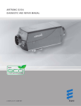
AIRTRONIC D2/D4
Installation, Troubleshooting & Parts Manual
Espar
AIRTRONIC
AIRTRONIC
AIRTRONIC
AIRTRONIC
AIRTRONIC
D2 - 12 volt
D2 - 24 volt
D4 - 12 volt
D4 - 24 volt
For Heater Models
Release period
25 2069 05 00 00
25 2070 05 00 00
25 2113 05 00 00
25 2114 05 00 00
November 2001
November 2001
November 2001
November 2001
P/N: 610-103-0901
November 2001
Table of Contents
Page
Introduction
Heater Warnings
Introduction
Specifications
Principal Dimensions
Heater Components
........................................................
........................................................
........................................................
........................................................
........................................................
3
4
5
6
7
Installation Procedures
Heater Location
Heater Mounting
Heater Plate installation
Mounting Pattern
Ducting Components
Heater Air Ducting
Fuel System
Electrical Connections
Exhaust/Intake Connections
Operating Switches
........................................................
........................................................
........................................................
........................................................
........................................................
........................................................
........................................................
........................................................
........................................................
........................................................
8
8
8
9
9
9
10
12
13
13
Heater Operation
Switch on
Start-Up
Temperature setting
Temperature Control
Switching Off
Controls & Safety Equipment
Operational Flow Chart
Function Diagrams
Schematic AIRTRONIC D2/D4
........................................................
........................................................
........................................................
........................................................
........................................................
........................................................
........................................................
........................................................
........................................................
14
14
14
15
15
15
15
16
17
Maintenance,
Troubleshooting &
Repairs
Periodic Maintenance
Basic Troubleshooting
Self Diagnostic Troubleshooting
Fuel Quantity Test
Overheat/Flame sensor values
Control and Resistance values
Repair Steps
........................................................
........................................................
.......................................................
........................................................
........................................................
........................................................
........................................................
18
18
18
23
23
24
25
Heater Parts
AIRTRONIC D2/D4
-Service Parts Diagram
AIRTRONIC D2/D4
-Parts List
........................................................
30/32
........................................................
31/33
Special Notes
Note: Highlight areas requiring special attention or clarification.
Caution: Indicates that personal injury or damage to equipment may occur unless specific guidelines are followed.
Warning: Indicates that serious or fatal injury may result if specific guidelines are not followed.
This publication was correct at the time of going to print. However, Espar Inc. has a policy of continuous improvement
and reserves the right to amend any specifications without prior notice.
3
Heater Warnings
Warning To Installer:
Correct installation of this heater is necessary to ensure
safe and proper operation.
Read and understand this manual before attempting to
install a heater.
Warning - Explosion Hazard
1.
Heater must be turned off while re-fueling.
2.
Do not install heater in enclosed areas where
combustible fumes may be present.
3.
Do not install heaters in engine compartments of
gasoline powered boats.
Warning - Fire Hazard
1.
Install heater so it will maintain a minimum distance of
2” from any flammable or heat sensitive material.
2.
Install the exhaust system so it will maintain a
minimum distance of 2” from any flammable or heat
sensitive material.
3.
Ensure that the fuel system is intact and there are no
leaks.
Failure to follow these instructions could cause fire resulting in serious or fatal injury.
ATTENTION
Operation with bio-diesel
AIRTRONIC D2
AIRTRONIC D2 is not certified for use with bio-diesel.
Admixtures of bio-diesel up to a magnitude of approx. 10%, as
in some countries, are allowed.
AIRTRONIC D4
AIRTRONIC D4 is certified for operation with bio-diesel as per
DIN V 51606 in free-flowing state when installed in “normal
horizontal position (exhaust pipe downwards)”; bio-diesel is not
permitted for any other installation positions.
When using 100% bio-diesel, AIRTRONIC D4 should be oper ated with pure diesel fuel twice per year, preferably in the middle and at the end of a winter period, to burn off any possible
PME residues: For this purpose, drain your vehicle tank as far
as possible (caution: do not forget to leave enough fuel in the
tank to get to the next fuel station!) and then fill the tank with
pure diesel fuel without bio-admixture.
While using this tank filling, let AIRTRONIC D4 run at the maxi mum temperatures pre-selection stage at least twice or three
times for 30 minutes at a time. You can use this for example to
pre-heat your vehicle before setting off. After this “diesel operation” of your AIRTRONIC D4, you can use bio-diesel again as
required.
When using mixtures of diesel / bio-diesel with up to 50% bioshare, it is not necessary to use pure diesel fuel now and then.
Warning - Asphyxiation Hazard
1.
Route the heater exhaust so that exhaust fumes can
not enter any passenger compartments.
2.
Ensure an air tight seal will be maintained between
the heater and mounting surface and at any exhaust
connection points.
3.
Ensure that heating air supply is taken from an area
where poisonous gases will not be present.
4.
If running exhaust components through an enclosed
compartment, ensure that it is vented to the outside.
Failure to follow these instructions could cause oxygen
depletion resulting in serious or fatal injury.
ATTENTION
Heating at high altitudes
Up to 1500 meters - unrestricted heating operation is possible
Above 1500 meters - heating operation is in principle possible
for short periods, e.g. when crossing a mountain pass of during
a brief stop. In cases of extended stays , the fuel supply at the
fuel metering pump has to be adapted to high altitude conditions. Please call
USA
1-800-387-4800
CDA
1-800-668-5676
for special circumstances.
Direct questions to Espar Heater Systems
USA
1-800-387-4800
CDA
1-800-668-5676
4
Introduction
Espar ‘s AIRTRONIC bunk heaters
The AIRTRONIC D2 is a compact diesel-fired 7,500 BTU/hr air
heater, quality engineered to provide a dependable means of
space heating. This heater is uniquely designed for inside
mounting and ease of installation. The AIRTRONIC D4 is a
12,000 BTU/hr air heater for larger bunks.
These heater provide hot air to the interior of vehicles
for passenger comfort. Since the heater runs on diesel
fuel and 12 or 24 volt power, it is able to provide space
heat completely independently of the vehicle engine.
The heater is operated by a rheostat switch or room thermostat. It cycles through four temperature settings (boost-highmedium-low) in order to maintain the desired temperature.
If, in special cases, less heating capacity is required than
the heater supplies in the “Low” setting, the heater switches to
a “stand-by” setting. Temperature and overheat sensors, and a
specially designed heat exchanger are among the safety features which make this heater a safe and dependable unit.
For illustration purposes only
5
Specifications
AIRTRONIC D2
AIRTRONIC D4
Heat Output (±10%)
7,500 BTU/hr Boost (2.2 kW)
6,150 BTU/hr High (1.8 kW)
4,100 BTU/hr Medium (1.2 kW)
2,900 BTU/hr Low (0.85 kW)
13,650 BTU/hr Boost (4.0 kW)
10,200 BTU/hr High (3.0 kW)
6,800 BTU/hr Medium (2.0 kW)
3,400 BTU/hr Low (1.0 kW)
Current at 12v (±10%)
8.3 amps - Start
2.8 amps - Boost
1.9 amps - High
1.0 amps - Medium
0.7 amps - Low
8.3 amps - Start
3.3 amps - Boost
2.0 amps - High
1.1 amps - Medium
0.6 amps - Low
Current at 24v (±10%)
4.2 amps/hr - Start
1.4 amps/hr - Boost
1.0 amps/hr - High
0.5 amps/hr - Medium
0.3 amps/hr - Low
4.2 amps/hr - Start
1.7 amps/hr - Boost
1.0 amps/hr - High
0.5 amps/hr - Medium
0.3 amps/hr - Low
Fuel Consumption (±10%)
Boost
High
Medium
Low
U.S.
Gal/hr
Litre/hr
0.07
0.06
0.04
0.03
0.28
0.23
0.14
0.10
Boost
High
Medium
Low
U.S.
Gal/hr
Litre/hr
0.13
0.10
0.07
0.03
0.51
0.38
0.25
0.13
Air Flow (±10%)
48 cfm Boost
40 cfm High
27 cfm Medium
19 cfm Low
85 cfm Boost
69 cfm High
50 cfm Medium
30 cfm Low
Operating Voltage Range
10.5 - 16 vdc at 12 vdc
21 - 32 vdc at 24 vdc
10.5 - 16 vdc at 12 vdc
21 - 32 vdc at 24 vdc
Overheat Temperature
Shutdown (±10%)
240°F (115°C)
240°F (116°C)
Ambient Operating
Temperature
-40°F to 158°F (-40°C to 70°C)
-40°F to 158°F (-40°C to 70°C)
Weight
6.0 lbs. (2.7 kg)
9.9 lbs. (4.5 kg)
Note: The heater control unit is equipped with a low
voltage cutout to prevent vehicle battery drain and
a high voltage cutout to protect heater electrical
parts.
6
* All measurements in millimeters
25.4 mm = 1”
Minimum installation distance
(clearance) to open the lid and to
dismount the glow pin and the
control unit.
Principal Dimensions AIRTRONIC D2
Minimum installation distance
(clearance) to take in heating air.
(12.2 inches)
(4.5 inches)
Principal Dimensions AIRTRONIC D4
(14.8 inches)
(5.5 inches)
7
Heater Components
1 Hot Air Blower Wheel
2 Control Unit
3 Combustion Air Blower Wheel
4 Glow Pin
5 Cover
6 Heat Exchanger
7 Overheat/Flame sensor
8 7 Day Timer with thermostat (optional)
9 Operating Unit (Thermostat)
10 Operating Unit (Rheostat)
11 Blower Motor
12 Fuel Connection
13
14
15
16
17
18
19
20
21
Flange Seal
Combustion Chamber
Hot Air Outlet Hood
Combustion Air Intake Hose
Fuel Metering Pump
Fuel Filter built into FMP
Hot Air Output Deflector
Flexible Exhaust Pipe
Main Fuse: AIRTRONIC D2 - 20 A
AIRTRONIC D4 - 10 A
C = Combustion Air
D = Fuel Intake from tank
E = Exhaust
F = Fresh Air Intake
H = Hot Air Output
8
Installation Procedures
Heater Mounting Plate Installation
Heater Location
Depending on the type of vehicle, the best location for mounting the heater will vary. Typically, air heaters are mounted
inside tool or luggage compartments. However, the heater may
be mounted anywhere inside the vehicle provided you adhere
to the following conditions:
Silicon gasket (flange)
Stainless Steel Plate
Plate seal
Hex Head Tek Screw
• Combustion air intake, exhaust and fuel inlet must be
located outside of the vehicle.
• Heater must be mounted on flat horizontal surface
providing an air tight seal between heater and vehicle.
• Do not mount the heater outside the vehicle, unless care is
taken to protect the heater from the weather. When selecting
the location, consider the following:
• Combustion air and exhaust connections.
• Ducting.
• Fuel line connections.
• Electrical connections.
Flat washer
Nut
Cab Floor
Spring Washer
Note: Tighten screws sufficiently to ensure positive seal
between mounting plate and mounting surface.
Do not over tighten.
Heater Mounting
A mounting plate and hardware are provided with the truck
heater kit.
• Choose heater location.
• Using template provided, drill and cut center hole. Cut (1)
four and one half inch (4 1/2”) diameter hole or one rectangular hole four (4”) by five (5”) inches to accommodate
mounting plate and seal. Secure mounting plate to vehicle
floor with “Tek” screws provided.
• Use Heater flange as a template if not using mounting plate
and seal
• Mount heater on mounting plate with nuts and spring
washers provided.
• For ease of installation make the exhaust, combustion air
intake and fuel connections at base of heater before mounting the heater into the vehicle. See following pages for
instructions and restrictions on exhaust, combustion and fuel
hook-ups.
Heater
Flange
Wiring Harness
Right or Left
Stainless Steel
Mounting Plate
and seal
Wiring harness connection, right or left
Wiring harness can be converted to the opposite side of the
heater if it makes the installation more practical. To do this you
must remove the AIRTRONIC cover and then the control unit.
On the control unit (underneath) is a semicircular clip protecting the harness. This must be removed. The harness should be
moved to the other side of the control unit then reassembled.
The grommet on the heater casing (side) must also be taken
out and secured into the opposite lower side of heater casing.
Exhaust
Tubing
Combustion
Air intake
Fuel line
9
Mounting Pattern
inches
millimeters
Heater Air Ducting Installation
A 60mm flexible duct 40 inches long, hot air outlet and clamps
are provided with the heater kit. In routing and installing the
ducting the following criteria must be observed:
•
•
•
•
•
Route ducting with smooth bends. Avoid crushing duct.
Position hot air outlet so that it cannot be obstructed.
When not using return ducting. Use a protective air intake
grille on air inlet side of heater to prevent objects from
being sucked in.
Ensure provisions are made for proper air return ventilation.
Use return air ducting for best heating efficiency.
Return Ducting
For illustration
purposes only
No Return Ducting
For illustration
purposes only
Ducting Components
1. Protective Grill
2. Air Outlet Hood AIRTRONIC D2 - ø60 or75mm
AIRTRONIC D4 - ø75 or 90mm
3. Hose Clamp 2-2 3/4”
4. Flex Duct 2 3/8” (ø60 or 75mm) (ø90mm on D4)
Warning: Do not use existing vehicle ducting or outlets.
Ducts and outlets must be capable of withstanding a minimum of 300°F operating temperatures.
5. Air Outlet - Rotatable
6. Connection Piece
7. Protective Grill
8. 90° Bend Ducting 2 3/8”
Caution:
Do not over tighten duct clamps.
Do not position outlet so that it will blow hot air
directly at operator or at room thermostat.
10
Fuel System
The fuel metering pump is the heart of the system and must be
installed properly to ensure a successful heater operation.
Fuel System Overview
7
6
Max. 20’
Max. 6’6”
8
6
7
2
5
3
Max. 6’6”
4
Max. 2’6”
5
Max. 2’
2
3
9
3
Fuel
Tank
1
3
Fuel
Tank
1
Optional
Note: Butt joints and clamps on all connections.
1. Fuel Pick-Up Pipe
2. 5.0 Rubber Connector
3. 11mm Clamp
4. 2.0mm Black Plastic Fuel Line
5. Fuel Metering Pump
6. 9mm Clamp
7. 3.5mm Rubber Connector
8. 1.5mm White Plastic Fuel Line
9. 5mm Rubber Fuel Line
Fuel Pick-Up Pipe Installation (Standard Pick-Up)
•
•
•
•
•
•
•
Choose a protected mounting location close to the fuel
pump and heater. A spare fuel sender gauge plate provides an ideal mounting location.
Drill the mounting holes as shown
Cut the fuel pick-up pipe to length.
Mount the fuel pick-up pipe as shown.
Lower the fuel pick-up pipe (with reinforcing washer) into
the tank using the slot created by the two 1/4” holes.
Lift the assembly into position through the 1” hole.
Assemble the rubber washer, metal cup washer and nut.
Note: Drill the two 1/4” holes first.
Optional
11
NPT fitting and pipe
optional
Custom Pick-Up Pipe with NPT fitting - optional
•
Remove an existing plug from the top of the fuel tank.
•
Cut the fuel pick-up pipe to length.
•
Secure the fuel pick-up pipe into position using the
combined NPT compression fitting
Note: NPT fittings are available in various sizes (Refer
to parts section).
Fuel Metering Pump
•
Choose a protected mounting location close to the fuel
pick-up pipe and heater if not using standard assembly as
shown on right.
•
Using the bracket and rubber mount provided, install fuel
pump as shown
Note: Proper mounting angle of the fuel pump is
necessary to allow any air or vapor in the fuel
lines to pass through the pump rather than cause
a blockage.
Fuel Line
•
Route fuel lines from the fuel pick-up pipe to the fuel
metering pump then to the heater.
•
Use fuel lines provided.
•
Other sizes or types of fuel lines may inhibit proper
fuel flow.
•
Make proper butt joints using clamps and connector
pieces as shown on previous page
•
Use a sharp utility knife to cut plastic
fuel lines to avoid burrs and pinching
fuel line shut.
Typical standard assembly, if
not using this format please
adhere to specifications on
pg.10
12
Electrical Connections
Main Harness.......................................................................
16 pin connector with 10 terminated wires at 8 terminals.
(green/red, blue/white (2), red, grey/red, grey, brown,
brown/white and yellow (2)).
Connect to the heater ’s 16 pin connector
Connect other harnesses as described below
Power Harness.....................................................................
2 core harness (red and brown).
Route power harness to batteries, cut to length and terminate
as described below. Install 20 amp fuse last. (10 amp on 24V).
Connect red wire to fuse holder near battery.
Connect fuse link wire directly to battery positive post using
ring terminal.
Connect brown wire directly to battery negative post using ring
terminal.
Switch Harness....................................................................
7 core harness (red, brown/white, yellow, grey, brown, grey/red and
blue/white)
Route this harness the length required to reach thermostat
installed in bunk compartment. Do not cut this harness, wires have
been soldered at ends for convenience of terminating to terminals
on thermostat. Coil up excess harness and secure in safe location.
Connect to thermostat or rheostat switch (refer to switch connection section).
2 core harness (green/red and brown).
Route this harness from heater to fuel metering pump. Cut to
length and connect to fuel metering pump using single terminals and connector provided with kit. (no polarity required).
Fuel Metering Pump Harness.............................................
Diagnostic Harness.............................................................
4 pin on 8 pin connector.(red, brown, yellow, blue/white
For diagnostic purposes only.
Caution: Install power 20 amp fuse only after all electrical
connections are complete. 10 amp on 24V.
Note: All exposed electrical connections should be coated with protective grease, (petroleum gel,
Vaseline, etc.).
Main Harness
Fuel Metering Pump Harness
Connector for Diagnostics
Fuse and holder
Switch Harness
Thermostat
Power Harness
13
Exhaust and Combustion Air Intake Connections
Operating Switches
A 24mm flexible stainless steel exhaust pipe (39”long) and a
25mm flexible plastic tube (39” long) for combustion air intake
are included with the heater kit. Exhaust clamps and holders
are also provided.
The heater can be controlled using a Thermostat or Rheostat
type switch. It can also be controlled by a 7 day timer with thermostat. See schematic pg. 17.
Thermostat
Caution:
•
•
•
•
•
Route exhaust and combustion air intakes so they
cannot be plugged by dirt, water or snow.Ensure the
outlets do not face into the vehicle slip stream.
Keep exhaust and combustion air intake a minimum
of 12” apart.
Drill 1/8” holes in exhaust pipe if necessary to allow
water drainage.
Combustion air intake and exhaust lengths can be
shortened to a minimum of 8”.
Attach the exhaust pipe to the exhaust outlet of the heat
exchanger
Route exhaust pipe to an open area to the rear or side of
the vehicle so that fumes cannot build up and enter the
cab or the combustion air inlet to the heater.
Install protective cap.
Attach the combustion air intake tube to the combustion
air inlet of the heater
Once secure to the heater inlet, the intake pipe must be
routed to the underside of the vehicle where it will pick up
clean, fresh, moisture free air.
•
•
•
•
Select a mounting location which will be representative of
the average temperature of the area being heated. Avoid
mounting near heater outlets, windows, doors, electrical
appliances or in areas receiving direct sunlight.
Route the switch harness from the heater to the thermostat mounting location.
Mount the thermostat as shown using proper mounting
hardware and the slots provided on the thermostat base.
Pull the switch harness through the
thermostat base access hole.
Connect the six core switch harness to the thermostat as
shown
Mounting slots
Thermostat base
access hole
End Cap
This wire is “optional”
•
Exhaust ( min. 8” - max. 6.5’).
•
•
•
Combustion Air Intake
( min. 8” - max. 6.5’).
End Cap
Warning:
The exhaust is hot, keep a minimum of 2”
clearance from any heat sensitive material
Warning:
Route exhaust so that the exhaust fumes
cannot enter the passenger compartment.
It is recommended that when using return ducting, not to
use this wire. See illustration on pg. 9 for ducting.
Not using the grey wire defaults the heater to use the temperature sensor on the control unit of the heater.
Use of the grey wire defaults the heater to use the sensor
on the thermostat.
The sensor on the control unit provides a more accurate
reading of the overall air temperature, whereas the sensor
in the thermostat gives more of a spot reading of the air
surrounding the thermostat.
Temperature sensor on
AIRTRONIC control unit.
14
Rheostat Switch
Note: When using Rheostat switch, the Return Ducting
method must be used as shown on page 9. This
allows the AIRTRONIC heater’s internal sensor to
properly monitor cab temperature.
•
•
•
Mount the rheostat switch in a location
where it is easily accessible.
Route the switch harness from the
heater to the Rheostat mounting location.
Connect the six core switch harness
as shown
Temperature sensor on
AIRTRONIC control unit.
Heater Operation
Warning: To prevent fire, the heater must be switched
off while filling fuel tanks.
To prevent asphyxiation, the heater must not
be operated in enclosed areas unless heat
exhaust is routed to outside of garage bay.
1
Switch On
•
Switch the heater on using the room thermostat’s, On/Off
switch (1=On, 0=Off ) or the rheostat switch.
2
Start Up
3
Temperature Setting
Using the adjusting dial, set the desired temperature range.
•
Lowest Setting - approx. 10°C (50˚F)
•
Mid - Setting - approx. 20°C (68˚F)
•
Highest Setting - approx. 30°C (86˚F)
On/Off switch
Green diagnostic light
Red operating light
On start up the indicator light illuminates and the following
sequences take place:
•
Control unit does a systems check of the glow pin, flame
sensor/temperature sensor, fuel metering pump and con trol unit.
•
Blower starts slowly and begins to accelerate.
•
Glow pin is energized and starts preheating the combustion chamber.
•
After a delay (approx. 60 seconds) the fuel pump delivers
fuel.
•
Ignition will take place as the fuel/air mixture contact the
glow pin.
•
Blower speed and fuel delivery are slowly increased.
•
Once flame sensor has detected a flame the glow pin will
switch off, after approx. 60 secs.
•
After another 120 secs., heater will have reached maximum power.
On OEM installs the ‘red” & “green” indicator lights illuminate.
On after market installs only the “Red” light illuminates.
Operation indicating light
Low
High
15
4.
Temperature Control
6
Controls and Safety Equipment
•
The temperature is monitored constantly at the heater’s
process air inlet or thermostat.
•
This temperature is compared to the set temperature on
the adjusting dial.
If the heater fails to ignite within two 90 second start
attempts, a "no start" shut down occurs.
•
The heater cycles through Boost, High, Medium and Low
heat modes to maintain the desired temperature.
If a flame out occurs after the heater has started, the
heater will attempt to restart.
•
If the desired temperature is exceeded while the heater is
operating in low heat mode the heater will switch into
“standby” mode. This is a comfort feature.
If repeated flame outs occur within 15 minutes the heater
will not restart.
•
Overheat shut down will occur if there is a restriction of the
heating air flow (i.e. blocked inlet or outlet). The overheat
sensor will automatically reset once the heater has cooled
down.
•
Once the air flow restriction is removed, the heater can be
re-started by switching the heater off then back on.
•
If the voltage drops below 10.5 volts or rises above 16
volts the heater will shut down (21 volts and 28 volts for 24
volt systems).
If the glow pin circuit or fuel metering pump circuit are
interrupted the heater will not start.
•
•
•
•
The heater will re-start in once heat is again required.
5
Switch Off
Once switched off either manually or automatically, the heater
begins a controlled cool down cycle.
•
•
Indicating light(s) on switch will go off
•
Fuel pump stops delivering fuel.
•
The glow pin is re-energized for a 40 second after-glow to
burn off any combustion residue.
•
The blower continues to run for 4 minutes and automatically switches off.
Operational Flow Chart
•
The blower motor is checked on start
up and continuously during operation.
Shut down will occur if the blower does
not start or maintain proper speed.
16
Function diagram AIRTRONIC D2
Function diagram AIRTRONIC D4
17
Schematic AIRTRONIC D2 / AIRTRONIC D4
Wire color key
for switches
red
yellow
brown
grey
Designation
=
=
=
=
grey/red =
blue =
blue/white =
brown/white =
black =
1.1
1.2
1.5
2.1
2.2
2.7
3.1.11
3.2.8
3.5
5.1
6.1
Blower Motor
Glow Pin
Overheat and Flame sensor
Control Unit
Fuel Metering Pump
Main Fuse 12Volt - 20 amp / 24 volt - 10 amp
Rheostat
7 Day Timer
Thermostat
Battery
Diagnostic Pigtail (for connection to Fault code retrieval device)
power (+)
switch
ground (-)
temperature sensor
on thermostat
*vehicle dimmer switch
for light display on
7-day timer
temperature setting
diagnostic
from heater
diagnostic
from heater
ground
to vehicle ignition
accessories for continuous
operation of heater
18
Maintenance
Basic Troubleshooting
Recommended Periodic Maintenance
Check LIst:
•
Remove the glow pin and inspect for carbon build up.
Clean or replace.
What happens when the heater is switched on and ....
•
Remove the glow pin screen and inspect for carbon build
up. Clean or replace.
Heater does not ignite
•
Make sure vent hole is open. Espar recommends the use
of non detergent 100% volatile carburetor cleaner, an air
gun will also help. Remove loose carbon from the glow pin
chamber.
•
Inspect the ducting, the air intake screen and air outlet for
restriction or blockage.
•
Inspect combustion air intake and exhaust for blockage.
•
Operate your heater for a minimum of 20 minutes each
month
•
Maintain your batteries and all electrical connections in
good condition. With insufficient power the heater will not
start. Low and high voltage cutouts will shut the heater
down automatically.
•
Use fuel suitable for the climate (see engine manufacturers recommendations). Blending used engine oil with
diesel fuel is not permitted.
1 Blower motor does not run
Check:
- Fuse in power harness.
- Power to control unit.
- Power to and from switch.
- Electrical connections.
2 Blower motor runs approximately 20 seconds and then
shuts off
Check:
- Ensure voltage at control unit remains
above 10 volts during start up with glow
plug circuit on.
3 Blower motor runs/fuel metering pump starts and then
shuts down after two start up attempts
Check:
- Fuel lines and fuel filter.
- Fuel quantity. Pg. 23
- Combustion air or exhaust tube blockage.
4 Blower motor runs/ no fuel metering pump
Check:
- For electrical pulses at fuel metering
pump.
- If pump is frozen.
- Blocked fuel line.
Heater ignites
1 Shuts down at random
Check:
- Fuel metering pump quantity. Pg. 23
- Possible overheat.
- Control unit input voltage.
2 Heater smokes and carbons up
Check:
- Exhaust pipe blocked.
- Combustion air intake blocked.
- Exhaust entering combustion air intake
pipe.
- Short cycling, rapid on/off operation.
- Fuel system.
- Fuel metering pump quantity.
- Motor rpm.
19
Self Diagnostics
The heater is equipped with self diagnostic capability. To
retrieve information on the heater ’s last 5 faults, a retrieval
device is required (part # CA1 05 020). There is a pig tail to
accommodate the connector on the main harness from
heater. If wire pigtail is not present, a wiring
adapter (P/N: 22 1000 31 86 00) must be used.
Connect the fault code retrieval device as shown. This device
enables these four functions to be performed.
1.
2.
3.
4.
Access the current fault which is affecting the heater
Access the four previous faults which affected the heater.
Clear the fault memory to erase previous fault history
Unlock “lockout features” which exist for some control
units.
Equipment Face and Controls
Symbols that are seen on the display face are as follows:
AF
Actual fault.
F1-F5
Up to five stored faults can be accessed.
The AF and F1 are the same number.
On/Off
This sign is displayed when the heater is in
operation.
Retrieval Device
DIAG
The word (DIAG) nostic will come on when
the diagnostic number is requested.
000
Three digit diagnostic fault code number.
On/Off switch
•
Switch the fault code retrieval device on and wait 10
seconds.
•
Press the "D" button.
•
Wait 3-5 seconds for the current fault code to appear (AF).
•
To review the previous faults use the arrow buttons
(F1= Most Recent, F5= Oldest).
•
Consult the fault code chart for code number descriptions.
•
To erase the faults that are in memory press both "L" keys
at the same time for 5 seconds. This will also a unlock the
control unit.
20
Note: If there are no heater faults, the heater will go through
a normal start cycle and regulate based on thermostat
setting.
Fault Code
See schematic
pg. 17
Fault Description Causes / Repair
000
Normal Operation
004
Warning - short circuit in controller, fresh air-outlet
Disconnect connection S1/B1 at AIRTRONIC. At connector B1, pin 16
check for short between pin and blower relay. If no short exists replace
control unit.
005
Warning - short circuit at controller - anti-theft alarm output
Disconnect connection S1/B1 at AIRTRONIC. At connector B1, pin 16
check the line through to the relay isolating switch or theft warning in
line for short circuit to chassis. If no short exists replace control unit.
009
TRS - shut down
Switch off due to signal change.Check for change of signal from (+) to
(-) at pin 13 (S1) or a (+) signal at pin 14 (S1).
010
Overvoltage
Start vehicle motor. Check voltage at (B1) between terminals 1 and 10.
This must be less than 16 volts (15.2 volts with glow plug on). Check
vehicle charging system.
AIRTRONIC 24 volt - voltage must be less than 32 volts
011
Undervoltage shut down
Start vehicle motor. Check voltage at connector (B1) between terminals
1 and 10. This must be more than 10 volts. Check vehicle charging
system. Check batteries and connections.
AIRTRONIC 24 volt - voltage must be more than 21 volts.
012
Overheat at overheating sensor
Sensor has detected excessive temperatures. Check for clogged hot air
ducting. Check that the the total number of ducting pieces in unison is
not too large. Re-route if necessary. Check overheat sensor resistance
values. (see component value chart pg 23). If O.K. Measure fuel quantity. See page 23.
013
Overheat at flame sensor
Flame sensor detects excessive temperature at heat exchanger. Check
for clogged hot air ducting. Check that the the total number of ducting
pieces in unison is not too large. Re-route if necessary. Measure fuel
quantity. See page 22. Check flame sensor resistance. (see component
value chart pg 22)
014
Temperature difference between flame sensor and
overheating sensor too large
Check for clogged hot air ducting. Check that the the total number of
ducting pieces in unison is not too large. Check flame sensor, if O.K.,
check overheating sensor. If over-heating sensor defective replace
combi-sensor. If over-heating sensor O.K. measure fuel quantity. See
page 23. If fuel quantity O.K. replace control unit.
015
Overheat with excessive temperatures
Fault code 015 is shown when the AIRTRONIC is switched on again
after fault code 017. The hardware limit value for the overheating sensor, has been exceeded - control unit is damaged. Check sensor.
Replace control unit.
017
Overheat with excessive temperature
The hardware limit value for the overheating sensor, has been exceeded, because the control unit has not detected fault code 012, 013.The
control unit is locked. If AIRTRONIC is switched on again, fault code
015 is displayed. Replace control unit. Check sensor.
020
Open circuit - glow pin
Check continuity of glow pin.
AIRTRONIC 12 volt - approx. 0.5 Ω ± 0.05 Ω
AIRTRONIC 24 volt - approx. 2 Ω ± 0.2 Ω
021
Short circuit - glow pin
Check functions of glow pin in installed condition, to do so disconnect
connector from controller. AIRTRONIC 12 Volt and 24 Volt. Apply voltage of 8 / 18 volts to glow pin respectively, and measure current
intensity after 40 seconds. Glow in is O.K. for the following values:
glow pin 8 volt - current = 9 amps + 1.5 / - 1.2 amps
glow pin 18 volt - current = 4 amps ± 0.5 amps
If the values differ, replace glow pin. If the values of the continuity test
and function test are O.K., check glow pin cable harness for damage
and continuity. If O.K., replace control unit.
Caution!
For AIRTRONIC 12 volt, check functions with max. 8 volt
For AIRTRONIC 24 volt, check functions with max. 18 volt.
if voltage values are exceeded the component is destroyed.
Check sort-circuit resistance of mains unit: min. 20 Amp.
21
Fault Code
Fault Description Causes / Repair
031
Blower motor interrupted
Check blower motor cable harness for correct routing and damage. If
O.K., disconnect cable harness from control unit and check for continuity, if O.K., replace control unit.
032
Blower motor, short circuit
Check functions of blower motor, to so so, disconnect connector from
control unit. Apply voltage of 8 volts or 18 volts ± 0.1 to blower motor
and measure current intensity after 40 seconds.
Current < 6.5 amp - blower motor O.K., replace controller
Current > 6.5 amp, replace blower.
Caution!
For AIRTRONIC 12 volt, check functions with max. 8 volt
For AIRTRONIC 24 volt, check functions with max. 18 volt.
if voltage values are exceeded the component is destroyed.
Check sort-circuit resistance of mains unit: min. 20 Amp.
033
Blower motor does not turn
Motor speed varies from specification by more than 10% for longer than
30 seconds.
If too slow, check for restriction, and check for short in motor circuit or
control unit. If none found, replace blower.
If too fast, check for damage or missing magnetic sensor on control
unit. Replace blower motor if damaged.
Replace control unit otherwise.
047
Short circuit - fuel metering pump
Disconnect connector from fuel metering pump, if fault code 048 (interruption) is displayed then the fuel metering pump is defective, replace
FMP.
If fault code 047 is still displayed, then disconnect connection S1/B1. At
connector B1, Pin 5, check line1(green/red) through to FMP for short
circuit to (pin 10), if O.K. replace control unit
048
Open circuit - fuel metering pump
Disconnect connector from fuel pump and measure resistance value of
fuel pump (see values, pg 22). If resistance values O.K., then reconnect cable harness to the fuel pump. Disconnect connection S1/B1,
and measure the resistance value between pin 5 and pin 10. If O.K.,
replace control unit.
050
Too many no start attempts
Control unit is locked after too many unsuccessful start attempts. Check
fuel, glow plug, combustion air and exhaust flow. Use control unit
tester or fault code retrieval device to unlock control unit. Maximum 255
051
Faulty flame recognition
If the resistance value of flame sensor is 1274 Ω after switching on (>
70°C), then the blower of the AIRTRONIC runs for approx. 15 minutes
to cool down. If resistance does not fall below the above value within
15 mins.., this is followed by fault shut down. Check flame sensor, diagrams and values, pg 23. If O.K., replace control unit.
052
No start safety time exceeded
No flame detected on start attempt.Check exhaust and combustion air
lines. Check fuel supply/measure fuel quantity, see following pages.
Check glow pin (see fault code 020 and 021). Check flame sensor, diagram and values table on following pages, if O.K., replace control unit.
053
054
055
056
Flame cutout in boost mode
Flame cutout in high mode
Flame cutout in medium mode
Flame cutout in low mode
Heater has started successfully the flame has extinguished.
Check exhaust and combustion air lines. Check fuel
supply/measure fuel quantity, see values, pg 23. Check flame
sensor, diagram and values table on following pages, if O.K., replace
control unit.
060
Open circuit - external temperature
Temperature sensor detects a value beyond it's range sensor
Disconnect connection S1/B1 (main harness), measure resistance
value at connector B1, pins 6 & 12. Refer to the values table on pg 23.
If there is an open circuit, the ohmic value between the pins is > 7175
Ω. If the resistance value is O.K., then the control unit is defective.
061
Short circuit - external temperature
Disconnect connection S1/B1 (main harness), measure resistance
value at connector B1, between pins 6 & 12., see values on pg 23. If
there is a short circuit, the ohmic value between the pins is < 486 Ω. If
fault 061 continues to be displayed, then the control unit is defective.
22
Fault Code
Fault Description Causes / Repair
062
Thermostat/Rheostat/Timer, open circuit
Potentiometer values outside of range on Thermostat (switch)
Check resistance between pins 6 and 7 at B1.
Resistance value for interruption between pins > 7175 Ω
Normal value: 1740 Ω - 2180 Ω (± 80 Ω )
If resistance value is O.K., replace control unit. If not replace thermostat/(switch).
063
Switch control - short circuit
If a ventilating switch has been built in, disconnect and check function.
If faulty, replace switch. Disconnect wires from thermostat or switch. If
fault code 062 is displayed, replace switch. If switch is O.K., check connection lines grey/red and brown/white for short-circuit. If O.K., reconnect wires to thermostat/switch. Disconnect connection B1. If fault 063
is still displayed, replace control unit. Resistance value for short circuit
between pins 6 and 7 < 486 Ω. Normal value: 1740 Ω - 2180 Ω (± 80
Ω).
Fault recognition only works in heating mode. However, if
a short circuit already exists and the AIRTRONIC is subsequently switched on, ventilating mode will be active (no
fault code).
064
Open circuit - flame sensor
Sensor is sensing value outside of range. Open Airtronic shell and
remove control unit from casing. Disconnect green connector from control unit. At green connector measure resistance value at green wire
and brown/white wire. Check flame sensor, diagram and values on pg.
23. If flame sensor is O.K., replace control unit. Resistance value for
interruption > 7175 Ω
065
Short circuit - flame sensor
Open Airtronic shell and remove control unit from casing. Disconnect
green connector from control unit. If fault 064 is displayed, replace
combination sensor (flame/temperature). If fault 065 is still displayed,
replace control unit. Resistance value for shot circuit < 486 Ω, see values on following pages.
071
Open circuit - overheat sensor
Open Airtronic shell and remove control unit from casing. Disconnect
blue and green connectors from control unit. Measure the resistance
value at blue connector(pin 1- blue wire) and at green connector pin 2
(brown/white wire). See values on following pages. If O.K., replace control unit. Resistance value for interruption > 223 Ω.
072
Short circuit - overheat sensor
Open Airtronic shell and remove control unit from casing. Disconnect
blue connector from control unit. If fault 071 displayed, replace combination sensor (flame/temperature). If fault 072 is still displayed, replace
control unit. Resistance value for short circuit < 183 Ω, see following
pages for values.
090
Control unit defect
Internal failure. Replace control unit.
091
External voltage disturbance
Check vehicle charging system. Poor battery, battery charger, eliminate
fault.
092
Control unit defective (ROM fault)
Internal failure. Replace control unit.
094
Control unit defective (EEPROM fault)
Replace control unit
096
Internal temperature sensor defect
Replace control unit or use external temperature sensor.
097
Control unit defective (power failure)
Internal failure. Replace control unit.
23
Fuel Quantity Test
Values for Overheat sensor
The fuel quantity should be tested if the heater has difficulty
starting or maintaining a flame. Check the following before
measuring fuel quantity.
•
•
•
•
•
Check the filter in the fuel pump
Check that the fuel lines are correctly routed
Check that the fuel lines don’t leak.
Check and tighten hose connections
Does fuel withdrawal comply with the data in the technical
description.
Preparation
•
Detach the fuel line from the AIRTRONIC.
•
Insert the fuel line into a measuring glass (25 cm3).
•
Switch the AIRTRONIC on and allow fuel system to bleed
out air for approx. 60 seconds.
•
Switch the AIRTRONIC off and drain the measuring glass.
Measurement
•
Switch the AIRTRONIC on
•
The fuel is pumped approx. 60 seconds after switching on.
•
Hold the fuel line in the measuring glass level with the
glow pin while fuel is being delivered.
•
The pump will stop automatically after delivering fuel for 90
seconds. (110 seconds for AIRTRONIC 4)
•
Once fuel pump stops, switch off the heater.
Temperature (°C)
Temperature °C
min.
max.
-40
-20
Resistance kΩ
1597.0
458.80
1913.0
533.40
0
154.70
175.50
20
40
60
59.30
25.02
11.56
65.84
28.04
13.16
80
100
120
5.782
3.095
1.757
6.678
3.623
2.081
140
1.050
1.256
160
180
0.6654
0.4253
0.792
0.5187
200
0.2857
0.3513
Evaluation
•
Read out the quantity of fuel in measuring glass.
•
Fuel quantity should be between
Values for Flame sensor
3.7 ml and 4.3 ml. on AIRTRONIC 2
5.4 ml and 6.3 ml. on AIRTRONIC 4
•
If the fuel quantity is outside this range, check for and
remove any restriction in fuel system or replace the fuel
metering pump.
Note: The fuel quantity is not affected by voltage variances.
Temperature (°C)
Temperature °C
-40
0
40
80
120
160
200
240
280
320
360
400
Resistance kΩ
min.
825.90
980.00
1132.30
1282.80
1431.50
1578.30
1723.40
1866.60
2008.10
2147.70
2285.50
2421.50
max.
859.60
1020.00
1178.50
1335.10
1489.90
1642.80
1793.70
1942.80
2090.00
2235.40
2378.80
2520.30
24
Control values
Motor speed
Control stage
• Power
• Fast
• Medium
• Slow
• Adjustment
- in circulation mode with temperature sensor, internal
- In fresh air mode with temperature sensor, external
• Ventilation
AIRTRONIC D2
4800 U/min ± 140 U/min
4000 U/min ± 120 U/min
2800 U/min ± 80 U/min
2000 U/min ± 60 U/min
AIRTRONIC D4
4400 U/min ± 130 U/min
3600 U/min ± 100 U/min
2800 U/min ± 80 U/min
1600 U/min ± 50 U/min
600 U/min ± 20 U/min
0 U/min
4800 U/min ± 140 U/min
600 U/min ± 20 U/min
0 U/min
3600 U/min ± 100 U/min
Resistance values
Component
AIRTRONIC D2 -12V
AIRTRONIC D2 -24V
AIRTRONIC D4 -12V
AIRTRONIC D4 -24V
Blower motor
0.6 Ω ± 0.1 Ω
2 Ω ± 0.4 Ω
0.4 Ω ± 0.1 Ω
1.5 Ω ± 0.3 Ω
Glow plug
0.5 Ω ± 0.05 Ω
2 Ω ± 0.2 Ω
0.5 Ω ± 0.05 Ω
2 Ω ± 0.2 Ω
Fuel metering pump
10 Ω ± 0.5 Ω
36 Ω ± 1.8 Ω
10 Ω ± 0.5 Ω
36 Ω ± 1.8 Ω
Operator control unit
set value potentiometer
1750 - 2080 Ω ± 80 Ω
1750 - 2080 Ω ± 80 Ω
1750 - 2080 Ω ± 80 Ω
1750 - 2080 Ω ± 80 Ω
Switching value
Component
AIRTRONIC D2 / D4
Overheating sensor
160°C - 170°C
measured in the control
stage “power”and at a
clearance of 300 mm
from the hot air outlet
Exhaust value
AIRTRONIC D2 / D4
CO2 in exhaust in control stage “fast”
7.5 -12.5 Vol. %
Soot number as per Bacharach
<6
300 mm
25
Repair Instructions
Removing the cover
Removing and checking the control unit
Removing the glow pin
Removing the lining
Removing and checking the overheating and flame sensor
Installing the overheating and flame sensor
Caution: Remove power from the heater prior to any disassembly by unplugging main connection or removing
main fuse.
Carefully check all seals and O-rings and replace
where necessary
Clean all parts before reassembly and check for
any signs of damage, replace where necessary
Dismantling the heat exchanger
Removing the combustion air blower
Removing the combustion chamber
Removing the cover form the AIRTRONIC
Unlock both seal plates, lift cover and pull to the front.
Note:
The cover must always be removed from the AIRTRONIC for
all repair stages. You may have to wait for the device to cool
down.
The cable harness can exit from the left or right of heater shell.
Cover
Seal Plates
Removing the control unit
Remove the AIRTRONIC cover
Unscrew fastening screw, press retaining brackets together, lift
out control unit. Unclip the lines from the holder of the control
unit (observe the positions of the lines). Remove the bushing
(lower part) from the outer case. Disconnect the control unit
from the controller. The control unit can now be removed.
Note:
When reassembling the control unit, ensure that the lines are
correctly clipped in the holder of the control unit, and that the
connectors are plugged into the control unit (non-interchangeable).
Fastening screw
Retaining brackets
Control unit
Bushing
Checking the control unit.
A test instrument is necessary to check the control unit in a dismantled state. The test instrument is connected up to the PC
and with special software can display run times on certain
parts and give a visual of heater in operation.
Part number 22 1524 89 00 00
Adapter P/N: 22 1000 3186 00
1.
2.
26
Heater Casing Disassembly
•
•
remove the AIRTRONIC cover
remove the control unit.
Disconnect the connector of the glow pin cable harness from
the controller.
Remove the rubber bush and use the special tool (SW 12) to
unscrew the glow pin.
The special tool is included with the glow pin.
Tighten torque of the glow pin : 6 +0.5 Nm
Note:
When the glow pin has been removed, check the lining of the
support in installed state for any contamination. The lining must
be replaced if the surface is covered with dirt.
Glow Pin
Connector of glow pin cable harness
Rubber bushing
Removing the lining
Pull the lining out of the support with pointed pliers. Blow out
the support with compressed air.
If necessary, carefully pierce with a wire.
The special tool has to be used to install the new lining. The
special tool is included with the lining. Push the lining onto the
special tool, watching the position of the recess. The recess
must be position at right angles (90°) to the axis of the heater
Push the tool with the lining carefully as far as it will go, ensuring that the bore (ø 2.7 mm) for the glow plug ventilation is
free. See illustration 1
Special tool with lining
Position of recess
Lining
Bore (Ø 2.7 mm) for glow pin ventilation
illustration 1
27
Removing the overheating sensor / flame sensor
•
•
Remove the AIRTRONIC cover
Remove the control unit
Disconnect both connectors of the overheating / flame sensor
cable harness from the control unit.
Unlock clip from sensor.
Remove overheating/flame sensor.
Cable harness for overhear/flame sensor
clip
Checking the overheating / flame sensor
Observe a maximum temperature of 320° C for checking the
sensor
Overheating sensor
Check the overheating sensor with a digital multimeter. If the
resistance value is outside the set point indicated in the values,
on pg.22 then the sensor must be replaced
Flame Senor
Check the flame sensor with ta digital multimeter. If the resistance value is outside the set point indicated by the values
table on pg 22, then the sensor must be replaced.
Installing the overheating / flame sensor
Special tool - only for AIRTRONIC D2
Overheating sensor / flame sensor
For AIRTRONIC D2 (Assembly without using purpose made
tool)
Mount the special tool on the sensor
Place the sensor on the heat exchanger using the special tool.
The special tool slides on the heat exchanger until the sensor
meets the collar (installation site of the sensor)
Lock the sensor in place and remove the purpose made tool. It
is then vital to check that the sensor sits flat on the heat
exchanger. If necessary use a mirror and lamp to aid correct
assembly.
Route the cable harness sensor along the clip eyelet to the
control unit and connect.
Connector blue
Special tool - only for AIRTRONIC D2
Overheating sensor / flame sensor
Connector green
NTC 50Ω = overheating sensor
PT=flame sensor
Clip
Overheat sensor / flame sensor
Clip
Cable harness -overheat/ flame sensor
Special tool - only necessary for the AIRTRONIC D2
28
Dismantling the heat exchanger
Removing the combustion air blower
•
•
remove the AIRTRONIC cover
remove the control unit.
Remove the flange seal.
Take the AIRTRONIC out of the outer case (lower part).
Unscrew the 4 fastening screws from the combustion air blower.
Remove the combustion air blower and the seal from the heat
exchanger.
Important!
When reassembling the combustion air blower, a new seal is
always required.
Tighten the 4 fastening screws of the combustion air blower in
the series shown in the drawing, with a tightening torque of 4
+0.5
Nm.
Combustion Air blower
Heat Exchanger
Fastening screws
-
Tighten the fastening screws in this sequence with a
tightening torque of 4 +0.5 Nm
Always replace the seal between combustion air
blower and heat exchanger
29
Removing the combustion chamber
•
remove the AIRTRONIC cover
Remove the flange seal.
Take the AIRTRONIC out of the outer case (lower part).
•
remove control unit ( see previous pages)
•
remove glow pin ( see previous pages)
•
remove combustion air blower (see previous pages)
Unscrew the fastening screws.
For AIRTRONIC D2 = 3 fastening screws
For AIRTRONIC D4 = 4 fastening screws
Pull the combustion chamber out to the front and remove the
seal from the heat exchanger.
Note!
When reassembling the combustion chamber, the seal, which
has been enclosed with the spare part, must always be
replaced.
Tighten the fastening screws of the combustion chamber with a
torque of 5 +0.5 Nm.
Note:
If the heat exchanger is being replaced, the over heat sensor /
flame sensor must be dismantled and mounted to the new heat
exchanger. (see previous pages)
Combustion chamber
Seal between combustion chamber and heat exchanger must always be replaced.
Heat exchanger
Fastening screws
AIRTRONIC D2 = 3 fastening screws
AIRTRONIC D4 = 4 fastening screws
Combustion chamber
Heat Exchanger
Fastening screws
AIRTRONIC D2 = 3 fastening screws
AIRTRONIC D4 = 4 fastening screws
30
AIRTRONIC D2/D4
Service Parts Diagram
18
12
17
16
19
11
2
10
4
3
6
1
5
9
7
14
8
13
15
20
31
Parts List
AIRTRONIC D2/D4
Ref. No.
Description
Part Number
1
Heat exchanger with burner (full assembly)
25 2069 99 06 00
25 2113 99 06 00
•
•
2
Heat exchanger
25 2069 06 01 00
25 2113 06 01 00
•
•
25 2069 10 01 00
25 2113 10 01 00
•
25 2069 06 00 01
25 2113 06 00 01
•
3
4
Burner
Gasket seal
5
Grommet
6
Fillister head bolt, M 5 x 12
7
Blower motor
8
Fillister head bolt, M 5 x 25
9
Gasket , blower
10
Control unit
11
Fillister head bolt, M 4 x 10q
12
Upper casing
13
14
Lower casing
Grommet
12V
24V
12V
24V
•
•
•
•
•
•
•
•
•
•
25 2069 06 00 02
•
•
•
•
103 10 348
•
•
•
•
25 2069 99 20 00
25 2070 99 20 00
25 2113 99 20 00
25 2114 99 20 00
•
•
•
•
103 10 462
•
•
25 2069 01 00 03
25 2113 01 00 03
•
•
22 5101 00 10 01
22 5102 00 10 01
22 5101 00 10 05
22 5102 00 10 03
•
•
•
•
•
•
•
•
103 10 349
•
•
25 2069 01 06 00
25 2113 01 00 01
•
•
25 2069 01 01 00
25 2113 01 01 00
•
25 2069 01 00 01
•
•
•
•
•
•
•
•
•
•
•
15
Flange seal
25 2069 01 00 02
•
•
•
•
16
Overheating sensor / Flame sensor
25 2069 01 02 00
•
•
•
•
17
Clip
25 2069 01 02 02
25 2113 01 02 02
•
•
•
•
18
Glow pin with socket wrench
25 2069 01 03 00
25 2070 01 03 00
•
19
Glow pin strainer
20
Mounting plate with hardware and seal
•
•
•
25 2069 10 01 02
•
•
•
•
CA0 00 019
•
•
•
•
32
AIRTRONIC D2/D4
Service Parts Diagram
4
3
5
2
3
30
2a
43
42
29
27
1
22
22
22
21
31
24
9
10
32
20
25
33
26
8
11
6
36
34
7
35
41
19
38a
18
28
37
44
10
38
18
12
16
23
13
17
39
14
15
17
16
40
17
33
Parts List
AIRTRONIC D2/D4
Ref. No.
Description
Part Number
1
Safety screen
ø 60
ø 75
25 1688 80 06 00
25 1552 05 01 00
•
•
2
2a
Warm air deflector
ø 60
ø 90
20 1577 89 06 00
20 1609 80 09 00
•
•
3
Clamp
ø 50-70
ø 70-90
10 2064 05 00 70
10 2064 07 00 90
•
•
•
•
•
•
•
•
•
•
•
•
4
Flexible air hose
ø 60
ø 90
10 2114 31 01 00
10 2114 37 00 50
•
•
5
Straight outlet hood
ø 60
ø 90
22 1000 01 00 16
22 1000 01 00 19
•
•
6
Main harness
• short harness
CA1 60 201
CA1 60 205
•
•
•
•
•
•
•
•
7
Cable ties
CA1 00 005
•
•
•
•
8
Air intake
ø25 mm
360 00 006
•
•
•
•
9
Flexible exhaust
ø24 mm
25 1774 80 01 00
•
•
•
•
10
Fuel hose
3.5 mm
360 75 300
•
•
•
•
11
Plastic fuel line
1.5 mm
090 31 118
•
•
•
•
12
Fuel metering pump
12V
24V
22 4519 01 00 00
22 4518 01 00 00
•
13
Clamp for fuel metering pump
14
Plastic fuel line
15
Angle bracket
2 mm
•
•
•
22 1000 50 03 00
•
•
•
•
090 31 125
•
•
•
•
CA0 10 105
•
•
•
•
16
Fuel hose
5 mm
360 75 350
•
•
•
•
17
Clamp
11 mm
10 2063 01 10 98
•
•
•
•
18
Clamp
9 mm
10 2063 00 90 98
•
•
•
•
19
End sleeve with cross bar
25 1729 89 00 02
•
•
•
•
20
Grommet
20 1280 09 01 03
•
•
•
•
21
Intake hose clamp
ø 20-32
10 2064 02 00 32
•
•
•
•
22
Clamp
26 mm
23
Fuel screen
24
Blade fuse
25
20 amp
10 amp
Plug connector
152 61 102
•
•
•
•
20 1280 09 01 03
•
•
•
•
CA1 07 005
CA1 07 006
•
22 1000 31 80 00
•
•
•
•
•
•
•
26
Housing
22 1000 31 81 00
•
•
•
•
*27
Muffler
25 1864 81 01 00
•
•
•
•
28
Connectors for fuel metering pump
22 1000 31 87 00
•
•
•
•
*29
90° Air outlet hood
ø 60
ø 75
ø 90
22 1000 01 00 20
22 1000 01 00 22
22 1000 01 00 23
•
•
•
•
•
•
ø 60
ø 75
25 1688 89 00 01
25 1482 89 00 05
•
•
CA1 07 001
•
•
*30
90° Bend
31
Fuse holder with terminals
•
•
•
•
32
Terminals
CA1 90 043
•
•
•
•
33
3/8’ Ring terminals 10-12 G
CA1 90 014
•
•
•
•
*34
7 day timer with thermostat
12V
24V
CA1 00 210
CA1 00 211
•
12V
24V
301 00 154
301 00 153
•
35
Thermostat
•
•
•
•
•
•
34
Parts List AIRTRONIC D2 / D4
Ref. No.
*36
37
Description
Part Number
Operating switch (rotary)
12V
24V
Standard fuel pick up pipe
25 1895 71 00 00
25 1896 71 00 00
•
2 mm
CA0 12 056
•
•
•
•
•
•
•
* 38
Fuel pick up pipe (Compression fitting type)
CA0 12 042
•
•
•
•
* 38a
Compression fittings
1/4” NPT
3/8” NPT
1/2” NPT
CA0 12 044
CA0 00 031
CA0 12 005
•
•
•
•
•
•
•
•
•
•
•
•
*39
Rubber hose
5 mm
CA3 00 103
•
•
•
•
40
C-clamp
10 mm
152 00 139
•
•
•
•
41
C-clamp
25 mm
152 10 048
•
•
•
•
42
C-clamp
28 mm
152 10 051
•
•
•
•
End-sleeve
24 mm
43
25 1482 80 00 01
•
•
•
•
Operators tape (not shown)
625 101 0102
•
•
•
•
AIRTRONIC D2/D4 manual (not shown)
610 103 0901
•
•
•
•
Operators guide (not shown)
615 103 0901
•
•
•
•
CA1 05 020
•
•
•
•
25 1482 70 01 00
•
•
•
•
Fault code retrieval device
*
indicates optional features
44
Bezel kit for 7 day timer
1st. Printing - November 2001
Printed in Canada
P/N: 610-103-0901
Espar Products, Inc.
6435 Kestrel Road
Mississauga, Ontario
Canada L5T 1Z8
Canada (Tel):
Fax:
905-670-0960
800-668-5676
905-670-0728
U.S. (Tel):
800-387-4800
A member of the Worldwide Eberspächer Group of Companies