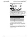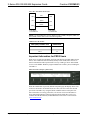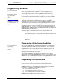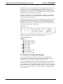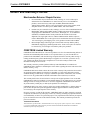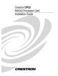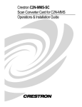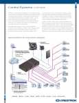
1
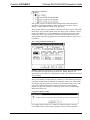
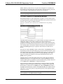
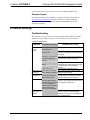
Crestron C2COM-2 & C2COM-3 2-Series RS-232/422/485 Expansion Cards Operations & Installation Guide This document was prepared and written by the Technical Documentation department at: Crestron Electronics, Inc. 15 Volvo Drive Rockleigh, NJ 07647 1-888-CRESTRON All brand names, product names and trademarks are the property of their respective owners. ©2003 Crestron Electronics, Inc. Crestron C2COM-2/3 2-Series RS-232/422/485 Expansion Cards Contents 2-Series RS-232/422/485 Expansion Cards: C2COM-2/3 1 Introduction ............................................................................................................................... 1 Functions and Features................................................................................................ 1 Specifications .............................................................................................................. 2 Physical Description.................................................................................................... 2 Industry Compliance ................................................................................................... 3 Installation and Hookup............................................................................................................. 3 Installation ................................................................................................................... 4 Hookup ........................................................................................................................ 4 Important Information for PRO2 Users....................................................................... 6 Programming Software.............................................................................................................. 7 Programming with the Crestron AppBuilder............................................................... 7 Programming with SIMPL Windows.......................................................................... 7 Problem Solving ...................................................................................................................... 11 Troubleshooting ........................................................................................................ 11 Further Inquiries........................................................................................................ 12 Future Updates .......................................................................................................... 12 Return and Warranty Policies.................................................................................................. 13 Merchandise Returns / Repair Service ...................................................................... 13 CRESTRON Limited Warranty ................................................................................ 13 Operations & Installation Guide - Doc. 8192 Contents • i Crestron C2COM-2/3 2-Series RS-232/422/485 Expansion Cards 2-Series RS-232/422/485 Expansion Cards: C2COM-2/3 Introduction Functions and Features The C2COM-2 and C2COM-3 RS-232/422/485 expansion cards provide RS-232, RS-422, or RS-485 serial communication for a Crestron® 2-Series control system (PRO2, RACK2, PAC2, or AV2 with cage card). The C2COM-2 has two serial ports while the C2COM-3 has three serial ports. The C2COM-2/3 fits in any of the 2Series control system’s Y-bus slots. The Y-bus provides high-speed communications and supports current and enhanced Crestron control system expansion cards. All C2COM-2/3 ports can communicate with the Crestron Network Poll Accelerator. NOTE: The Network Poll Accelerator allows a 2-Series control system to maintain a fast response time (high-speed communication) between the control system and a large number of Cresnet® devices. For more information, refer to the latest revision of the Network Poll Accelerator Operations Guide (Doc. 6087). The C2COM-2/3 supports baud rates up to 115,200 bps (and higher with the Network Poll Accelerator), and a variety of communication parameters with hardware and software handshaking. Valid parameters are shown in the functional summary. Functional Summary • • • • • • • Supports RS-232, RS-422, and RS-485 communications via DB9 male connector Baud rates: 300, 600, 1200, 2400, 4800, 9600, 19200, 38400, 57600 and 115200 Parity may be even, odd, none, or zero stick (parity bit always 0) Data bits may be 7 or 8 Stop bits may be 1 or 2 Both XON/XOFF software handshaking and RTS/CTS hardware handshaking are supported Break sequence can be generated under program control NOTE: Due to a non-standard pin configuration that allows the C2COM-2/3 to support RS-232, RS-422, and RS-485, Data Set Ready (DSR) and Data Terminal Ready (DTR) are not supported. Operations & Installation Guide - Doc. 8192 2-Series RS-232/422/485 Expansion Cards: C2COM-2/3 • 1 2-Series RS-232/422/485 Expansion Cards Crestron C2COM-2/3 Specifications The following table provides specifications for the C2COM-2/3. C2COM-2/3 Specifications SPECIFICATION Power Requirements RS-232/422/485 Baud Rate Output Signal Levels Handshaking 2-Series Control Systems Update File1,2 Operating Temperature and Humidity Dimensions DETAILS 3 Watts (0.125 Amp @ 24VDC) Up to 115.2K baud RS-232: ±12VDC RS-422/485: 0 to 5VDC Hardware - CTS, RTS, CTS/RTS Software - XON transmit, receive, bi-directional C2COM-2: Version 3.015.CUZ or later C2COM-3: Version 1.014.CUZ or later 41º to 104º F (5º to 40º C) 10 to 90% Relative Humidity (non-condensing) Height: 0.98 in (2.49 cm) Width: 5.00 in (12.70 cm) Depth: 6.80 in (17.28 cm) Weight: 4.50 oz (0.14 kg) 1 Crestron 2-Series control systems include the AV2 with CAGE2, PAC2, PRO2, and RACK2. 2 Filenames for 2-Series control system update files have a CUZ extension and can be obtained from the Downloads | Software Updates section of the Crestron website (www.crestron.com). Refer to note after this footnote. NOTE: Crestron software and any files on the website are for Authorized Crestron dealers and Crestron Authorized Independent Programmers (CAIP) only. New users may be required to register to obtain access to certain areas of the site (including the FTP site). Physical Description The C2COM-2/3 is a circuit board fastened to an aluminum faceplate. The card is manufactured to easily fit in an unoccupied Y-bus slot of a Crestron 2-Series control system. The faceplate on the C2COM-2 contains two identical bidirectional DB9 male connectors while the C2COM-3 contains three bidirectional DB9 male connectors. The connectors are labeled A, B and C. Refer to the following illustrations for a detailed view. C2COM-3 Faceplate C2COM-2 Faceplate 2 • 2-Series RS-232/422/485 Expansion Cards: C2COM-2/3 Operations & Installation Guide - Doc. 8192 Crestron C2COM-2/3 2-Series RS-232/422/485 Expansion Cards C2COM-3 (L) & C2COM-2 (R): Top, Side & Front View 6.59 in 6.81 in (16.73 cm) (17.30 cm) 6.59 in 6.81 in (16.73 cm) (17.30 cm) 5.00 in (12.70 cm) 5.00 in (12.70 cm) 0.98 in (2.49 cm) 0.98 in (2.49 cm) NOTE: These diagrams are for illustration purposes only and do not show the exact location of components on the circuit board. Industry Compliance As of the date of manufacture, the C2COM-2 and C2COM-3 have been tested and found to comply with specifications for CE marking and standards per EMC and Radiocommunications Compliance Labelling (N11785). NOTE: This device complies with part 15 of the FCC rules. Operation is subject to the following two conditions: (1) this device may not cause harmful interference, and (2) this device must accept any interference received, including interference that may cause undesired operation. Installation and Hookup The C2COM-2/3 cards are designed for installation into a dedicated expansion slot on a 2-Series control system. CAUTION: The C2COM-2/3 and control system contain electro-static discharge (ESD) sensitive devices. Perform the following procedure while wearing a Operations & Installation Guide - Doc. 8192 2-Series RS-232/422/485 Expansion Cards: C2COM-2/3 • 3 2-Series RS-232/422/485 Expansion Cards Crestron C2COM-2/3 grounding strap that is properly grounded and on a grounded workstation to avoid damaging the C2COM-2/3 and/or the control system. CAUTION: To prevent stripping of screw heads, threads, or mounting holes, DO NOT overtighten screws. Tighten only to the specification listed in the individual step(s). NOTE: If the C2COM-2/3 is being installed in an AV2, the optional CAGE2 must be installed before continuing below. For instructions on installing the CAGE2 into an AV2 control system, refer to the latest revision of the CAGE2 3-Card Expansion Cage for AV2 Installation Guide (Doc. 5964). Installation Follow the instructions below to install the C2COM-2/3 into a 2-Series control system. Tools/hardware required Non-standard DB9 (RS-232/422/485) cable (Refer to DB9 cable information on page 5) Phillips screwdriver Grounding strap or grounded workstation 1. Disconnect power from the control system. 2. Remove the two screws and blank faceplate from the desired slot in the control system using a Phillips screwdriver. 3. Align the C2COM-2/3 with the card guides in the open slot and slide the expansion card into the slot. 4. Firmly press both ends of the C2COM-2/3 faceplate to seat the expansion card in the control system connector. 5. Hand-tighten the thumbscrews to secure the C2COM-2/3 to the control system. 6. Connect DB cable(s). 7. Reapply power to the contol system. Hookup Non-standard DB9 connectors (two on the C2COM-2, three on the C2COM-3) provide distinct bidirectional serial ports on the C2COM-2/3. Refer to the following sample hookup illustration. NOTE: For pinout information on connection to third-party serial devices, download Crestron’s Cable Database Software. The latest version can be obtained from the Downloads | Software Updates section of the Crestron website (www.crestron.com). 4 • 2-Series RS-232/422/485 Expansion Cards: C2COM-2/3 Operations & Installation Guide - Doc. 8192 Crestron C2COM-2/3 2-Series RS-232/422/485 Expansion Cards Sample Hookup Connections for C2COM-2 (top) and C2COM-3 (bottom) Serial Device Serial Device NOTE: The pinout of each 9-pin port is non-standard. Therefore, do not use a straight-through DB9 cable. The following table contains pinout descriptions for RS-232 and RS-422. Conflicts with some equipment may occur unless the controlled devices are properly wired. Certain devices have specific voltage requirements. Therefore, do not use all nine pins in a given application. Although the possibility is remote, improper wiring may result in damage to the controlled device. Only the required pins for each communication type should be connected. Non-Standard COM Pinout (for RS-232 and RS-422 Communication) PIN DIRECTION DESCRIPTION 1* To C2COM-2/3 (RXD-) RS-422 Receive Data (Idles low) 2 3 4 5 6 7 8 9 (RXD) RS-232 Receive Data (TXD) RS-232 Transmit Data (TXD+) RS-422 Transmit Data (Idles high) RS-232 and RS-422 Signal Common (RXD+) RS-422 Receive Data (Idles high) (RTS) RS-232 Request to Send (CTS) RS-232 Clear to Send (TXD-) RS-422 Transmit Data (Idles low) To C2COM-2/3 From C2COM-2/3 From C2COM-2/3 Ground To C2COM-2/3 From C2COM-2/3 To C2COM-2/3 From C2COM-2/3 *RS-422 transmit and receive are balanced signals requiring two lines plus a ground in each direction. RXD+ and TXD+ should idle high (going low at start of data transmission). RXD- and TXD- should idle low (going high at start of data transmission). If necessary, RXD+/RXD- and TXD+/TXD- may be swapped to maintain correct signal levels. A common application is to use a three-wire null modem serial cable to communicate with a PC, as shown in the following diagram. Since the pinouts on the C2COM-2/3 are non-standard, the card should not be plugged into the PC directly. The pinout in this illustration emulates the IBM PC AT connector except for the RS422 signals on pins 1, 4, 6, and 9. Operations & Installation Guide - Doc. 8192 2-Series RS-232/422/485 Expansion Cards: C2COM-2/3 • 5 2-Series RS-232/422/485 Expansion Cards Crestron C2COM-2/3 Three-Wire Null Modem Serial Cable RED RXD 2 3 RXD WHITE TXD 3 2 TXD BLACK GND 5 5 GND 9-PIN FEMALE "D" CONNECTOR 9-PIN FEMALE "D" CONNECTOR NOTE: To support RS-485, tie pin 1 (RXD-) to pin 9 (TXD-) and pin 4 (TXD+) to pin 6 (RXD+) in the cable (refer to the following table). COM Pinout to RS-485 Bus COM (DB9) CONNECTOR RS-485 BUS Tie Pins 1 & 9 - Tie Pins 4 & 6 + Pin 5 G Important Information for PRO2 Users When power is applied to the PRO2, the front panel displays the Main Menu (shown below). The COM menu function button (directly below COM) allows the user to monitor transmission and reception traffic on every COM-type device and card that is active in the SIMPL Windows program loaded in the control system, including the C2COM-2/3. PRO2 Front Panel (Sample of Main Menu) When the COM button is pressed, (default front panel page) the display shows a list of devices and cards to be monitored (one at a time). The user selects the slot and port for the C2COM-2/3 by using the NEXT or PREV buttons on the panel. For more information on viewing port traffic, refer to latest revision of the PRO2: 2Series Integrated Dual Bus Control System Operations Guide (Doc. 5957). It is available from the Downloads | Product Manuals section of the Crestron website (www.crestron.com). 6 • 2-Series RS-232/422/485 Expansion Cards: C2COM-2/3 Operations & Installation Guide - Doc. 8192 Crestron C2COM-2/3 2-Series RS-232/422/485 Expansion Cards Programming Software Have a comment about Crestron software? Direct software related suggestions and/or complaints to Crestron via email ([email protected]). Do not forward any queries to this address. Instead refer to “Further Inquiries” on page 12 for assistance. Setup is easy thanks to Crestron’s Windows-based programming software. Crestron Application Builder™ (AppBuilder) creates a complete project, with no special programming required. Crestron AppBuilder completes all necessary programming for a base system. Once Crestron AppBuilder creates the project, the system interfaces and program logic can be customized. It can easily be modified with Crestron development tools (i.e., SIMPL Windows). The program output of Crestron AppBuilder is a SIMPL Windows program with much of the functionality encapsulated in macros. Therefore, extending the capabilities of the system is very easy. Crestron AppBuilder and SIMPL Windows are intended for users with different levels of programming knowledge. Crestron AppBuilder is easier to use for the beginning programmer, and much faster for all programmers. However, it does not allow the degree of control and flexibility that SIMPL Windows does. Of course, one can initiate programming using the easiest method (Crestron AppBuilder) and use advanced techniques that are available from SIMPL Windows to customize the job. The following are recommended software version requirements for the PC: • SIMPL Windows version 2.04.04 or later with library update file 209 (C2COM-3 only requires version 2.01.06 or later). Requires SIMPL+ Cross Compiler version 1.1. • Crestron Database 15.9.1 or later. • Application Builder 1.1.9 (1.1.9 for C2COM-2) or later. Requires SIMPL Windows. Programming with the Crestron AppBuilder The easiest method of programming, but does not offer as much flexibility as SIMPL Windows. The Crestron AppBuilder offers automatic programming for such residential and commercial applications as audio distribution, home theater, video conferencing, and lighting. The interface of this tool guides you through a few basic steps for designating rooms and specifying the control system, touchpanels, devices, and functionality. The Crestron AppBuilder then programs the system, including all touchpanel projects and control system logic. The Crestron AppBuilder is fully integrated with Crestron's suite of software development tools, including SIMPL Windows, VT Pro-e, Crestron Database, User IR Database, and User Modules Directory. The Crestron AppBuilder accesses these tools behind the scenes, enabling you to easily create robust systems. Programming with SIMPL Windows NOTE: The following assumes that the reader has knowledge of SIMPL Windows. If not, refer to the extensive help information provided with the software. NOTE: The following are acceptable file extensions for programs that include a C2COM-2/3, developed for specific control system types: .smw projectname.smw (source file) .spz projectname.spz (compiled file for 2-series) . .usp projectname.usp (source code module for SIMPL+) NOTE: In the following, the PRO2 control system is used. Operations & Installation Guide - Doc. 8192 2-Series RS-232/422/485 Expansion Cards: C2COM-2/3 • 7 2-Series RS-232/422/485 Expansion Cards Crestron C2COM-2/3 SIMPL Windows is Crestron's primary software for programming Crestron control systems. It provides a well-designed graphical environment with a number of workspaces (i.e., windows) in which a programmer can select, configure, program, test, and monitor a Crestron control system. SIMPL Windows offers drag and drop functionality in a familiar Windows environment. This section explains how to create a SIMPL Windows program that includes the C2COM-2/3. It also gives descriptions of parameters and features of the selected control and serial devices and drivers. Configuration Manager is where programmers “build” a Crestron control system by selecting hardware from the Device Library. In Configuration Manager, drag the PRO2 from the Control Systems folder of the Device Library and drop it in the upper pane of the System Views. The PRO2 with its associated communication ports is displayed in the System Views upper pane. PRO2 System View The System Views lower pane displays the PRO2 system tree. This tree can be expanded to display and configure the communications ports. Expanded PRO2 System Tree C2Y Card Slot in Configuration Manager The C2Y Card Slots 01-03 can hold a C2COM-2/3. Once a C2COM-2/3 is configured in a C2Y Card Slot, the slot allows serial communication using RS232/422/485 between a serial device and the PRO2 control system. In Configuration Manager, drag the C2COM-2/3 from the Plug-in Control Cards | Cards (2-Series Y Bus) folder of the Device Library and drop it on the C2Y Card Slot (01) in System Views. The PRO2 displays the C2COM-2/3 serial driver in slot 01. The PRO2 system tree displays the C2COM-2/3 in Slot 1. Click + to expand the tree so you can view the ports of the C2COM-2/3. Refer to following graphic that shows a C2COM-3. 8 • 2-Series RS-232/422/485 Expansion Cards: C2COM-2/3 Operations & Installation Guide - Doc. 8192 Crestron C2COM-2/3 2-Series RS-232/422/485 Expansion Cards Expanded Slot 1:C2COM-3 Each port has a built-in serial driver with communication settings that must be specified in Configuration Manager: double-click Port A to open the “Device Settings” window, and then click the Serial Settings tab. These settings define the protocol that a controlled serial device expects, and include the baud rate, parity, and the number of data bits and stop bits. In addition, a device might require hardware or software handshaking, which controls the flow of data between two devices. The exact protocol will be described in the manufacturer's documentation. The following graphic shows the default settings for each port on a C2COM-2/3. Device Settings Window/Serial Settings tab NOTE: If a different serial device to is connected to Port A, these values may need to be changed to the required settings for the device. SIMPL Windows can automatically set the values for a controlled device that is selected from the Crestron device database. The Crestron database includes numerous serial devices, with default logic and preconfigured communication settings that are compatible with the ports on the COM card. Simply drag the serial device from the Crestron Database folder to one of the ports on the COM card and click Yes when prompted (refer to the following diagram) to replace the serial driver for that port. In most cases, the default logic should be loaded as well. Configuration Manager Prompt For example, drag the Canon VC-C1 (RS-232 Control) serial driver from the Crestron DB | Canon | Camera folder, and drop it on Port A of the C2COM-2/3. Operations & Installation Guide - Doc. 8192 2-Series RS-232/422/485 Expansion Cards: C2COM-2/3 • 9 2-Series RS-232/422/485 Expansion Cards Crestron C2COM-2/3 SIMPL Windows prompts the user to replace the existing driver. Click Yes twice. Now double-click the Canon driver in the system tree. The Serial Settings tab in the “Device Settings” window displays the values for the Canon driver. NOTE: Some serial devices in the Crestron Database have the same serial driver settings as the SIMPL Windows default settings. C2COM-2/3 Symbol in Programming Manager Programming Manager is where programmers “program” a Creston control system by assigning signals to symbols. The following illustrates the symbol associated with the ports of the C2COM-3 in SIMPL Windows. Detail View of C2COM-3 Device Symbol (Port A) in SIMPL Windows' Programming Manager The [tx$] (transmit) and [rx$] (receive) signals transmit serial data to and from the COM port in whatever port or driver settings is specified for the device in Configuration Manager. The protocol that a device expects will be described in the manufacturer's documentation and includes the speed of communication (baud rate), error checking (parity), the number of data bits and stop bits, and any hardware or software handshaking that may be required to control the flow of data between devices. Some devices require a [break] to enable synchronization. The [break] input drives the transmit pin of the associated COM port low (00 Hex at half the baud rate), thus interrupting transmission of data. Some [break] signals can be 17 to 20 bits of logic low, whereas others hold transmission low for as long as [break] remains high. Again, the hardware documentation will contain information about the type of [break] a device generates. The [rts] (request to send) input and the [cts] (clear to send) output are hardware handshaking signals for use in applications where explicit handshaking control is required. These signals are enabled only when the Handshaking setting of the device is set to RTS, CTS, or RTS/CTS in Configuration Manager. Some serial driver symbols go beyond the basic serial drivers and have the added capability to function as Serial I/O symbols. That is, in addition to the signals just described, these symbols have an [enable] input, [str] and [delimiter] parameters, and digital inputs and outputs. Together with [tx$] and [rx$], these signals function identically to a Serial I/O symbol, except that the positions of the input and output signals are reversed. NOTE: Input and output lines in brackets ([ or ]) are considered optional and may not be required in every SIMPL Windows program. 10 • 2-Series RS-232/422/485 Expansion Cards: C2COM-2/3 Operations & Installation Guide - Doc. 8192 Crestron C2COM-2/3 2-Series RS-232/422/485 Expansion Cards For more information, refer to the latest release of the SIMPL Windows help. Example Program An example program for the C2COM-2/3 is available from the Crestron FTP site (ftp://ftp.crestron.com/Examples/). Search for the file C2COM-2&3.ZIP that contains the example program, associated files and a README.TXT file that describes the program. Problem Solving Troubleshooting The table below provides corrective action for possible trouble situations. If further assistance is required, please contact a Crestron customer service representative. C2COM-2/3 Toubleshooting TROUBLE C2COM-2/3 does not function. POSSIBLE CAUSE(S) Control system is not receiving power. CORRECTIVE ACTION Verify power to the control system. Circuit card is not properly Verify C2COM-2/3 is properly inserted into control system slot per procedures in seated in slot. this guide. Cable from C2COM-2/3 to Verify wiring. Connect only the required pins for each communication type. controlled equipment is incorrect. Incorrect serial port settings. Programming error. Framing Error or Cable noise* or improper Parity Error comm settings in program. Overrun Error or C2COM-3 is receiving data RX Buffer full at a higher rate than the program can process. TX Buffer Full C2COM-2/3 is sending large quantities of data in excess of the device baud rate or handshaking is enabled and the receiving end is preventing the system from transmitting. Controlled Cable/Wiring problems device does not respond Verify the communication parameters assigned in the "Device Settings" window as described in the Programming section. Check SIMPL Windows program. Verify communication settings (Serial Settings tab) and wiring. Enable hardware or software handshaking in communication settings (Serial Settings tab) and in device. Change program to reduce serial data to device or use a higher baud rate if device can support the higher rate. Confirm and/or check the cable pinouts using the Crestron Cable Database software or refer to the user manual for the controlled device. *Cable noise can be caused by high frequency interference, etc. Operations & Installation Guide - Doc. 8192 2-Series RS-232/422/485 Expansion Cards: C2COM-2/3 • 11 2-Series RS-232/422/485 Expansion Cards Crestron C2COM-2/3 Further Inquiries If after reviewing this Operations and Installation Guide, you cannot locate specific information or have questions, please take advantage of Crestron's award winning customer service team by calling: • In the US and Canada, call Crestron’s corporate headquarters at 1-888-CRESTRON [1-888-273-7876]. • In Europe, call Crestron International at +32-15-50-99-50. • In Asia, call Crestron Asia at +852-2341-2016. • In Latin America, call Crestron Latin America at +5255-5093-2160. • In Australia and New Zealand, call Creston Control Solutions at +61-2-9737-8203. Future Updates As Crestron improves functions, adds new features, and extends the capabilities of the C2COM-2/3, additional information may be made available as manual updates. These updates are solely electronic and serve as intermediary supplements prior to the release of a complete technical documentation revision. Check the Crestron website (www.crestron.com) periodically for manual update availability and its relevance. Updates are available from the Download | Product Manuals section and are identified as an “Addendum” in the Download column. 12 • 2-Series RS-232/422/485 Expansion Cards: C2COM-2/3 Operations & Installation Guide - Doc. 8192 Crestron C2COM-2/3 2-Series RS-232/422/485 Expansion Cards Return and Warranty Policies Merchandise Returns / Repair Service 1. No merchandise may be returned for credit, exchange, or service without prior authorization from CRESTRON. To obtain warranty service for CRESTRON products, contact the factory and request an RMA (Return Merchandise Authorization) number. Enclose a note specifying the nature of the problem, name and phone number of contact person, RMA number, and return address. 2. Products may be returned for credit, exchange, or service with a CRESTRON Return Merchandise Authorization (RMA) number. Authorized returns must be shipped freight prepaid to CRESTRON, 6 Volvo Drive, Rockleigh, N.J., or its authorized subsidiaries, with RMA number clearly marked on the outside of all cartons. Shipments arriving freight collect or without an RMA number shall be subject to refusal. CRESTRON reserves the right in its sole and absolute discretion to charge a 15% restocking fee, plus shipping costs, on any products returned with an RMA. 3. Return freight charges following repair of items under warranty shall be paid by CRESTRON, shipping by standard ground carrier. In the event repairs are found to be non-warranty, return freight costs shall be paid by the purchaser. CRESTRON Limited Warranty CRESTRON ELECTRONICS, Inc. warrants its products to be free from manufacturing defects in materials and workmanship under normal use for a period of three (3) years from the date of purchase from CRESTRON, with the following exceptions: disk drives and any other moving or rotating mechanical parts, pan/tilt heads and power supplies are covered for a period of one (1) year; touchscreen display and overlay components are covered for 90 days; batteries and incandescent lamps are not covered. This warranty extends to products purchased directly from CRESTRON or an authorized CRESTRON dealer. Purchasers should inquire of the dealer regarding the nature and extent of the dealer's warranty, if any. CRESTRON shall not be liable to honor the terms of this warranty if the product has been used in any application other than that for which it was intended, or if it has been subjected to misuse, accidental damage, modification, or improper installation procedures. Furthermore, this warranty does not cover any product that has had the serial number altered, defaced, or removed. This warranty shall be the sole and exclusive remedy to the original purchaser. In no event shall CRESTRON be liable for incidental or consequential damages of any kind (property or economic damages inclusive) arising from the sale or use of this equipment. CRESTRON is not liable for any claim made by a third party or made by the purchaser for a third party. CRESTRON shall, at its option, repair or replace any product found defective, without charge for parts or labor. Repaired or replaced equipment and parts supplied under this warranty shall be covered only by the unexpired portion of the warranty. Except as expressly set forth in this warranty, CRESTRON makes no other warranties, expressed or implied, nor authorizes any other party to offer any warranty, including any implied warranties of merchantability or fitness for a particular purpose. Any implied warranties that may be imposed by law are limited to the terms of this limited warranty. This warranty statement supercedes all previous warranties. Trademark Information All brand names, product names, and trademarks are the sole property of their respective owners. Windows is a registered trademark of Microsoft Corporation. Windows95/98/Me/XP and WindowsNT/2000 are trademarks of Microsoft Corporation. Operations & Installation Guide - Doc. 8192 2-Series RS-232/422/485 Expansion Cards: C2COM-2/3 • 13 2-Series RS-232/422/485 Expansion Cards Crestron C2COM-2/3 This page intentionally left blank. 14 • 2-Series RS-232/422/485 Expansion Cards: C2COM-2/3 Operations & Installation Guide - Doc. 8192 Crestron C2COM-2/3 2-Series RS-232/422/485 Expansion Cards This page intentionally left blank. Operations & Installation Guide - Doc. 8192 2-Series RS-232/422/485 Expansion Cards: C2COM-2/3 • 15 Crestron Electronics, Inc. 15 Volvo Drive Rockleigh, NJ 07647 Tel: 888.CRESTRON Fax: 201.767.7576 www.crestron.com Operations & Installation Guide – DOC. 8192 03.03 Specifications subject to change without notice.