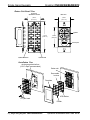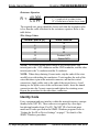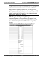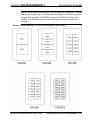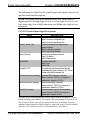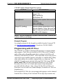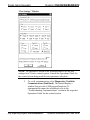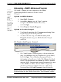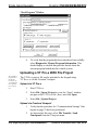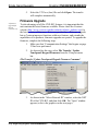
1
Crestron CNX-B2/B4/B6/B8/B12 Single Gang Keypads Operations & Installation Guide This document was prepared and written by the Technical Documentation department at: Crestron Electronics, Inc. 15 Volvo Drive Rockleigh, NJ 07647 1-888-CRESTRON All brand names, product names and trademarks are the property of their respective owners. ©2003 Crestron Electronics, Inc. Crestron CNX-B2/B4/B6/B8/B12 Single Gang Keypads Contents Single Gang Keypads: CNX-B2/B4/B6/B8/B12 1 Introduction......................................................................................1 Features and Functions ..........................................................1 Specifications.........................................................................3 Physical Description ..............................................................4 Industry Compliance..............................................................7 Setup.................................................................................................7 Network Wiring .....................................................................7 Identity Code .........................................................................8 Installation ...........................................................................12 Programming Software ..................................................................14 Programming with Crestron AppBuilder or D3 Pro ...............15 Programming with SIMPL Windows..................................15 Programming with VT Pro-e ...............................................21 Uploading and Upgrading..............................................................22 Communication Settings......................................................23 Uploading a SIMPL Windows Program..............................27 Uploading a VT Pro-e WAV File Project ...........................28 Firmware Upgrade ...............................................................30 Serial Number Assignment..................................................32 Problem Solving.............................................................................33 Troubleshooting...................................................................33 Further Inquiries ..................................................................34 Future Updates.....................................................................34 Software License Agreement.........................................................35 Return and Warranty Policies ........................................................37 Merchandise Returns / Repair Service .......................37 CRESTRON Limited Warranty ...................................37 Operations & Installation Guide - DOC. 8173A Contents • i Crestron CNX-B2/B4/B6/B8/B12 Single Gang Keypads Single Gang Keypads: CNX-B2/B4/B6/B8/B12 Introduction Features and Functions The CNX-B2/B4/B6/B8/B12-series Single Gang Keypads are wallmounted user interfaces that can be part of a Crestron solution total control system. The keypads are standard Cresnet® devices, and provide fingertip control when the control system is properly programmed using SIMPL Windows. The number in the product’s name corresponds to the number of buttons on the panel. Each of these panels is available in three colors: almond, black, and white. A letter at the end of the product name, ‘A’, ‘B’, or ‘W’, denotes the color; i.e., CNX-B12B is a black 12-button unit. For simplicity within this guide, the letter designating color is omitted. Furthermore, even though the CNX-B12 is featured in descriptions and illustrations throughout this guide, the information herein applies to the other keypads as well. Exceptions are noted. NOTE: Keypads can also be mounted in groups. For more information, refer to the latest version of the B-G2-FP and B-G3-FP, Double and Triple Gang Keypads (Doc. 8182). Functional Summary • Ergonomic buttons are easy to read from any angle • Backlit buttons are easy to locate • LED indicators provide visual feedback of commands • A speaker provides audio feedback of WAV files • A temperature sensor reports to Cresnet for environment monitoring Operations & Installation Guide - DOC. 8173A Single Gang Keypads: CNX-B2/B4/B6/B8/B12 • 1 Single Gang Keypads Crestron CNX-B2/B4/B6/B8/B12 The keypads feature backlit-capable ergonomic buttons and are designed for wall mounting in a standard single-gang electrical box. The keypad’s colors and finishes can be used to accent a home’s colors, wall coverings, or décor. NOTE: The CNX-B12 keypad is supplied with 12 blank pushbuttons. As an option, custom-engraved keys can be designed and obtained by using the Crestron Engraver software. Version 2.0.1.5 or later is available from the Downloads | Software Updates section of the Crestron website (www.crestron.com). NOTE: Designer series faceplates are also available for customized single-, double-, and triple-gang configurations. Contact a Crestron customer service representative for details. NOTE: Temperature reading accuracy is affected by unit indicators and backlight state. All buttons on the keypad are functionally identical and have associated light emitting diodes (LEDs) that serve as user feedback indicators. Each LED’s illumination is independently addressable, and is programmable using SIMPL Windows. The keypad also contains a temperature sensor that reports to the Cresnet control system, and an audio speaker that can provide audio feedback via WAV sound files. In the program, the backlight and button LED intensity levels can be set from 0 to 100%. Similarly, the speaker volume level can be set from 0 to 100%. Refer to “CNX-B12 Symbol in Programming Manager” on page 18 for details. Refer also to the note concerning temperature sensor accuracy and LED settings on page 13. 2 • Single Gang Keypads: CNX-B2/B4/B6/B8/B12 Operations & Installation Guide - DOC. 8173A Crestron CNX-B2/B4/B6/B8/B12 Single Gang Keypads Specifications The following table provides specifications for the keypads. Specifications for the Keypads SPECIFICATION Power Requirements Default Network ID Temperature Sensor Type Precision Accuracy Range LED Type Backlight Type Wave File Format/Size Limit DETAILS 3 Watts (0.125 Amp @ 24 VDC) 60 Source File Format Compiled File Format Control System Update Files4, 5, 6 2-Series Control System Update CEN/CN-TVAV Update File CNMSX-AV/Pro Update File CNRACKX/-DP Update File ST-CP Update File Dimensions and Weight Environmental Temperature Linear, digital 0.18°F (0.1°C) 1.8°F (1.0°C)1 32°F - 113°F (0°C - 45°C)2 Red, dimmable via program White, dimmable via program 8-bit, 8Khz, PCM/512K total capacity, max. of 101 WAV files3 projectname. vtp projectname. hex Version C2-1001.CUZ or later Version 5.10.13V.UPZ or later Version 5.10.11X.UPZ or later Version 5.10.11W.UPZ or later Version 4.02.04S.UPZ or later Height: 4.76 in (12.1 cm) Width: 2.91 in (5.57 cm) Depth: 1.54 in (3.90 cm)7 Weight: 2.60 oz (75 g) 32°F - 113°F (0°C - 45°C) 1. Temperature accuracy with backlight and indicator LEDs off. 2. Sensor reads temperature in degrees Centigrade; keypad firmware converts reading to Fahrenheit. 3. The button panel can store up to 101 wav files that produce a total maximum of approximately 60 seconds playback. Operations & Installation Guide - DOC. 8173A Single Gang Keypads: CNX-B2/B4/B6/B8/B12 • 3 Single Gang Keypads Crestron CNX-B2/B4/B6/B8/B12 4. The latest software versions can be obtained from the Downloads | Software Updates section of the Crestron website (www.crestron.com). Refer to the NOTE following these footnotes. 5. Crestron 2-Series control systems include the AV2, CP2/CP2E, MP2/MP2E, PAC2, PRO2 and RACK2. 6. CNX update files are required for either CNMSX-AV/Pro or CNRACKX/-DP. Filenames for CNX update files have a UPZ extension, and ST-CP files are in one EXE or zipped UPZ file. To avoid program problems, make sure you are using the update file with the correct suffix letter (e.g., S, V, W, X). 7. The depth of the Keypad is listed without the Cresnet connector (approximately 0.45 in) plus clearance for the wiring. NOTE: Crestron software and any files on the website are for Authorized Crestron dealers and Crestron Authorized Independent Programmers (CAIP) only. New users may be required to register to obtain access to certain areas of the site (including the FTP site). Physical Description Refer to the figures on pages 5 and 6. The number of buttons on a keypad can be 2, 4, 6, 8, or 12. They are arranged numerically from left to right, top to bottom and each has an associated LED window. NOTE: The Keypad Physical Views illustrations show examples of 12button and 8-button keypads; other models have different configurations. Refer to the button arrangement illustration on page 19. The removable faceplate and divider attach to the button unit once it is mounted. Each keypad has a button unit with a membrane switch, a rear speaker, and a male Cresnet network port labeled 24 Y Z G. The port provides for operating power and for communications to/from the keypad. 4 • Single Gang Keypads: CNX-B2/B4/B6/B8/B12 Operations & Installation Guide - DOC. 8173A Crestron CNX-B2/B4/B6/B8/B12 Single Gang Keypads Keypad Physical Views 12-button Model (White Color) 8-button Model (Black Color) Keypad Overall Dimensions Side View Front View 1.536 in (3.902 cm) 2.912 in (5.568 cm) 1 2 4.762 in (12.096 cm) 12 Buttons 1-12 LED window 1.067 in (2.710 cm) NOTE: Illustration is for 12-button keypad, other models have fewer buttons. Button numbers are for programming purposes only. Refer to the illustrations on page 19 for more button arrangement details. Operations & Installation Guide - DOC. 8173A Single Gang Keypads: CNX-B2/B4/B6/B8/B12 • 5 Single Gang Keypads Crestron CNX-B2/B4/B6/B8/B12 Button Unit Detail View Front View with buttons removed Back View 1.788 in (4.541 cm) 1.696 in (4.301 cm) TOP Speaker 4.158 in (10.56 cm) 2.696 in (6.848 cm) NET Cresnet port 24 Y Z G Rubber Membrane Indicator LED Installation View Single gang electrical box (2.5 in. depth recommended) Button unit Removable buttons Faceplate 1 in. pan head LED window Divider 6 • Single Gang Keypads: CNX-B2/B4/B6/B8/B12 Operations & Installation Guide - DOC. 8173A Crestron CNX-B2/B4/B6/B8/B12 Single Gang Keypads Industry Compliance As of the date of manufacture, the keypads have been tested and found to comply with specifications for CE marking and standards per EMC and Radiocommunications Compliance Labelling (N11785). NOTE: This device complies with part 15 of the FCC rules. Operation is subject to the following two conditions: (1) this device may not cause harmful interference, and (2) this device must accept any interference received, including interference that may cause undesired operation. Setup Network Wiring CAUTION: Use only Crestron power supplies for Crestron equipment. Failure to do so could cause equipment damage or void the Crestron warranty. NOTE: When installing network wiring, refer to the latest revision of the wiring diagram(s) appropriate for your specific system configuration, available from the Downloads | Product Manuals | Software and Wiring Diagrams section of the Crestron website (www.crestron.com). When calculating the wire gauge for a particular Cresnet run, the length of the run and the power factor of each network unit to be connected must be taken into consideration. If Cresnet units are to be daisy-chained on the run, the power factor of each unit to be daisy-chained must be added together to determine the power factor of the entire chain. If the unit is a home-run from a Crestron system power supply network port, the power factor of that unit is the power factor of the entire run. The length of the run in feet and the power factor of the run should be used in the resistance equation on the next page to calculate the value on the right side of the equation. Operations & Installation Guide - DOC. 8173A Single Gang Keypads: CNX-B2/B4/B6/B8/B12 • 7 Single Gang Keypads Crestron CNX-B2/B4/B6/B8/B12 Resistance Equation R < 40,000 L x PF Where: R = Resistance (refer to table below). L = Length of run (or chain) in feet. PF = Power factor of entire run (or chain). The required wire gauge should be chosen such that the resistance value is less than the value calculated in the resistance equation. Refer to the table below. Wire Gauge Values RESISTANCE (R) WIRE GAUGE 4 16 6 18 10 20 15 22 13 Doubled CAT5 8.7 Tripled CAT5 NOTE: All Cresnet wiring must consist of two twisted pairs. One twisted pair is the +24V conductor and the GND conductor, and the other twisted pair is the Y conductor and the Z conductor. NOTE: When daisy-chaining Cresnet units, strip the ends of the wires carefully to avoid nicking the conductors. Twist together the ends of the wires that share a pin on the network connector, and tin the twisted connection. Apply solder only to the ends of the twisted wires. Avoid tinning too far up the wires or the end becomes brittle. Insert the tinned connection into the Cresnet connector and tighten the retaining screw. Repeat the procedure for the other three conductors. Identity Code Every equipment and user interface within the network requires a unique identity code (NET ID). These codes are recognized by a two-digit hexadecimal number from 03 to FE. The NET ID of each unit must match an ID code specified in the SIMPL Windows program. Refer to “Setting the Net ID in Device Settings” on page 17 for details of the SIMPL Windows procedure. 8 • Single Gang Keypads: CNX-B2/B4/B6/B8/B12 Operations & Installation Guide - DOC. 8173A Crestron CNX-B2/B4/B6/B8/B12 Refer to the note on page 22 for a definition of Viewport. Single Gang Keypads The NET ID of the keypad has been factory set to 60. The NET IDs of multiple keypads in the same system must be unique. NET IDs are changed from a personal computer (PC) via the Crestron Viewport. NOTE: For detailed information on establishing communication between the PC and control system, refer to “Communication Settings” on page 23. If communication cannot be established, refer to the “Troubleshooting Communications” section in the respective Operations Guide for the control system. There are two different methods—Method A or Method B—for setting the keypad NET IDs: Method A (Cresnet address-settable ID), described below, must be used for keypads with firmware prior to version 1.06, but can be used with later versions of firmware and requires that a single keypad be the only network device connected to the control system. Method B (Touch Settable IDs), which begins on page 10, applies to keypads with firmware version 1.06 or later, in a Cresnet system with 2-Series control system upgrade file (CUZ) version 3.008 or later. These upgrades enable Touch Settable ID (TSID) functionality, which makes it possible for the control system to recognize a network device via its serial number, which is stored in the device’s memory. This method does not require that any devices be disconnected from the network; NET IDs may be set with the entire Cresnet system intact. However, the serial number must have been entered when the firmware was upgraded to version 1.06, either at the factory or in the field. Use the appropriate method to set the keypad NET ID. Method A (Cresnet address-settable ID) 1. Ensure that the keypad is the only device connected to the control system. 2. Open the Crestron Viewport. 3. From the Viewport menu, select Functions | Set Network ID. The software checks the baud rate and then opens the "Set Network ID" window. 4. In the "Set Network ID" window, select the CNX-B12 from the Current Network Devices text window. Operations & Installation Guide - DOC. 8173A Single Gang Keypads: CNX-B2/B4/B6/B8/B12 • 9 Single Gang Keypads Crestron CNX-B2/B4/B6/B8/B12 5. Select the new NET ID for the keypad from the Choose the new network ID for the selected device (Hex): text box. 6. Click Set ID to initiate the change. This will display the "ID command has been sent" window. 7. In the "Command Complete" window, click OK. 8. In the Current Network Devices text window, verify the new NET ID code. 9. In the "Set Network ID" window, click Close. NOTE: The new NET ID code may also be verified by selecting Diagnostic | Report Network Devices in the Viewport (alternately, select F4). 10. Repeat this procedure for each keypad to be added to the system. Method B (Touch Settable IDs) Before using this method, you should have a list of all current network devices and their Net IDs, to avoid assigning duplicate IDs. Set Net ID via D3 Pro Version 1.0 of this program includes procedures that enable setting the Net ID by touching any button of a set of keypads. Refer to the extensive help information provided with the software file for instructions. Set Net ID by TSID These procedures are for TSID-enabled network devices during the initial configuration of a Cresnet system or when such devices are being added/replaced. 1. Ensure that all keypads are connected to the control system. 2. Open the Crestron Viewport version 3.35 or later. 3. From the Viewport menu, select Functions | Assign Cresnet ID by Serial Number. The “Set Net ID by TSID” window appears. The window is first displayed with the data fields empty. • When you click on the Search for Touch Settable Devices button, the system searches the network and lists 10 • Single Gang Keypads: CNX-B2/B4/B6/B8/B12 Operations & Installation Guide - DOC. 8173A Crestron CNX-B2/B4/B6/B8/B12 Single Gang Keypads all TSID-enabled devices found, as shown in the figure below. • This information is similar to the report produced by pressing F4 (Report Network Devices); the first eight digits of each line constitute the TSID number (hexadecimal form of the serial number). Set Net ID by TSID Window Serial Number to TSID Conversion If you know the device serial number, but not its TSID number, or you know the TSID but not the serial number, do the following: 1. Open the Crestron Viewport. 2. From the Viewport menu, select Functions | Serial Number ÅÆ TSID Conversion Tool. The “Serial Number ÅÆTSID Conversion Tool” window is displayed. Operations & Installation Guide - DOC. 8173A Single Gang Keypads: CNX-B2/B4/B6/B8/B12 • 11 Single Gang Keypads Crestron CNX-B2/B4/B6/B8/B12 Serial Number to TSID Conversion Tool Window 3. Enter the serial number or TSID number as instructed; press the appropriate button to obtain the corresponding number. Installation The following tools/hardware are required for installation: • Cresnet network cable (not supplied) • Phillips screwdriver (not supplied) • Two 1 in. pan head Phillips screws (supplied) • Insulation (not supplied) NOTE: The insulation will protect the sensor from any in-wall conditions (such as drafts, etc.). Use type in compliance with local codes. After the Cresnet network wiring has been installed and verified, use the following procedure to install the keypad in a standard, single-gang electrical box (refer to illustrations on pages 5 and 6). 1. Turn Cresnet system power OFF. 2. Connect the Cresnet cable with supplied mate to the keypad’s Cresnet port and the other end to the control system. 3. Insert insulation in electrical box (make sure it fills void of box not occupied by keypad). 12 • Single Gang Keypads: CNX-B2/B4/B6/B8/B12 Operations & Installation Guide - DOC. 8173A Crestron CNX-B2/B4/B6/B8/B12 Single Gang Keypads CAUTION: Excess wire pinched between the keypad and electrical box could short out. Make sure that all excess wire is completely inside the electrical box and not between the box and the keypad. 4. 5. Make sure button unit is oriented as marked with arrow at top, and place it in the electrical box. Attach button unit using the supplied 1 in. pan head screws. 6. Attach buttons with LED window oriented upward to match each LED indicator. 7. Attach divider and faceplate (orient with arrow up). Make sure faceplate snaps in position. 8. Turn Cresnet system power ON. NOTE: The heat from the button LEDs can affect the reading of the temperature sensor. Thus, the accuracy of the sensor depends on the installation, and the number and intensity of LEDs that are on at a given time. If the unit is operated for about an hour with the typical number of LEDs lit and the backlight feature off, a constant offset can be determined and added to the SIMPL program to compensate for this effect, allowing you to calibrate the accuracy of the sensor to within about 3.6°F (2° C). You can also compensate for heat from the backlight, but this may result in a larger inaccuracy after a change in backlight state until the unit reaches a steady-state temperature. Operations & Installation Guide - DOC. 8173A Single Gang Keypads: CNX-B2/B4/B6/B8/B12 • 13 Single Gang Keypads Crestron CNX-B2/B4/B6/B8/B12 Programming Software Have a comment about Crestron software? Direct software related suggestions and/or complaints to Crestron via email (software@ crestron.com). Do not forward any queries to this address. Instead refer to “Further Inquiries” on page 34 for assistance. Setup is easy thanks to Crestron’s Windows-based programming software. The Crestron Application Builder™ (Appbuilder) creates a complete project, with no special programming required. Crestron Appbuilder completes all necessary programming for a base system including all touchpanel screens and the control system program. Once Crestron Appbuilder creates the project, the system interfaces and program logic can be customized. It can easily be modified with Crestron development tools (i.e., SIMPL Windows and Crestron Vision Tools® Pro-e (VT Pro-e) software packages). The program output of Crestron Appbuilder is a SIMPL Windows program with much of the functionality encapsulated in macros and templates. Therefore, extending the capabilities of the system is very easy. Crestron AppBuilder and SIMPL Windows are intended for users with different levels of programming knowledge. Crestron AppBuilder is easier to use for the beginning programmer, and much faster for all programmers. However, it does not allow the degree of control and flexibility that SIMPL Windows does. Of course, one can initiate programming using the easiest method (Crestron AppBuilder) and use advanced techniques that are available from SIMPL Windows to customize the job. Crestron Appbuilder comes with templates for all supported interfaces. If a user wishes to create a touchpanel project using templates with a different look-and-feel, this can be accomplished by making a custom template. This custom template can then be used by Crestron Appbuilder to create the final project files to be loaded into the panels. Alternatively, VT Pro-e can be used to tweak projects created with the Crestron AppBuilder or develop original touchpanel screen designs. NOTE: Crestron recommends that you use the latest software to take advantage of the most recently released features. The latest software is available from the Downloads | Software Updates section of the Crestron website (www.crestron.com). NOTE: You can also use VT Pro-e to create WAV file programs (for sound) in the keypads. 14 • Single Gang Keypads: CNX-B2/B4/B6/B8/B12 Operations & Installation Guide - DOC. 8173A Crestron CNX-B2/B4/B6/B8/B12 Single Gang Keypads The following are the earliest useable software version requirements for the PC: • (Optional) Application Builder version 1.0.17 or later. Requires SIMPL Windows. • (Optional) D3 Pro version 1.0 or later. • SIMPL Windows version 2.01.05 or later. Requires SIMPL+® Cross Compiler version 1.1. • VT Pro-e version 2.4 or later. • Crestron Database version 15.7.2 or later. • (Optional) Crestron Engraver version 2.0.1.5 or later. Programming with Crestron AppBuilder or D3 Pro The easiest method of programming, but does not offer as much flexibility as SIMPL Windows. Crestron AppBuilder offers automatic programming for such residential and commercial applications as audio distribution, home theater, video conferencing, and lighting. The interface of this tool guides you through a few basic steps for designating rooms and specifying the control system, touchpanels, devices, and functionality. Crestron AppBuilder then programs the system, including all touchpanel projects and control system logic. Crestron D3 Pro similarly offers automatic programming for lighting, HVAC, and security. Both Crestron AppBuilder and D3 Pro are fully integrated with Crestron's suite of software development tools, including SIMPL Windows, VT Pro-e, and the Crestron Database. Both access these tools behind the scenes, enabling you to easily create robust systems. Programming with SIMPL Windows NOTE: The following assumes that the reader has knowledge of SIMPL Windows. If not, refer to the extensive help information provided with the software. NOTE: In the following description, the PRO2 control system is used. SIMPL Windows is Crestron's software for programming Crestron control systems. It provides a well-designed graphical environment with Operations & Installation Guide - DOC. 8173A Single Gang Keypads: CNX-B2/B4/B6/B8/B12 • 15 Single Gang Keypads Crestron CNX-B2/B4/B6/B8/B12 a number of workspaces (i.e., windows) in which a programmer can select, configure, program, test, and monitor a Crestron control system. SIMPL Windows offers drag and drop functionality in a familiar Windows environment. This section explains how to create a SIMPL Windows program that includes a single gang keypad. Configuration Manager is where programmers “build” a Crestron control system by selecting hardware from the Device Library. In Configuration Manager, drag the PRO2 from the Control Systems folder of the Device Library and drop it in the upper pane of the System Views. The PRO2 with its associated communication ports is displayed in the System Views upper pane. PRO2 System View The System Views lower pane displays the PRO2 system tree. This tree can be expanded to display and configure the communications ports. Expanded PRO2 System Tree C2Net-Device Slot in Configuration Manager To incorporate a CNX-B12 into the system, drag the CNX-B12 from the Wired Keypad folder of the Device Library and drop it in System Views. The PRO2 system tree displays the CNX-B12 in Slot 9, with a default NET ID of 60 as shown in the illustration on the next page. 16 • Single Gang Keypads: CNX-B2/B4/B6/B8/B12 Operations & Installation Guide - DOC. 8173A Crestron CNX-B2/B4/B6/B8/B12 Single Gang Keypads NOTE: The first CNX-B12 in a system is preset with a NET ID of 60 when its symbol is dragged into the upper pane of System Views. Additional units are assigned different NET ID numbers as they are added. C2Net Device, Slot 9 Setting the Net ID in Device Settings Double-click the CNX-B12 icon in the upper pane to open the “Device Settings” window. This window displays CNX-B12 device information. The NET ID can be changed in this window using the NET ID tab, as shown in the following figure. CNX-B12 Device Settings Window Operations & Installation Guide - DOC. 8173A Single Gang Keypads: CNX-B2/B4/B6/B8/B12 • 17 Single Gang Keypads Crestron CNX-B2/B4/B6/B8/B12 NOTE: This procedure sets the NET ID for the CNX-B12 in the program only. It does not automatically set the NET ID for the keypad itself. SIMPL Windows automatically changes NET ID values of a device added to a program if a duplicate device or a device with the same NET ID already exists in the program. Always ensure that the hardware and software settings of the NET ID match. For NET ID hardware setting details, refer to “Identity Code” on page 8. CNX-B12 Symbol in Programming Manager Programming Manager is where programmers “program” a Creston control system by assigning signals to symbols. The following graphic shows the CNX-B12 symbol in the SIMPL Windows Programming Manager. CNX-B12 symbol in SIMPL Windows Programming Manager 18 • Single Gang Keypads: CNX-B2/B4/B6/B8/B12 Operations & Installation Guide - DOC. 8173A Crestron CNX-B2/B4/B6/B8/B12 Single Gang Keypads NOTE: In the symbol, the number of press and fbck (feedback)—outputs and inputs, respectively—correspond to the number of buttons in a given keypad. For example, a CNX-B8 has press1-8 and fbck1-8 only in its symbol. The illustration below shows the button arrangement for the keypads Button Arrangement of CNX-B Series Keypads (Front Views) Operations & Installation Guide - DOC. 8173A Single Gang Keypads: CNX-B2/B4/B6/B8/B12 • 19 Single Gang Keypads Crestron CNX-B2/B4/B6/B8/B12 The following two tables list the symbol inputs and outputs, respectively, and their functional descriptions. NOTE: All signals listed in the tables are DIGITAL unless noted. A digital signal can be high (logic level of 1) or low (logic level of 0), and have rising edge (low to high) transitions, and falling edge (high to low) transitions. CNX-B12 Symbol Input Signal Descriptions INPUT fbck1 thru fbck12 DESCRIPTION Activates feedback LEDs 1-12. High/1=function feedback On Low/0=function feedback Off Enable_Temp_Rpt Enables temperature reporting to control system. High/1=reporting enable Low/0=reporting disable Temp_Format Controls temperature format. High/1=Celsius Low/0=Fahrenheit BackliteON Activates backlight. High/1=On Low/0=Off Sound20-120* Activates sound file specified by the corresponding join number in VT Pro-e. Rising edge starts sound file. IndicatorIntensity (analog) Controls LED indicator intensity. Ramp Level=0-100% (If no signal is connected, default is 100%.) BackliteIntensity (analog) Controls backlight intensity. Ramp Level=0-100% (If no signal is connected, default is 100%.) AudioVol (analog) Controls audio volume thru speaker. Ramp Level=0-100% (If no signal is connected, default is 0%.) *Sound20 is the sound assignment to join20. Sounds must be assigned in VT Pro-e and the resulting project loaded. The compiled file incorporating all relevant WAV files is xxx.hex. Refer to the VT Pro-e help file for more information. To create additional sound symbols in SIMPL Windows, right click on the CNX-B12 symbol and select Insert Symbol/Parameter Field (alternatively, select Alt +). 20 • Single Gang Keypads: CNX-B2/B4/B6/B8/B12 Operations & Installation Guide - DOC. 8173A Crestron CNX-B2/B4/B6/B8/B12 Single Gang Keypads CNX-B12 Symbol Output Signal Descriptions OUTPUT DESCRIPTION press1 thru press12 Notifies control system of button press (1-12). High/1=press On Low/0=press Off PlayingSound Notifies control system that sound file is playing. High/1=playing Low/0=not playing Temp(x10) (analog) Reports ambient temperature every 2 seconds (Enable_Temp_Rpt must be High/1). Units are tenths of a degree, e.g. 685 is 68.5 degrees. NOTE: The join assignments for panels with fewer than 12 buttons and feedback LEDs do not change. Example Program An example program for the keypad is available from the Crestron FTP site (ftp://ftp.crestron.com/Examples). Search for CNX-B12.SMW. Programming with VT Pro-e The CNX-B12 is capable of playing audio messages as system prompts and responses. These files are recorded as WAV files on a PC using an audio utility such as Sound Recorder that is packaged with Microsoft Windows 95/98/Me/XP/NT/2000™. Files from other sources may also be converted to an acceptable format by using this or a similar utility. Many other audio utilities are available commercially or as shareware. The CNX-B12 keypad accepts only the following WAV file format: PCM, 8KHz, mono, 8 bit. For more information about how to use Sound Recorder, refer to its User’s Guide and extensive help information provided with the software. Also, refer to the help file in VT Pro-e to learn how to use its audio tool, Sound Manager, to attach WAV files to a keypad project. Pre-recorded WAV files for voice prompts and responses can be obtained from the Wave Library of the Crestron FTP site (ftp://ftp.crestron.com). Operations & Installation Guide - DOC. 8173A Single Gang Keypads: CNX-B2/B4/B6/B8/B12 • 21 Single Gang Keypads Crestron CNX-B2/B4/B6/B8/B12 These files can be stored into and programmed for use in the keypad directly or may be edited with the Sound Recorder. For example, the individual files can be combined to create custom messages. To play WAV files, a CNX-B12 project must be created in VT Pro-e (with the WAV files and correct join numbers as part of the project). NOTE: If you need to create WAV files, refer to Windows Help (Using Sound Recorder). NOTE: The following are acceptable file extensions for WAV file programs developed for the keypads: .vtp projectname.vtp (source file) .hex projectname.hex (compiled file) NOTE: Join numbers assigned to a WAV file in VT Pro-e begin at 20 because join numbers below 20 are already assigned to other keypad buttons or functions. NOTE: When you begin to create a new keypad program, note that you cannot assign pages or sub pages (because keypads have no screen). Instead, use Tools | Sound Manager from the VT Pro-e menu bar to create the program and assign joins to the WAV files, etc. Once the project is created, use File | Upload Project from the VT Pro-e main menu to load it in the CNX-B12. For more information, refer to the VT Pro-e help file. NOTE: This can be done after an identity code (NET ID) is assigned to the keypad (page 8) or after installation (page 12). Uploading and Upgrading Assuming a PC is properly connected to the entire system, Crestron programming software allows the programmer to upload programs and projects to the system and touchpanel and/or keypads after their development. However, there are times when the files for the program and projects are compiled and not uploaded. Instead, compiled files may be distributed from programmers to installers, from Crestron to dealers, etc. Even firmware upgrades are available from the Crestron website as 22 • Single Gang Keypads: CNX-B2/B4/B6/B8/B12 Operations & Installation Guide - DOC. 8173A Crestron CNX-B2/B4/B6/B8/B12 Single Gang Keypads new features are developed after product releases. In those instances, one has the option to upload via the programming software or to upload and upgrade via the Crestron Viewport. NOTE: The Crestron Viewport is available as a pull-down command from SIMPL Windows and VT Pro-e (Tools | Viewport), or as a standalone utility. The Viewport utility accomplishes multiple system tasks, primarily via an RS-232 or TCP/IP connection between the control system and a PC. It is used to observe system processes, upload new operating systems and firmware, change system and network parameters, and communicate with network device consoles and touchpanels, among many other tasks. Viewport can also function as a terminal emulator for generic file transfer. All of these functions are accessed through the commands and options in the Viewport menus. Therefore, for its effectiveness as a support and diagnostic tool, the Crestron Viewport may be preferred over development tools when uploading programs and projects. The following sections define how one would upload a SIMPL Windows program or a VT Pro-e project, or upgrade the firmware of the CNX-B12. However, before attempting to upload or upgrade, it is necessary to establish communications. Communication Settings NOTE: For laptops and other PCs without a built-in RS-232 port, Crestron recommends the use of PCMCIA cards, rather than USB-toserial adapters. If a USB-to-serial adapter must be used, Crestron has tested the following devices with good results: Belkin (large model) F5U103 I/O Gear GUC232A Keyspan USA-19QW Other models, even from the same manufacturer, may not yield the same results. The procedure in this section provides details for RS-232 communication between the PC and the control system. If TCP/IP communication is preferred, consult the latest version of the Crestron e-Control Reference Operations & Installation Guide - DOC. 8173A Single Gang Keypads: CNX-B2/B4/B6/B8/B12 • 23 Single Gang Keypads Crestron CNX-B2/B4/B6/B8/B12 Guide (Doc. 6052) or the respective Operations Guide for the control system. These documents are available from the Downloads | Product Manuals section of the Crestron website (www.crestron.com). Refer to the figure below for a typical connection diagram when uploading files. Note: Use a standard DB9 male to female “straight-through” cable. Typical Connection Diagram when Uploading 1. Start SIMPL Windows. 2. From the menu bar, select Tools | Viewport to open the Crestron Viewport. 3. Refer to the figure after this step. From the Viewport menu, select Setup | Communications settings (alternatively, press Alt+D) to open the “Port Settings” window. 24 • Single Gang Keypads: CNX-B2/B4/B6/B8/B12 Operations & Installation Guide - DOC. 8173A Crestron CNX-B2/B4/B6/B8/B12 Single Gang Keypads Setup | Communications Settings Command 4. Select RS-232 as the connection type. Verify that an available COM port (COM 1 is shown after this step) is selected, and that all communication parameters and necessary options from the “Port Settings” window are selected as shown after this step. Click the OK button to save the settings and close the window. Operations & Installation Guide - DOC. 8173A Single Gang Keypads: CNX-B2/B4/B6/B8/B12 • 25 Single Gang Keypads Crestron CNX-B2/B4/B6/B8/B12 “Port Settings” Window NOTE: The parameters shown in the illustration above are the port settings for a 2-Series control system. Consult the Operations Guide for the control system being used for exact parameter selection. 5. To verify communication, select Diagnostics | Establish Communications (Find Rack). This should display a window that gives the COM port and baud rate. If communication cannot be established, refer to the “Troubleshooting Communications” section in the respective Operations Guide for the control system. 26 • Single Gang Keypads: CNX-B2/B4/B6/B8/B12 Operations & Installation Guide - DOC. 8173A Crestron CNX-B2/B4/B6/B8/B12 Single Gang Keypads Uploading a SIMPL Windows Program . A control system source file has the extension .smw. A compiled SIMPL Windows file has the extension .spz for a 2-Series control system, .bin for CNX generation, and .csz for CNX generation with SIMPL+. The SIMPL Windows file can be uploaded to the control system using SIMPL Windows or via the Crestron Viewport. Upload via SIMPL Windows 1. Start SIMPL Windows. 2. Select File | Open to view the “Open” window, navigate to the SIMPL Window file (.smw), and click Open. 3. Select Project | Transfer Program. Upload via Crestron Viewport 1. Verify that the procedure for “Communication Settings” that begins on page 23 has been performed. 2. As shown after this step, select File Transfer | Send Program (alternatively, press Alt+P) from the Viewport menu bar. File Transfer | Send Program Command 3. The “Send Program” window appears, as shown on the next page. Click Browse, locate the compiled file (.spz for PRO2) and click Open. This will display the program's header information and enable one or both of the What to Send check boxes. If the program does not contain any SIMPL+ modules, only the SIMPL Program check box will be enabled. If it does contain SIMPL+ modules, then the SIMPL+ Program(s) check box will also be enabled. Select one or both check boxes and then click Send Program to begin the transfer. NOTE: Refer to the respective Operations Guide for the control system for details about the other fields shown on the “Send Program” window. Operations & Installation Guide - DOC. 8173A Single Gang Keypads: CNX-B2/B4/B6/B8/B12 • 27 Single Gang Keypads Crestron CNX-B2/B4/B6/B8/B12 “Send Program” Window 4. To verify that the program has been transferred successfully, select Diagnostics | Report Program Information. This should display a window that provides details about the current program loaded into the control system. Uploading a VT Pro-e WAV File Project The CNX-B12 keypad source file has the extension .vtp. A compiled VT Pro-e file has the extension hex. The VT Pro-e project file can be uploaded to the keypad using VT Pro-e or via the Crestron Viewport. Upload via VT Pro-e 1. Start VT Pro-e. 2. Select File | Open | Project to view the “Open” window, navigate to the VT Pro-e file (.hex), and click Open. 3. Select File | Upload Project. Upload via Crestron Viewport 1. Verify that the procedure for “Communication Settings” that begins on page 23 has been performed. 2. As shown after this step, select File Transfer | Send Touchpanel from the Viewport menu. 28 • Single Gang Keypads: CNX-B2/B4/B6/B8/B12 Operations & Installation Guide - DOC. 8173A Crestron CNX-B2/B4/B6/B8/B12 Single Gang Keypads File Transfer | Send Touchpanel Command 3. As shown after this step, select the NET ID of the CNX-B12 keypad and then click OK. The “Open” window appears (refer to graphic below). “Select Network ID” Window NOTE: When transferring any Cresnet file (keypad project/firmware), lower the port speed baud rate to 38400 to match the Cresnet bus speed. “Open” Window Operations & Installation Guide - DOC. 8173A Single Gang Keypads: CNX-B2/B4/B6/B8/B12 • 29 Single Gang Keypads 5. Crestron CNX-B2/B4/B6/B8/B12 Select the VT Pro-e (hex) file and click Open. The transfer will complete automatically. Firmware Upgrade A firmware upgrade file has the extension .csf. To take advantage of all the CNX-B12 features, it is important that the unit contains the latest firmware available. Please check the Crestron website (http://www.crestron.com/downloads/software_updates.asp) for the latest version of firmware. Not every product has a firmware upgrade, but as Crestron improves functions, adds new features, and extends the capabilities of its products, firmware upgrades are posted. To upgrade the firmware, complete the following steps. 1. Make sure that “Communication Settings” that begins on page 23 has been performed. 2. As shown after this step, select File Transfer | Update Touchpanel/Keypad Firmware from the Viewport menu bar. File Transfer | Update Touchpanel/Keypad Firmware Command 3. As shown in the “Select Network ID” window, select the NET ID of the CNX-B12, and then click OK. The “Open” window appears (refer to the graphics on the next page). 30 • Single Gang Keypads: CNX-B2/B4/B6/B8/B12 Operations & Installation Guide - DOC. 8173A Crestron CNX-B2/B4/B6/B8/B12 Single Gang Keypads “Select Network ID” Window NOTE: When transferring any Cresnet file (touchpanel project/ firmware), lower the port speed baud rate to 38400 to match the Cresnet bus speed. “Open” Window NOTE: Firmware upgrades to the button panel include two files, [filename]a.csf and [filename]b.csf. Select the ‘a’ file to begin the upload; the ‘b’ file is loaded automatically. 4. Browse to the desired [filename]a.csf file and click Open to begin the transfer. The program automatically sends the ‘a’ file and then the ‘b’ file. Operations & Installation Guide - DOC. 8173A Single Gang Keypads: CNX-B2/B4/B6/B8/B12 • 31 Single Gang Keypads Crestron CNX-B2/B4/B6/B8/B12 Serial Number Assignment These procedures are to be used for keypads that just received a firmware upgrade enabling TSID support where it was not previously available. 1. Open the Crestron Viewport. 2. From the Viewport menu, select Functions | Assign Serial Number. The “Serial Number Assignment” window appears. Serial Number Assignment Window 3. Enter the device serial number exactly as it appears on the device label. 4. Use the drop-down list to change the current Cresnet ID. NOTE: Do not select the Broadcast check box unless your device is the only device of its type on the network. 5. Click Send to store the serial number and NET ID information into the keypad’s memory. 32 • Single Gang Keypads: CNX-B2/B4/B6/B8/B12 Operations & Installation Guide - DOC. 8173A Crestron CNX-B2/B4/B6/B8/B12 Single Gang Keypads Problem Solving Troubleshooting The table below provides corrective action for possible trouble situations. If further assistance is required, please contact a Crestron customer service representative. Keypad Troubleshooting TROUBLE POSSIBLE CAUSE(S) Keypad does not function when a button is pressed. Incorrect power supply. Keypad is not receiving power. Keypad Net ID is not correct. Keypad Net ID is not set to match the Net ID set in the SIMPL Windows program. Keypad Net ID is the same as another device's Net ID. Pressing button Keypad is mounted yields wrong result. upside down. Keypad programmed incorrectly. Keypad functions but Feedback signal names LED indicator does incorrect in SIMPL Windows program. not illuminate. LED intensity set to 0 (zero). No sound from Feedback audio signal speaker. not present. Volume set to 0 (zero). Operations & Installation Guide - DOC. 8173A CORRECTIVE ACTION Use a Crestron power supply. Check wiring connection to unit. In Viewport, poll the network (F4) to verify Net ID. Verify SIMPL Windows program for setting Net ID. Assign a different Net ID in SIMPL Windows and reset unit using Viewport. Check keypad orientation. Check programming in SIMPL Windows. Verify SIMPL Windows program for feedback signal names. Set intensity to desired level. Verify VT Pro-e program for feedback audio signals. Set volume to desired level. Single Gang Keypads: CNX-B2/B4/B6/B8/B12 • 33 Single Gang Keypads Crestron CNX-B2/B4/B6/B8/B12 Further Inquiries If, after reviewing this Operations and Installation Guide for the single gang keypads, you cannot locate specific information or have questions, please take advantage of Crestron's award winning customer service team in your area. Dial one of the following numbers. • In the US and Canada, call Crestron's corporate headquarters at 1-888-CRESTRON [1-888-273-7876]. • In Europe, call Crestron International at +32-15-50-99-50. • In Asia, call Crestron Asia at +852-2341-2016. • In Latin America, call Crestron Latin America at +5255-5093-2160. • In Australia and New Zealand, call Crestron Control Solutions at +61-2-9737-8203. Future Updates As Crestron improves functions, adds new features, and extends the capabilities of the single gang keypads, additional information and programming examples may be made available as manual updates. These updates are solely electronic and serve as intermediary supplements prior to the release of a complete technical documentation revision. Check the Crestron website (www.crestron.com) periodically for manual update availability and its relevance. Updates are available from the Downloads | Product Manuals section and are identified as an “Addendum” in the Download column. 34 • Single Gang Keypads: CNX-B2/B4/B6/B8/B12 Operations & Installation Guide - DOC. 8173A Crestron CNX-B2/B4/B6/B8/B12 Single Gang Keypads Software License Agreement This License Agreement (“Agreement”) is a legal contract between you (either an individual or a single business entity) and Crestron Electronics, Inc. (“Crestron”) for software referenced in this guide, which includes computer software and, as applicable, associated media, printed materials, and “online” or electronic documentation (the “Software”). BY INSTALLING, COPYING, OR OTHERWISE USING THE SOFTWARE, YOU REPRESENT THAT YOU ARE AN AUTHORIZED DEALER OF CRESTRON PRODUCTS OR A CRESTRON AUTHORIZED INDEPENDENT PROGRAMMER AND YOU AGREE TO BE BOUND BY THE TERMS OF THIS AGREEMENT. IF YOU DO NOT AGREE TO THE TERMS OF THIS AGREEMENT, DO NOT INSTALL OR USE THE SOFTWARE. IF YOU HAVE PAID A FEE FOR THIS LICENSE AND DO NOT ACCEPT THE TERMS OF THIS AGREEMENT, CRESTRON WILL REFUND THE FEE TO YOU PROVIDED YOU (1) CLICK THE DO NOT ACCEPT BUTTON, (2) DO NOT INSTALL THE SOFTWARE AND (3) RETURN ALL SOFTWARE, MEDIA AND OTHER DOCUMENTATION AND MATERIALS PROVIDED WITH THE SOFTWARE TO CRESTRON AT: CRESTRON ELECTRONICS, INC., 15 VOLVO DRIVE, ROCKLEIGH, NEW JERSEY 07647, WITHIN 30 DAYS OF PAYMENT. LICENSE TERMS Crestron hereby grants You and You accept a nonexclusive, nontransferable license to use the Software (a) in machine readable object code together with the related explanatory written materials provided by Creston (b) on a central processing unit (“CPU”) owned or leased or otherwise controlled exclusively by You, and (c) only as authorized in this Agreement and the related explanatory files and written materials provided by Crestron. If this software requires payment for a license, you may make one backup copy of the Software, provided Your backup copy is not installed or used on any CPU. You may not transfer the rights of this Agreement to a backup copy unless the installed copy of the Software is destroyed or otherwise inoperable and You transfer all rights in the Software. You may not transfer the license granted pursuant to this Agreement or assign this Agreement without the express written consent of Crestron. If this software requires payment for a license, the total number of CPU’s on which all versions of the Software are installed may not exceed one per license fee (1) and no concurrent, server or network use of the Software (including any permitted back-up copies) is permitted, including but not limited to using the Software (a) either directly or through commands, data or instructions from or to another computer (b) for local, campus or wide area network, internet or web hosting services; or (c) pursuant to any rental, sharing or “service bureau” arrangement. The Software is designed as a software development and customization tool. As such Crestron cannot and does not guarantee any results of use of the Software or that the Software will operate error free and You acknowledge that any development that You perform using the Software or Host Application is done entirely at Your own risk. The Software is licensed and not sold. Crestron retains ownership of the Software and all copies of the Software and reserves all rights not expressly granted in writing. OTHER LIMITATIONS You must be an Authorized Dealer of Crestron products or a Crestron Authorized Independent Programmer to install or use the Software. If Your status as a Crestron Authorized Dealer or Crestron Authorized Independent Programmer is terminated, Your license is also terminated. You may not rent, lease, lend, sublicense, distribute or otherwise transfer or assign any interest in or to the Software. You may not reverse engineer, decompile, or disassemble the Software. You agree that the Software will not be shipped, transferred or exported into any country or used in any manner prohibited by the United States Export Administration Act or any other export laws, restrictions or regulations (“Export Laws”). By downloading or installing the Software You (a) are certifying that You are not a national of Cuba, Iran, Iraq, Libya, North Korea, Sudan, or Syria or any country to which the United States embargoes goods (b) are certifying that You are not otherwise prohibited from receiving the Software and (c) You agree to comply with the Export Laws. If any part of this Agreement is found void and unenforceable, it will not affect the validity of the balance of the Agreement, which shall remain valid and enforceable according to its terms. This Agreement may only be modified by a writing signed by an authorized officer of Crestron. Updates may be licensed to You by Crestron with additional or different terms. This is the entire agreement between Crestron and You relating to the Software and it supersedes any prior representations, discussions, undertakings, communications or advertising relating to the Software. The failure of either party to enforce any right or take any action in the event of a breach hereunder shall constitute a waiver unless expressly acknowledged and set forth in writing by the party alleged to have provided such waiver. Operations & Installation Guide - DOC. 8173A Single Gang Keypads: CNX-B2/B4/B6/B8/B12 • 35 Single Gang Keypads Crestron CNX-B2/B4/B6/B8/B12 If You are a business or organization, You agree that upon request from Crestron or its authorized agent, You will within thirty (30) days fully document and certify that use of any and all Software at the time of the request is in conformity with Your valid licenses from Crestron of its authorized agent. Without prejudice to any other rights, Crestron may terminate this Agreement immediately upon notice if you fail to comply with the terms and conditions of this Agreement. In such event, you must destroy all copies of the Software and all of its component parts. PROPRIETARY RIGHTS Copyright. All title and copyrights in and to the Software (including, without limitation, any images, photographs, animations, video, audio, music, text, and “applets” incorporated into the Software), the accompanying media and printed materials, and any copies of the Software are owned by Crestron or its suppliers. The Software is protected by copyright laws and international treaty provisions. Therefore, you must treat the Software like any other copyrighted material, subject to the provisions of this Agreement. Submissions. Should you decide to transmit to Crestron’s website by any means or by any media any materials or other information (including, without limitation, ideas, concepts or techniques for new or improved services and products), whether as information, feedback, data, questions, comments, suggestions or the like, you agree such submissions are unrestricted and shall be deemed non-confidential and you automatically grant Crestron and its assigns a non-exclusive, royalty-tree, worldwide, perpetual, irrevocable license, with the right to sublicense, to use, copy, transmit, distribute, create derivative works of, display and perform the same. Trademarks. CRESTRON and the Swirl Logo are registered trademarks of Crestron Electronics, Inc. You shall not remove or conceal any trademark or proprietary notice of Crestron from the Software including any back-up copy. GOVERNING LAW This Agreement shall be governed by the laws of the State of New Jersey, without regard to conflicts of laws principles. Any disputes between the parties to the Agreement shall be brought in the state courts in Bergen County, New Jersey or the federal courts located in the District of New Jersey. The United Nations Convention on Contracts for the International Sale of Goods, shall not apply to this Agreement. CRESTRON LIMITED WARRANTY CRESTRON warrants that: (a) the Software will perform substantially in accordance with the published specifications for a period of ninety (90) days from the date of receipt, and (b) that any hardware accompanying the Software will be subject to its own limited warranty as stated in its accompanying written material. Crestron shall, at its option, repair or replace or refund the license fee for any Software found defective by Crestron if notified by you within the warranty period. The foregoing remedy shall be your exclusive remedy for any claim or loss arising from the Software. CRESTRON shall not be liable to honor warranty terms if the product has been used in any application other than that for which it was intended, or if it as been subjected to misuse, accidental damage, modification, or improper installation procedures. Furthermore, this warranty does not cover any product that has had the serial number or license code altered, defaced, improperly obtained, or removed. Notwithstanding any agreement to maintain or correct errors or defects Crestron, shall have no obligation to service or correct any error or defect that is not reproducible by Crestron or is deemed in Crestron’s reasonable discretion to have resulted from (1) accident; unusual stress; neglect; misuse; failure of electric power, operation of the Software with other media not meeting or not maintained in accordance with the manufacturer’s specifications; or causes other than ordinary use; (2) improper installation by anyone other than Crestron or its authorized agents of the Software that deviates from any operating procedures established by Crestron in the material and files provided to You by Crestron or its authorized agent; (3) use of the Software on unauthorized hardware; or (4) modification of, alteration of, or additions to the Software undertaken by persons other than Crestron or Crestron’s authorized agents. ANY LIABILITY OF CRESTRON FOR A DEFECTIVE COPY OF THE SOFTWARE WILL BE LIMITED EXCLUSIVELY TO REPAIR OR REPLACEMENT OF YOUR COPY OF THE SOFTWARE WITH ANOTHER COPY OR REFUND OF THE INITIAL LICENSE FEE CRESTRON RECEIVED FROM YOU FOR THE DEFECTIVE COPY OF THE PRODUCT. THIS WARRANTY SHALL BE THE SOLE AND EXCLUSIVE REMEDY TO YOU. IN NO EVENT SHALL CRESTRON BE LIABLE FOR INCIDENTAL, CONSEQUENTIAL, SPECIAL OR PUNITIVE DAMAGES OF ANY KIND (PROPERTY OR ECONOMIC DAMAGES INCLUSIVE), EVEN IF A CRESTRON REPRESENTATIVE HAS BEEN ADVISED OF THE POSSIBILITY OF SUCH DAMAGES OR OF ANY CLAIM BY ANY THIRD PARTY. CRESTRON MAKES NO WARRANTIES, EXPRESS OR IMPLIED, AS TO TITLE OR INFRINGEMENT OF THIRD-PARTY RIGHTS, MERCHANTABILITY OR FITNESS FOR ANY PARTICULAR PURPOSE, OR ANY OTHER WARRANTIES, NOR AUTHORIZES ANY OTHER PARTY TO OFFER ANY WARRANTIES, INCLUDING WARRANTIES OF MERCHANTABILITY FOR THIS PRODUCT. THIS WARRANTY STATEMENT SUPERSEDES ALL PREVIOUS WARRANTIES. 36 • Single Gang Keypads: CNX-B2/B4/B6/B8/B12 Operations & Installation Guide - DOC. 8173A Crestron CNX-B2/B4/B6/B8/B12 Single Gang Keypads Return and Warranty Policies Merchandise Returns / Repair Service 1. No merchandise may be returned for credit, exchange, or service without prior authorization from CRESTRON. To obtain warranty service for CRESTRON products, contact the factory and request an RMA (Return Merchandise Authorization) number. Enclose a note specifying the nature of the problem, name and phone number of contact person, RMA number, and return address. 2. Products may be returned for credit, exchange, or service with a CRESTRON Return Merchandise Authorization (RMA) number. Authorized returns must be shipped freight prepaid to CRESTRON, 6 Volvo Drive, Rockleigh, N.J., or its authorized subsidiaries, with RMA number clearly marked on the outside of all cartons. Shipments arriving freight collect or without an RMA number shall be subject to refusal. CRESTRON reserves the right in its sole and absolute discretion to charge a 15% restocking fee, plus shipping costs, on any products returned with an RMA. 3. Return freight charges following repair of items under warranty shall be paid by CRESTRON, shipping by standard ground carrier. In the event repairs are found to be non-warranty, return freight costs shall be paid by the purchaser. CRESTRON Limited Warranty CRESTRON ELECTRONICS, Inc. warrants its products to be free from manufacturing defects in materials and workmanship under normal use for a period of three (3) years from the date of purchase from CRESTRON, with the following exceptions: disk drives and any other moving or rotating mechanical parts, pan/tilt heads and power supplies are covered for a period of one (1) year; touchscreen display and overlay components are covered for 90 days; batteries and incandescent lamps are not covered. This warranty extends to products purchased directly from CRESTRON or an authorized CRESTRON dealer. Purchasers should inquire of the dealer regarding the nature and extent of the dealer's warranty, if any. CRESTRON shall not be liable to honor the terms of this warranty if the product has been used in any application other than that for which it was intended, or if it has been subjected to misuse, accidental damage, modification, or improper installation procedures. Furthermore, this warranty does not cover any product that has had the serial number altered, defaced, or removed. This warranty shall be the sole and exclusive remedy to the original purchaser. In no event shall CRESTRON be liable for incidental or consequential damages of any kind (property or economic damages inclusive) arising from the sale or use of this equipment. CRESTRON is not liable for any claim made by a third party or made by the purchaser for a third party. CRESTRON shall, at its option, repair or replace any product found defective, without charge for parts or labor. Repaired or replaced equipment and parts supplied under this warranty shall be covered only by the unexpired portion of the warranty. Except as expressly set forth in this warranty, CRESTRON makes no other warranties, expressed or implied, nor authorizes any other party to offer any warranty, including any implied warranties of merchantability or fitness for a particular purpose. Any implied warranties that may be imposed by law are limited to the terms of this limited warranty. This warranty statement supercedes all previous warranties. Trademark Information All brand names, product names, and trademarks are the sole property of their respective owners. Windows is a registered trademark of Microsoft Corporation. Windows95/98/Me/XP and WindowsNT/2000 are trademarks of Microsoft Corporation. Operations & Installation Guide - DOC. 8173A Single Gang Keypads: CNX-B2/B4/B6/B8/B12 • 37 Single Gang Keypads Crestron CNX-B2/B4/B6/B8/B12 This page intentionally left blank. 38 • Single Gang Keypads: CNX-B2/B4/B6/B8/B12 Operations & Installation Guide - DOC. 8173A Crestron CNX-B2/B4/B6/B8/B12 Single Gang Keypads This page intentionally left blank. Operations & Installation Guide - DOC. 8173A Single Gang Keypads: CNX-B2/B4/B6/B8/B12 • 39 Crestron Electronics, Inc. 15 Volvo Drive Rockleigh, NJ 07647 Tel: 888.CRESTRON Fax: 201.767.7576 www.crestron.com Operations & Installation Guide - DOC. 8173A 03.03 Specifications subject to change without notice.