1
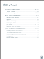
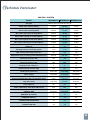
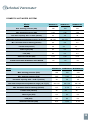
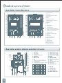
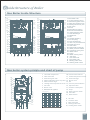
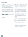
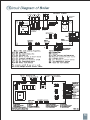
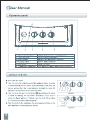
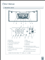
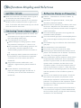
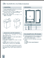
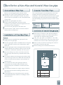
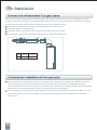
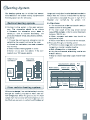
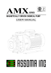
MGBWA070
Volcan Series
MGBWA090
MGBWA0100
Thank you for choosing "ENERGY" gas boiler,a wall hung boiler of the latest generation with elegant
style and advanced technology.
L1PB series is a high-efficiency boiler for heating and domestic hot water production,running on natural
gas, LPG or Artificial coal gas.
Thanks to the microprocessor control and adjustment system with advanced self-diagnosis,unit
operation is for the most part automatic.The power for heating is automatically governed by the control
system.The power for hot water is automatically and continually governed to ensure the fast delivery
and comfort under all operating conditions.
All you need to do is just set the temperature of the room and set the desired outlet temperature for the
hot water.The intelligent system will do it for you.
We hope you can enjoy the comfortable and safety experience our boiler brings you.
1. The gas pipeline of the device must be airproofing, only gas-pipe installation qualified
company can do it.
2. If there is any defect in the installation of exhausted air discharging system, it will be
possible for the exhaust regorging, incompletely burning or even CO toxicosis and
explosion. When the flue is installed, please check it carefully and keep it position.
3. The device is with system release valve and tap water release valve. If the water
pressure of system and water supply is exceeded, water will be discharged from the water
releasing port. So a pipe needs to be installed to the port, in order to protect your living
environment.
4. In the condition of freezing possible condition, if the device is not used or it can not be
repaired in time, please discharge all the system water(there should be a water
discharging valve in the lowest point of water pipe system)
5. If there is something wrong with the power supply cord, only the manufacturer, or after
service department or some qualified technician can change it to avoid the danger occur.
6. This device should be installed with smallest service port.
Product Characteristics........................................................... 03
- 06
Technical Parameter..................................................................................... 04
Inside structure of gas boiler................................................................. 05 - 06
For Users' Manipulation.............................................................07-14
Safty and Caution Instruction........................................................................ 07
water filling...................................................................................................
08
Affusion, and Drainage...................................................................................08
Circuit digram of boiler.................................................................................
10
User manual........................................................................................... 11 - 13
Malfunction display and solutions.................................................................. 14
For Installation and maintenance........................................15 - 22
Unpacking, Inspection and Acceptance......................................................
15
The connection of the water system............................................................. 17
Installation of gas pipe and coaxial flue gas pipe.........................................
18
Heating system............................................................................................... 20
Domestic hot water system..............................................................................21
Safety valve will open automatically to release
pressure to protect the the boiler from damage
Heating comfortably
Adjusting the burning efficiency which makes the
heating more comfortable. Apart from the
radiator,Household air conditioning system and
floor radiating heating system can match the
boiler.
when the water pressure reaches to 0.3 Mpa.
Temperature extremes protection.The boiler will
terminate the working program when overheated
or a temperature sensor malfunction, occurs.
Negative-pressure hermetically firing Jess
indoor oxygen consumption.
The boiler will stop working automately when the
inlet tube and outlet tube is blocked. Only when
Excellent Domestic hot water
malfunction is solved could the boiler be
Supply
restarted. Ionization flame monitoring device will
13.5Kg/m water flow can meet your daily demand.
work to shut down the operation in case the
Equipped with the latest intelligent temperature
ignition failure occurs at the beginning or during
system ,the boiler could adjust the temperature of
the process of combustion.
water even in frequent change of water pressure
Freezing protection.If the temperature of water
conditions and low pressure conditions.
in heating system drops below 8 centigrade
Optional heat water tank can supply hot water for
degree,the circulation pump will begin to work
several rooms.
and will not stop until the temperature of water
raises to 10 centigrade. When the temperature
drops to 5 centigrade, the heating system will
work until it reaches 30 centigrade. In certain
conditions, the freezing protection function may
be effected when the difference of temperature
Low noise, quick installation and easy operation.
Winter/Summer-mode Switch button, set the
heating and domestic hot water temperature at
your request.
Propotional switch can adjust the flame in order to
control the temperature of heating system water
and domestic water.
Temperature of water flow display,malfunction
code display.
between surroundings and that of pipeline is
overlarge.
HEATING SYSTEM
Model
Gas type
MGBWA070 MGBWA090 MGBWA0100
Natural gas, LPG, Artificial coal gas
Rated input capacity (Btu/h)
70.000
90.000
100,00
Rated output capacity (Btu/h)
63.000
81.000
93.300
Min. input capacity for heating (Btu/h)
36.000
38.000
38.000
Min. output capacity for heating (Btu/h)
32.000
34.200
35.800
Min. input capacity for hot water (Btu/h)
33.000
33.500
33.500
Min. output capacity for hot water (Btu/h)
27.600
27.600
27.600
AFUE (%)
90
90
93,3
Working pressure of heating system
7~43
7~43
7~43
Max. heating water temperature (Fº)
194
194
194
Adjustment range of heating water temperature (Fº)
86~176
86~176
86~176
Rated electric power (W)
125
125
125
Electrical protection (IP)
X4D
X4D
X4D
Expansion tank volume (L)
6
6
8
Expansion tank prelead (PSI)
14,5
14,5
14,5
Heating area (square Ft2)
500~1650
650~2200
850~2700
Power supply
110V/60Hz
110V/60Hz
110V/60Hz
Reference Natural Gas (12T) consumption (gom)
4~8.5
5.4~11.4
6.3~13.3
Lpg (20Y) (Lb/h)
1.65~3.45
2.2~4.6
2.55~5.4
Net weight (Lb)
80
83
88
TOTAL LENGTH OF THE LOOP CIRCUIT FT
230
230
230
PHISICAL SIZE
29X18X10
29X18X10
29X18X13
BURNERS (# ORIFICE)
9
12
14
PUMP MAX HEAT FT
16
16
19
CONNECTION PIPE BOILER
3/4
3/4
3/4
CONNECTION GAS
3/4
3/4
3/4
DOMESTIC HOT WATER SYSTEM
Model
MGBWA070
MGBWA090
MGBWA0100
Max. working pressure (PSI)
100
100
100
Min. working pressure (PSI)
7,25
7,25
7,25
Hot water capacity with ∆ t=45 F (Lb/min)
23
30
35
Hot water temperature adjustment range ( ±3 Fº) (Fº)
86~140
86~140
86~140
Min. hot water flow for starting (Lb/min)
5,5
5,5
5,5
Limited flow (Lb/min)
22
Natural gas (PSI)
0,3
0,3
0,3
LPG (PSI)
0,4
0,4
0,4
Artificial Coal Gas (PSI)
0,15
0,15
0,15
CONNECTION PIPE DOMESTIC HOT WATER
1/2
1/2
1/2
Model
22
22
MGBWA070 MGBWA090 MGBWA0100
Max. working pressure (PSI)
100
100
100
Min. working pressure (PSI)
7,25
7,25
7,25
Hot water capacity with ∆ t=45 F (Lb/min)
23
30
35
Hot water temperature adjustment range ( ±3 Fº) (Fº)
86~140
86~140
86~140
Min. hot water flow for starting (Lb/min)
5,5
5 1/2
5 1/2
Limited flow (Lb/min)
22
22
22
Natural gas (PSI)
0,3
0,3
0,3
LPG (PSI)
0,4
0,4
0,4
Artificial Coal Gas (PSI)
0,15
0,15
0,15
1. Cold water inlet
2. Gas valve
3. Hot water temperature sensor
4. Water button
5. Burner
6. Electrode for ignition
7. Electrode for flame detection
8. Heat Exchanger
9. Distributor
10. Fan
11. Smoke sampling
12. Air sampling
13. Flow limited loop
14. Valve of air pressure difference
15. Heating water temperature sensor
16. Limited temperature sensor
17. Expansion tank
18. Automatic air venting valve
19. Pump
20. Safe valve
21. Automatic bypass-valve
22. Water venting valve
G . Gas inlet
U. Hot water inlet
E. Cold water inlet
R. Heating water inlet
M. Heating water outlet
Inside Structure of Boiler
Gas Boiler Inside Structure
15
15
1.Cold water inlet
14
16
14
16 2. Hot water temperature sensor
13
17
13
17 4. Heating water temperature sensor
12
3. Automatic bypass-valve
12
18
11
10
10
9
9
8
18
11
8
19
7
20
6
21
5
22
4
23
3
24
2
25
1
M
U
G
E
19
7
20
6
21
5
22
4
23
3
24
2
25
1
R
M
U
G
E
R
5. electromagnetism three way valve
6. Gas valve
7. Burner
8. Electrode for ignition
9. Electrode for flame detection
10. Limited temperature sensor
11. Heat Exchanger
12. Distributor
13. Fan
14. Smoke sampling
15. Air sampling
16. Flow limited loop
17. Valve of air pressure difference
18. Expansion tank
19. Safe valve
20. Plate heat exchanger
21. Water pressure switch
22. Automatic air venting valve
23. Water button
24. Pump
25. Water venting valve
G . Gas inlet
U. Hot water inlet
E. Cold water inlet
R. Heating water inlet
M. Heating water outlet
Gas boiler system priciple and chart of pump
14
15
13
16
1、Hot water temperature
10、Electrode for flame detection
2、Cold water inlet
11、Limited temperature sensor
3、Automatic bypass-valve
12、Heat exchanger
4、Electromagnetism three way valve 13、Burner room
12
11
5、Plate heat exchanger
10
14、Fan
6、Heating water temperature sensor 15、Valve of air pressure difference
7、Gas valve
16、Expansion tank
9
8、Burner room
17、Automatic air venting valve
8
9、Electrode for ignition
18、Pump
7
17
19、Water pressure switch
Total Head(mH20)
7
20、Safe valve
6
21、Water button
6
18
5
4
19
3
2
5
G、Gas inlet
4
U、Hot water inlet
20
3
E、Cold water inlet
21
1
R、Heating water inlet
2
1
M、Heating water outlet
0 100 200 300 400 500 600 700 800 900 10001100 120013001400
Discharge (Kg/h)
M
U G E
R
06
I Water stored in the boiler cannot be used for
drinking or cooking, Just for daily use.
Gas type must be in conformity to type on the tag.
Please use the AC 110V/60Hz with supplied
plug.To keep safety, the boiler should have earth
connection.
Have the boiler serviced by a qualified authorized
service technician.
Please keep ventilation at times when the boiler
works.
Switch off the power and gas valve when the
boiler in malfunction, check the manual
instructions or inform the professional engineer for
repairing.
Check the water pressure meter frequently when
the pressure is too low.the boiler may stop
working and show malfunction code on
screen.Refill water and keep the pressure
between 0.1— 0.12Mpa(1— 2 bar).
To avoid freezing in cold weather, keep switch on
and gas supply going.
Turn off the electric power and cut off gas supply
when you don't use for a long time.Drain water out
of the boiler completely to avoid damage of
freezing.
The boiler should be connected with the heating
system including a gas pipeline and an outlet.
Boiler and burnet must be installed and serviced
only by qualified heating installer/service
technician. Failure to comply with the manual
could result in severe personal injury or property
damage.
The safety equipment and the automatic
regulating devices of the boiler are forbidden to be
changed on your own.
Do not install the boiler outside the house.
Switch off the power and gas supply when
cleaning the boiler.
Keep the boiler away from combustible materials,
esp. plastic materials.
Do not block the vent outlet and inlet by using
cotton or paper.
If there is gas smell or combustion smell,please
do not turn on the electronic devices,such as
power switch,telephone.Follow the instructions
below:
• open the window
• Switch off the gas supply
• Notify the technician.
Do not wet the electronic outlet and boiler. Children
and disabled people should not be allowed to
use the boiler
Keep the packing material of boiler from
children,which could be dangerous for children. Do
not pull, cut or curve the power cord.
Before affusion, turn on the automatic air vent
valve on the circulation pump and the air-vent
valve at the end of the heating system.
Fill softened water into the preset position for
affusion on the pipe of heating system.Observe
the pressure meter on the operation panel,stop
filling in water when the pressure
reaches
between 0.1-.12Mpa(1—1.12 bar)
Turn on the boiler (do not turn on the gas
valve),then the pump start working.when the
pressure drops to 1 bar, turn off the boiler.
Keep on filling softened water in until the meter
hands points to 0.1-0.12(1-1.2 bar). Restart the
boiler(do not open the gas valve),the pump will
start running.when the pressure drops again,
The boiler is equipped with a manual valve for
affusion and refilling water.Add water when the
water pressure is below 0.1Mpa(1 bar) during the
operation.
Switch off the power supply of the boiler.
Check to make sure there is no water leakage
from the heating system.
Turn the Affusion/refilling water valve in an
anticlockwise direction.
Observe the water pressure metre, till
water
pressure reaches 0.1-0.12Mpa(1—1.2 bar),turn
the affusion/refilling in a clockwise direcition,and
close the valve.
Restart the boiler.
Repeat the above steps until the pressure keeps
steadily at 0.1—0.12 Mpa(1—1.2 bar).
Turn off the air vent valve on the end of the
heating system.
Caution:As the air cannot be exhaused from the
Check the heating system pressure regularly.The
boiler pressure metre hand should be pointed at
the 1-1.2 bar. If the pressure is less than 1 bar(cold
boiler completely at first affusion.the remaining air
boiler),refilling the water by affusion valve on the
may go with steam into the water pressure detection
bottom of the boiler.
system,which may result in the lace-water-protection
system running-Refill the water until the pressure
reaches to 0.1 -0.12Mpa(1 -1.2 bar).Turn the "reset "
button,restart until the system operate steadily.
Caution
Turn off the refilling valve after the Refilling
finished,If the pressure of the heating system goes
up to 3 bar,the safety valve will be opened.Please
contact the technician.
You should keep all the parts of the boiler running
Please follow the below instruction
and the power supply on Sumer/winter
Check
button.When the water temperature is below 8
air-tightness when the gas valve is closed,then
centigrade,the burner and pump will start until the
open it, here should no gas through on the timer
temperature rises to 30 centigrade.To avoid the
display within 10 minutes
boiler keep running around the clock, or laying
Check if the gas type is in accordance with the
idle,please exhaust the air or add anti-freezing.
required ones.
Exhaust the water in the pipeline of heating
Check the connecting,L-N polarity and grounding
system.Refilling water disposed,which can reduce
when connected to the 110V/60Hz power supply.
the water hardness and avoid the sediment
Ignite the gas and check the ignition.
incrustration.
Check the dates of Max. Gas flow,medium Gas
the
air-tightness.First
check
the
flow and Min. Gas flow and relative air pressure
to see if it's accordance with listed dates.
Check the intervening progress and intervening
Use web and neutral soap to clean the boiler
shell. Never use abrasive detergent and
putty-powder.
time of safety equipment when there is no gas
supply.
Check the switches in and outside or control
display.
Check if there is any jam in the air inlet and outlet.
Seal
the
adjustment
equipment
of
gas
valve(when the adjustment is finished).
Check the water flow of domestic hot water.
Check the airproof of all water pipe.
Check the ventilation of the installation place to
make sure it can satify the requirement.
Caution:
You can only use the boiler when the check is
accomplished, f any of the item above cannot be
matched,please call the technician.
1. Winter button
2. Summar button
3. DHW temperature up/down button
4. CH temperature up/down button
5. Reset button
6. Power on/off
7. Cold indication
8. Temperature display and malfunction code display
9. Over-heat problem display
10. Summar
11. Winter
12. Heating mode
13. Normal flame indication
14. DHW mode
15. Antifreezing
16. System water pressure indicator
17. Fan motor/fan pressure on/off malfunction
18. Ignition failure
19. Temperature sensor malfunction
20. Short of system water pressure
When turn the knob 5, the boiler doesn't ignite in
CdUtion: Maintenance should be taken by
10 seconds, the red indicator 3 lights.
technician.
Check the gas valve is opened or not, press the
Gas smell. The gas has leaked, so the pipe
RESET knob to restart the boiler to ignite once
should be checked if sealed.
more, if the boiler still doesn't start up, turn off the
When the fan is operationg, the flame can't cover
boiler and ask for technician.
the burner. Maybe the fan has started, but the
point of the air pressure sensor hasn't changed. It
need examination.
The inlet-exhaust gas pipe is too long that has
When the input/output power is normal, the
exceed the size permision;
temperature is too high the boiler will show
The inlet-exhaust gas pipe is blocked.(Maybe the
the overheating malfunction.
part of the inlet pipe and the part of the exhaust
The causations are as follow:
pipe.)
• Water lackage in heating system. Check
The isolation ring is not fitted to the inlet-exhaust
the pressure is during the 1-1.2bar or not.
gas pipe;
• The circulation in the heating system is not
The sealed box is not sealed well.
so smoothly, check the pipeline in the
The power of the fan is lower than 196V.
sealed heating system and air vent works or
The burning is abnormal that the flame is red or
not.
yellow. The causation are as follows. The burner
• To restart the boiler, please turn the knob 4
is too dirty. The wrong tie-in terminal..
to the RESET If this malfunction happened
Over temperature and the pressure meter shows
continully, turn off the boiler and ask for
frequently boiler malfunction.This is caused by
technician.
the lack of system water, the abnormal heating
Air pressure sensor malfunction—red
system water circulation and the block in the
indicator 3 lights and the yellow indicator 2
circulation system. Check the pressure meter to
lights
ensure the pressure is under 1-1.2bar. Be sure
In this situation, check the air inlet
that the valve of the heating system are all closed
pipe, the exhaust gas pipe and the fan. If
and the operation of the circulation system is
necessary, turn off the boiler and ask for
normal.
technician.
The air is not emptied in the system. Check the
safe valve to be opened, the pressure of the
boiler and the expansion vessel at the ranged
pressure. The pressure of the expansion vessel
should be at LObar, the pressure of the boiler
should be at 1-1.2bar.
The circulation pump maybe blocked because it
is not used for a long time. Please disassemble
the front of the pump, running the motor base by
screwdrive. Do this carefully.
MGBWA100N11LA
The circulation pump head and flow should
match the boiler system
The whole system should be clean,with no
sediment, rust, leakage, and drip-drop.
While affusing and refilling water. a waterpurification must be equipped.
Don't install the boiler to the place close to any
combustible material.
The wall on which the boiler is installed must be
able to support a hang weight of 45KG,and if it's
made of combustive materials,it should be
covered with anti-combustive at least 3 mm thick.
Never install the boiler in places where
combustion and volatile drugs are stored or used.
Don't install the boiler under any dangerous shelf
staff that maybe drop.
Don't install the boiler above other gas
applications.
The outlet of the flue gas pipe shall be installed at
places with good ventilation.
For natural gas and LPG users, D15 gas pipe can
be used. However we advise you use D20
pipe,the reducer pipe connecting with the gas
meter should less than D15.
Keep a stable voltage of 110V,Use constant
voltage regulator.
It is forbidden to use hemp thread for connecting
pipe. Use coarse plastic tapes. If hemp thread has
to be used in certain conditions,please
completely clean the pipes with compressed air
at 8 bar pressure.
Radiator of 150 square meter might be installed
in your room—you have to install the Y-shape
filter in the return water of heating system.
The outlet of safety valve must be connected to
floor drainage, there shall not be any valve on
connection pipe.
For system with cast iron radiators,please
completely clean the pipes and radiators with
high-pressure water or compressed air at 8 bar
pressure.In areas where water quality is
poor,please clean the system several times. Use
softened water for affusion of system.
For Installation
Fix the hanging board for installation
Adjust the hanging board with a gradienter
Add washer if necessary.
Mark the fixing points.
Take off the hanging board and drill holes on the wall
Fix the hanging board on the wall with screws
Adjust it level with a gradienter
MGBWA100N11LA
Attention: The min. space should be allowed for the maintenance purpose, as shown on the right picture.
Min45mm
148
55
A
Model
55
A
MGBWA100N11LA
50
B
Model
A
MGBWA100N11LA
198
A
270
B
230
The Connection of water system
①
②
③
④
⑤
⑥
Affusion/Refilling
Safe valve discharge port
⑦
G
MODEL
①
②
③
④
⑤
⑥
⑦
G:Gas U:Domestic hot water
17
U
E
R
M
MGBWA100N11LA
71
70
88
95
70
66
173
E:Domestic cold water R:Heating backwater
M: Heating hot water
Before connecting gas pipes, please check:
Whether the type of gas supplied matches that
specified on the name plate of boiler. Any other
types of gas not specified on the name plate shall
not be used.
Whether the gas pipes are clean.
Please install a gas filter if there are solid
particles in gas. Please check the tightness of all
connections after installation.
Do not use the gas pipe as the earth wire.
There must be a pipe, which connects outlet of
safety valve to the ground.
Please use the supplied flue gas pipe.Do not
modify the flue gas pipe.
The flue gas pipe shall be installed with a 2-degree
slope outward to ensure the condensation water
flows out.
The flue gas pipe must be wrapped with refractory
material thicker than 200mm when it goes through
a wall with combustive materials. Do not lay the
pipe into ceiling.If you have to do this,cover the
flue gas pipe with refractory material thicker than
20mm.
The space between the flue gas pipe and the wall
it goes through shall not be filled with hard articles
such as cement.which makes it inconvenient for
maintenance.
The outlet and inlet of flue gas pipe shall be
extended to the outside wall,and shall not be
blocked.Keep the ventilation of exhaust and airentering.
The distance between the upper edge of the flue
gas pipe and the above building shall be more
than 45mm.
If extended pipe are used,all the joints must be
well sealed and there shall be no leakage of flue
gas into house.
The coaxial flue gas may be adjusted to the most
suitable direction according the requirement of
installation. The chart below show the linear lenghts
of flue gas pipe with and without flow-limiting ring.
The flow limiting ring shall be removed with a screw
driver.
Drill a hole of 105mm on the wall according to
the installation module.The whole shall have a
downward of 2 degree toward outside.
If the flue gas pipe is installed in the side
wall,draw a horizontal line from the centre of the
module to the centre of the outlet flue gas pipe.
Draw a circle of 105mm centering the centre of
the outlet of the flue gas pipe.
Drill according to the circle drawn above.
MGBWA100N11LA
The whole length of flue gas pipe is decided by the the distance between the boiler mouted place and the
position outlet of flue gas pipe. The distance also decide whether the flow limited loop shall be removed and
whether the extended pipes shall be used.Please refer to the diagram below
Extend the standard gas flue pipe outward through the hole in the wall
Install the flanges of flue gas pipe
Install the elbow union at the outlet of the flue gas pipe and inlet of boiler
Connect the extended flue gas pipes with the elbow and the standard pipe
Pay attention to the air tightness of the flue gas pipes.While installing the elbow union,please make sure
that its inner pipe is correctly jointed with flue gas exhaust pipe on the boiler and all pipes are firmly
connected with the boiler.There must be no less than 30mm between the elbow and the standard pipe and
betweent the two extended pipes,to assure the airtightness of the wholepipe.
The connection of flue gas pipe includes standard connection and extended connection.In either way only
one standard pipe is used.The numbers of elbows and extended pipes are not allowed to exceed the
length of line.
Hot water system is to meet the demand of domestic hot water,say the bath.It's composed of
boiler,pipe,sanitary equipment(The following systems are for reference)
Generally,there are two systems based on the different equipments and theory:Without water tank simple
system and with water tank system.
without water tank system
The system is composed of boiler,sanitary hot water equipment and pipe.The boiler is connected with
sanitary equipment by pipe.As the picture 3.4
When turning on the hot water tap,the water goes through the boiler,the sanitary hot water function
works,and heats the water that goes through the boiler.Now you have to drain the cold water out,then it
comes out the hot water.
The system is suit for the equipment that the hot water pipe is not too long,(the boiler is close to the
equipment where hot water is used).The system is easy to install,less investment,and can supply water for
2-3 places.
The water tank is equipped with a temperature sensor,which can watch the temperature inside of the
tank.When the temperature is below the set temperature,the sensor send the information to the pump
which begins to work,then the water in the tube flows,so the heating function of the boiler starts,When the
temperature in the tank reaches the set temperature,the termperature sensor give the signal to the
pump,which will stop working.The stable water temperature can be kept and ensure the realtime supply of
hot water.
The system has hot water circulation pump in addion,esp.for the system with a long pipe.lt can supply hot
water immediately .In addition,we have a water tank,which can supply 3-5 places with stable temperature
hot water much more comfortable.
Attention: The system must equip the pump.
Klimaire Products Inc.
7909 NW 54th Street
Mimai, FL. 33166
Ph. 305 5938358
Fax. 305 5938212
www.Klimaire.com